Front Chassis Components for a “Green” City Vehicle
Info: 19290 words (77 pages) Dissertation
Published: 13th Dec 2019
Tagged: AutomotiveEnergy
Design, development and manufacture of front chassis components for a “green” city vehicle.
ABSTRACT
There is currently ample research into the effects of vehicle emissions on the health of the planet. There are also widespread designs in a mass production environment aimed at reducing vehicle emissions and increasing fuel efficiency. However, there is less research into the emissions produced at the end of a vehicles life and the POLIS project aims to address this gap in global understanding. The purpose of this report will be to document and reflect on the design, development and manufacture of front suspension components for the POLIS project. This will include any challenges faced during the project and any notable findings.
ACKNOWLEDGEMENTS
I would like to sincerely thank my project supervisor, Dr. George Haritos, for his constant support, criticism, guidance and time throughout the project. Additionally, Mr. Behrad Vehedi for his role as second assessor and offering support in Dr. Haritos’ absence.
I would also like to thank all other members of staff at the University of Hertfordshire that helped with this project, including but not limited to Dr Howard Ash for assistance with Lotus Suspension Software, Mrs Susan Murray for guidance with CNC processes and the technical and fabrication staff (Mr. Gkizelis, Mr. Rajanayaka, Mr. Maynard and Mr. Jani)
Additionally, I wish to thank my POLIS team mates for their assistance and shared enthusiasm for this project and my other fellow students for their help and encouragement.
I also would like to offer special thanks to my family and others for their endless support.
TABLE OF CONTENTS
3.2.1 Bosch Automotive Handbook
3.2.3 Specific City Vehicle Literature
4 PRODUCT DESIGN SPECIFICATION
4.2.1 Wishbone Technical Specification
4.2.2 Prototype Wishbone Technical Specification
4.2.3 Upright Technical Specification
4.2.4 Prototype Upright Technical Specification
4.3 Quality Function Deployment
5 CONCEPT CREATION AND SELECTION
5.1.4 Rack and Pinion Steering Systems
5.1.5 Pitman Arm Steering Systems
6.1 DETAILED MODELLING AND ASSEMBLY
7.1.1 CATIA .v5 Finite Element Analysis
7.1.2 ANSYS Finite Element Analysis
7.1.3 Lotus Suspension Analysis
7.2.1 CATIA .v5 Finite Element Analysis
7.3 FAILURE MODE AND EFFECTS ANALYSIS
8.1 IMPROVEMENT ON PREVIOUS YEARS
LIST OF FIGURES
Figure 1 3D Model of 2015 POLIS Vehicle
Figure 2 Fiat Group 2013 Roadmap of Propulsion Systems (8)
Figure 3 A Comparison of some Personal Mobility Products for Urban Use (11)
Figure 4 PDS Generation Matrix BS 7373, 2005
Figure 6 Sketch for MacPherson Strut Concept
Figure 7 Sketch for Double Wishbone Concept (Lower)
Figure 8 Sketch for Double Wishbone Concept (Upper)
Figure 9 Sketch for Trailing Arm Concept
Figure 10 Sketch for Rack and Pinion Concept
Figure 11 Sketch for Worm and Sector Concept
Figure 12 Pitman Arm Steering System (18)
Figure 13 Production Intent Upright Catia Solid Model
Figure 14 Production Intent Wishbone Catia Solid Model
Figure 15 Production Intent Upright Iterations
Figure 16 Prototype Upright Catia Solid Model
Figure 17 Prototype Wishbones Catia Solid Models
Figure 18 Finished Prototype Upright (Right) vs. Old Upright (Left)
Figure 20 Incomplete Machining Visualisation from Front
Figure 21 Incomplete Machining Visualisation from Side
Figure 22 Upright Lower Joint Prototype (Right) vs. Production Intent (Left)
Figure 23 Catia von Mises Stresses under Braking
Figure 24 Catia von Mises Stresses under braking and cornering
Figure 25 ANSYS workbench von Mises Stresses under Braking
Figure 26 ANSYS workbench von Mises Stresses under Braking and Cornering
Figure 27 Catia and ANSYS comparison chart: von Mises Stress vs. Software package and Model
Figure 28 Lotus Shark Suspension Steering Analysis
Figure 29 Lotus Shark Suspension Roll Analysis
Figure 30 Catia von Mises Stresses of Prototype Upright
Figure 31 Catia von Mises Stresses of Prototype Upper Wishbone
Figure 32 Catia von Mises Stresses of Prototype Lower Wishbone
Figure 33 Catia von Mises Stresses of Prototype Lower Wishbone (without psgr or battery)
Figure A – 1 Sketch of Ball-joint Fixing Concepts 1
Figure A – 2 Sketch of Ball-joint Fixing Concepts 2
Figure A – 3 Sketch of Strut Mounting Bracket Concept
Figure A – 4 Sketch of Recirculating Ball Steering Box Concept
Figure B – 1 Production Intent Upright Technical Drawing
Figure B – 2 Production Intent Wishbone Technical Drawing
Figure B – 3 Prototype Upper Wishbone Technical Drawing
Figure B – 4 Prototype Lower Wishbone Technical Drawing
Figure B – 5 Prototype Upright Technical Drawing
Figure B – 6 Assembly Technical Drawing Sheet 1
Figure B – 7 Assembly Technical Drawing Sheet 2
Figure C – 1 3D Model of Lower Ball-Joint in Inclined State
Figure C – 2 3D Model of Suspension Strut
Figure C – 3 3D Model of Modified Brackets
Figure C – 4 Strut Collar Technical Drawing
Figure D – 1 CAE Machined Upright
Figure D – 2 Upright Machining Tool Path Simulation
Figure D – 3 2015 Old POLIS Front Suspension
Figure D – 4 Finished Prototype Uprights
Figure E – 1 Load Calculations for Production Intent FEA Load Cases
Figure E – 2 Raw Results from FEA
Figure E – 3 Catia Displacement of Upright under Braking
Figure E – 4 Catia Displacement of Upright under Cornering and Braking
Figure E – 5 Catia Displacement of Old Upright under Cornering and Braking
Figure E – 6 Catia von Mises Stress of Old Upright under Cornering and Braking
Figure E – 7 Catia von Mises Stress of Production Intent Wishbone
Figure F – 1 Lotus Shark Suspension Analysis 3D Parameters
Figure F – 2 Lotus Shark Suspension Analysis Suspension Co-ordinates
Figure F – 3 Lotus Shark Suspension Analysis Top View Static and Full Lock
Figure F – 4 Lotus Shark Suspension Analysis Static Side View
Figure G – 1 FMEA Severity Criteria and Rating Definition
Figure G – 2 FMEA Likelihood of Occurrence Criteria and Rating Definition
Figure G – 3 FMEA Likelihood of Detection Criteria and Rating Definition
LIST OF TABLES
Table 1 Material Comparison Matrix
Table 2 Suspension Layout Selection Matrix
Table 3 Human Responses to Vibration (25)
Table 4 Wishbone Natural Frequency Modes
Table 7 Production Intent Upright Synthetic Cost Analysis
Table 8 Production Intent Wishbone Synthetic Cost Analysis
Table 9 Prototype Upright Synthetic Cost Analysis
GLOSSARY
POLIS – Greek word for city, the POLIS vehicle is a three-wheeled city vehicle developed to have the smallest possible carbon footprint “cradle to grave”.
2015 POLIS Vehicle – Refers to the vehicle prior to this project.
2016 POLIS Vehicle – Refers to the vehicle at the end of this project.
CAD – Computer Aided Design.
CAE – Computer Aided Engineering.
PDS – Product Design Specification.
FEA – Finite Element Analysis.
FMEA – Failure Mode and Effects Analysis.
RPN – Risk Priority Number, as used in FMEA is a numerical value given based on risk level.
CNC – Computer Numerical Control.
ELV – End of Life Vehicle.
OEM– Original Equipment Manufacturer (used interchangeably to mean multinational automotive manufacturer).
EU – European Union.
USA – United States of America.
OTR – “On the road” when referring to cost, OTR price is the total price for the customer to drive away the vehicle.
DFM – Design for Manufacture.
DFA – Design for Assembly.
DFMA – Design for Manufacture/Assembly.
Mule Car – Test bed vehicle with prototype parts fitted.
A Surface – Vehicle surfaces of highest quality, surfaces that will be visible to the consumer.
Poka-yoke – Japanese term for mistake-proofing, mechanism of lean manufacturing, used when assembling components on a production line to prevent human mistakes.
Cpk – Measure of a production machine’s variation and location of the variation within the part tolerance range.
JIT – Just in Time manufacturing system aimed at reducing flow times between supplier and production line and also within the plant.
1 INTRODUCTION
Climate change is an ever-worsening problem in the modern era and the situation is almost unanimously agreed upon by leading scientists. Road transport contributes over 10% of total global greenhouse emissions (1) and is understandably under a large amount of focus in terms of reducing humanities negative impact on the environment. The problem is worsening so rapidly that by 2050 transport could contribute between 30% and 50% to total global emissions (1). Only 80% or even as low as 50% (2) of an individual vehicle’s emissions occur during its daily use, meaning a large proportion of emissions occur during the production and disposal phases.
Urban and metropolitan living has seen unprecedented growth in recent years with an expectation that around 70% of the world population will be urban by 2050 (3).
Due to this increased urbanisation and new cities rarely being formed, many of the current cities will likely become megacities, with populations of over ten million inhabitants. This development is more prominent in less developed countries, in 1970 only one megacity could be found in the developing world, by 2025 that number could be as high as twenty-two (4). Current infrastructure in cities is close to breaking point in most cases and this population increase will mean our current solutions will quickly become unsustainable.
Therefore, development of highly efficient and practical city vehicles is required to overcome the problem facing city transport. Named after the Greek word for city, the POLIS vehicle shown in Figure 1, is designed solely for this purpose. It is a compact, efficient and sustainable vehicle, designed to fit into our rapidly expanding cities, while minimising the negative impact on the environment.
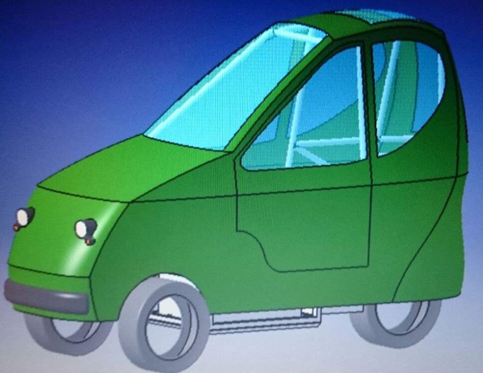
Figure 1 3D Model of 2015 POLIS Vehicle
This report will comprehensively document and consolidate all the work undertaken by the author during the creation of the front suspension system for the POLIS vehicle, from initial concept creation and brainstorming techniques, through to prototype manufacture. The report will also summarise the latest research in the fields of biodegradable vehicles and city vehicle suspension, highlighting any findings as to the future of urbanised transport.
2 PROJECT AIMS AND OBJECTIVES
The project aims and objectives dictate the direction of the project and are reassessed against the outcomes of the project to quantify the success of the project.
2.1 PROJECT AIM
The primary aim of the project is to design, develop and manufacture the front chassis components for the POLIS vehicle, as stated in the formal title. In addition to this a 1:1 scale prototype of the vehicle’s front suspension system will be required for the physical display vehicle.
2.2 PROJECT OBJECTIVES
In order to achieve the above aims, the project will follow Stuart Pugh’s Total Design methodology and practice (5). The project background will be researched allowing a product design specification (PDS) to be created and from this multiple concept designs will be developed. Concepts will undergo selection processes to establish the best concept for further development.
After finalising the chosen design, the components will be modelled in detail and analysed through various finite element techniques. Designs will be evaluated and the author will indicate key areas for further study. Targets for the design of the front chassis components will focus around reducing the carbon footprint of the parts at the end of the vehicle life, (LCA3).
Throughout the project, theoretical production intent designs and prototype designs will be treated independently. The objective of this is to allow the author full design freedom with mass production techniques, to address the project aims above, and yet still create representative prototypes with the resources available and manufacturing limitations.
3 LITERATURE REVIEW
3.1 STANDARDS
The following international standards were read to gain an understanding of the various restrictions the POLIS vehicle would have to abide by as well as legislative solutions to the increasing problem of carbon emissions when disposing of a vehicle. Corporate environmental reports were also studied to see current OEM solutions to international standards.
3.1.1 ISO14001 and ISO14040
The ISO14000 family of international standards outline a company’s obligations to environmental management and systems for ensuring compliance with them. For this project, two standards were referenced due to their relevance to automotive applications. ISO14040 specifies the requirements that companies need to meet as well as defining the goal of performing LCA. ISO14001 is more guidance based and shows the company the route in which to take to achieve goals laid out in ISO14040. All large car companies will have certification with both these standards and therefore it is beneficial to the project to understand the problems faced with adhering to LCA standards and therefore ensure the POLIS vehicle would be correctly situated in the global market. It also shows what considerations are already made by companies which can be built upon to improve their efficiency.
3.1.2 ELV Directive
The End of Life Vehicle directive is an official instruction from the European parliament and council of the EU, to all member states, to bring together all legislation concerning end of life vehicles into one comprehensive and clear “community-wide framework”. The ELV directive has been in place since 2000 and provides the author with an understanding of the legislation enforced by the EU, which vehicle manufacturers must abide by. It encourages multiple movements on an international scale such as the development of markets for recycled materials, the design of recyclable vehicles from the first instance and sharing international data and statistics regarding recyclability.
3.1.3 Fiat Group Reports
The Fiat Group’s Environmental report 2006 (6) contains useful schematics and information about the group’s impact on the environment, it highlights what contributes the most to CO2 emissions in such a large fleet of vehicles. It also outlines steps they are taking to combat their negative environmental effect in all three phases of LCA, production, vehicle use and disposal. The 2013 Sustainability report (7) provides a large level of detail regarding the Group’s strategy to minimise their overall emissions. This includes information concerning new technology implemented across their full fleet including their premium and luxury Ferrari and Maserati Brands, their adherence to ISO14001 and ISO14040 mentioned above, alternative mobility solutions as well as a breakdown of all propulsion systems used as shown in Figure 2. This provides an extremely useful overview of the current technological landscape in automotive companies and the many systems they’re implementing.
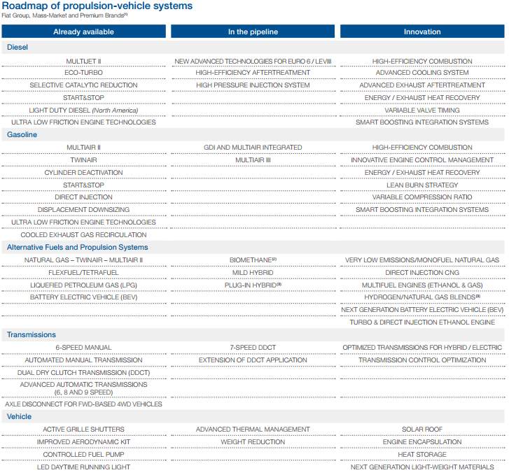
Figure 2 Fiat Group 2013 Roadmap of Propulsion Systems (8)
3.2 SYSTEM LAYOUTS
There is a large amount of high quality material surrounding vehicle suspension, a small pool of this was used to expand on the authors understanding of fundamental suspension design. The following resources were used for in-depth understanding of the required components and to gain various insights on practical solutions to suspension design for city vehicles specifically.
3.2.1 Bosch Automotive Handbook
The Bosch Automotive handbook was used extensively by the author during all stages of the design and development processes. The Bosch group publishes the reference book, one of the world’s largest component suppliers in the automotive sector. This position in the industry relates to a diverse product range and knowledge base, thus the book contains a wealth of very broad and detailed information regarding the chassis system and the vehicle overall. During concept selection, the handbook contains detailed comparison graphs of which apply fully to this project. Being of recent publication, the book’s stance on environmental issues and the effects of vehicle disposal offer key insights into the aforementioned standards in addition to the exclusive material surrounding end of vehicle life.
3.2.2 Halderman Series
The Halderman series of workshop reference guides are presented in a textbook style, aimed at technicians, providing a detailed and simple review of each system and component in the chassis. This was used for initial visualisation of system layouts and also gaining a more complex understanding of various mechanisms. The Halderman series offered the author good reference during the DFM and DFA stages (9), contains comprehensive discussion and consideration of corrosion and failure modes, historic and modern examples of corrosion prevention techniques were designed into the POLIS components based on such recommendations. This yielded better quality designs at a higher rate than designing more iterations without consideration to corrosion, thus having to redesign many further times to ensure longevity.
3.2.3 Specific City Vehicle Literature
Books such as L. Solman’s Car Sick (10), gave ample evidence on the need for city vehicles and what challenges the current system of motor transport is facing. Although often forming anti-vehicle arguments, the book offered the author good insight into potential solutions to the problems cities are facing in terms of transportation and focusses on a world where everything is not so car or vehicle centred but where the focus is placed more on people. This could be a potential world to which the POLIS vehicle is suited. Therefore, the book highlights strong areas of focus when designing for a futuristic period beyond the author’s current comprehension that the vehicle may occupy. This allows for a certain level of future proofing to be designed into the POLIS vehicle from an early stage.
Another approach more focussed on personal vehicles in the future city is the bitCar concept covered in Reinventing the Automobile (11). The concept is where cars are stacked on the road side to save space. It also contains Figure 3, showing a comparison of some personal mobility products and therefore highlighting where within the market the POLIS vehicle can be aimed. There is also useful discussions and diagrams showing the cost impact of using USVs (ultra-small vehicles), as termed in the book, as opposed to a conventional sized car with an internal combustion engine.
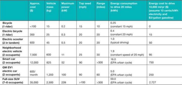
Figure 3 A Comparison of some Personal Mobility Products for Urban Use (11)
Small is beautiful (12) is a brief article showing the packaging of the Toyota IQ and the design considerations and challenges encountered when developing the suspension package for the city vehicle. The article also contains measurements of use to the author and explains how new load bearing capabilities have been introduced onto the car. The steering rack system is also reviewed and explained providing valuable industry insights into the design and mass production of successful cars similar to the POLIS vehicle.
3.3 MATERIALS
The breadth of research available on the topic of materials that could be applied to the POLIS project is vast. For this reason, it was concluded that to best serve the project aims, detailed research into material choices would only be briefly mentioned in this report. This allowed the project to remain heavily focussed on design. The resources below were reviewed by the author during material selection and provided a useful understanding of current biodegradable material options.
The comparison matrix, Table 1, shows all materials that were researched. The materials were compared using high strength steel as a datum. The importance weighting of each criterion was based on a combination of project aims as well as a short poll of current car owners, this was ranked 1-5, with 5 carrying the highest importance. Each material was then compared to the datum and set a value between -3 and +3, with +3 being the best vs. the datum.
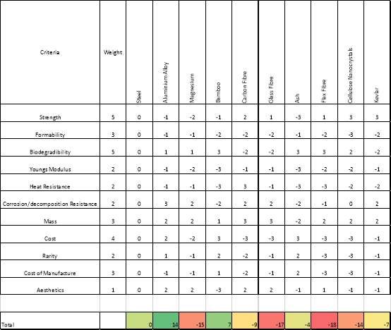
Table 1 Material Comparison Matrix
Table 1 shows the most preferable material for the chassis components of this project is Aluminium Alloy, this appears to stem from three main factors: cost vs. strength vs. mass. Despite not being a biodegradable material it is widely recyclable which can save up to 21 barrels of oil per tonne recycled (13).
Cost appears to be the main factor holding back most alternatives, it can therefore be expected that if any expensive and biodegradable materials listed above, such as flax fibre or cellulose nanocrystals, were to be become cheaper to manufacture in the future, they would replace the aluminium as the most preferable. The same can be said for the cheap, biodegradable but weak materials such as bamboo and ash, if a method was found to heavily improve their mechanical properties at little cost, they would again surpass the Aluminium Alloy as most suitable.
4 PRODUCT DESIGN SPECIFICATION
A product design specification (PDS) is necessary to ensure the project remains on track and have its success quantified and measured. At an early stage the PDS needs to be as complete as possible to ensure that the direction in which the project will focus is clearly defined.
Figure 4 below, displays a table generated from BS 7373-1, 2001 (14) to aid in the creation of the multiple PDS’s required for the project.
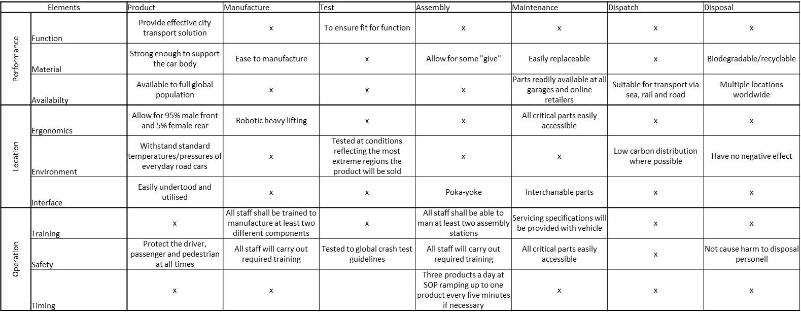
Figure 4 PDS Generation Matrix BS 7373, 2005
4.1 FULL SYSTEM PDS
The PDS for the full system incorporates Stuart Pugh’s 32 product specification elements where appropriate (5). They are as follows:
Performance
- Must be able to keep up with the pace of vehicles on a standard city road.
- Must come to a complete stop within a safe distance when required.
Environment
- Must operate as normal between the temperatures of -20°C and 50°C.
- Paint must remain intact and not bubble under high humidity.
- Paint must survive 500 hours of salt spray testing without any red rust.
Life in Service (Performance)
- All rubber components to last 90,000 miles or 8 years, whichever comes sooner, without debonding. Excluding tyres.
- Vehicle must have suitable corrosion resistance to be stored outside in a city for its lifetime.
- All structural components must remain fully operational up to 90,000 miles or 8 years.
Maintenance
- Battery must be easily accessible.
- Serviceable parts must be easily accessible and removed through the use of limited specialist tools.
- Fluid levels must be easily visible.
Target Product Cost
- The vehicle will cost no more than £5,000 OTR or equivalent local currency, at the time of sale.
Competition
- A teardown to competitor vehicles will occur for benchmarking purposes.
- All performance, mass and costing data shall be compared to the market leader at the publication date of this document.
Shipping
- Shall be shipped via rail and sea.
- The vehicle will be inspected for damage before and after shipping.
- Will have suitable ground clearance to allow for on and offload from a cargo ship (at least 200mm at the front and rear).
- The vehicle will travel up cargo ship onramp unaided and under its own power.
Packing
- The vehicle will require an adapted rig to attach solidly to a standard American two deck auto rack for transport via rail.
- Shall be suitably protected to avoid corrosion when travelling for up to 9 weeks in an environment with high sea salt concentration.
Quantity
- 12,000 vehicles will be manufactured annually.
Manufacturing facility
- Production tooling should be easily adaptable and/or derived from existing machinery to allow for sharing of facilities or production of multiple models on a single line.
Size
- Height shall not exceed 1800mm.
- Width shall not exceed 2900mm.
- Track width shall not exceed 900mm.
Weight
- Vehicle curb weight shall not exceed 450kg.
- Gross vehicle weight including 95th percentile male and 5th percentile female occupants shall not exceed 600kg.
Aesthetics
- Shall be available in a minimum of 6 base colours
- Shall come with optional extras, including but not limited to alloy wheels, two tone paint, leather interior and tinted sunroof.
- Paint will be free from bubbling on all A surfaces.
- The vehicle will have a high gloss finish.
Materials
- No UK, EU, North American or Asian banned substances will be used in any area of the vehicle.
- The use of biodegradable materials will be used in all areas, with respect to economic and safety considerations.
- The use of recyclable materials will be used in all areas where biodegradable materials are unsuitable, with respect to economic and safety considerations.
Product Life Span
- The vehicle will be marketed with an extended warranty lasting 7 years.
- The vehicle will remain roadworthy for at least 8 years from the date of sale, provided fair use and annual servicing.
Standards and Specification
- The vehicle will follow all BSI Standards for Automotive Manufacture.
- The vehicle will follow all Regulation and Competitiveness guidelines of the EU Automotive Industry.
Ergonomics
- The vehicle will comfortably accommodate the 95th percentile male in the driver seat.
- The vehicle will comfortably accommodate the 5th percentile female in the rear seat.
- Pedals will be reached without strain by the 5th percentile female and 95th percentile male.
- The steering will be manipulated without strain.
- The pedals will require minimum force to operate to the fully depressed position.
- The internal and external door latches will be accessible, without strain, for the 5th percentile female and 95th percentile male.
Customer
- The first key demographic is a modern, city dwelling, and environmentally conscious person with an interest in the technology of tomorrow.
- The second key demographic is a retired, town or city dwelling person that makes short journeys but is either unable or unwilling to make them by foot or other means.
Quality and Reliability
- Vehicle and all constituent components shall be made to ISO9001 standards.
Shelf Life
- The vehicle shall be stored for a maximum of 3 months before a secondary inspection to ensure roadworthiness and depreciation are of a suitable level.
- If storage time more than 3 months is to be expected, the vehicle must be stored in a controlled environment.
Time-scales
- The vehicle shall be in production within 2 years of the date of this document.
- Development budget shall be maintained for this period.
Testing
- Prototype testing of components on a similar “mule car” will be carried out.
- 12 vehicles will be manufactured off line using components from production tooling, these are to be crash tested. 2 of these vehicles will be used for crash testing.
- All components are to be tested against their individual standards either in-house or at the supplier. In this instance, the supplier is to provide a testing report according to the individual component standard.
- All safety critical components are to be tested in-house, regardless of supplier testing.
- The first 5 vehicles produced on the main production line are to be inspected fully. Full test routes and environmental testing shall be carried out.
- 3 Production vehicles shall be provided to EURO NCAP for independent crash testing.
- All vehicles will undergo an end of line inspection before transport to ensure they are fit for sale.
Safety
- Must comply with the UK MOT test requirements.
- Must comply with all EU, Japanese and North American roadworthiness test requirements.
- The cockpit shall not deform in a crash scenario.
- Additional measures must be taken to ensure maximum possible occupant safety during a side impact.
- Battery must be protected during a crash scenario to limit deformation and prevent puncture.
Patents, Literature and Product Data
- The vehicle or any of its constituent components shall not infringe any patent law.
Political and Social Implications
- The vehicle will be marketed to change social expectations around green city vehicles and precautions shall therefore be taken to minimise any negative backlash from the media or public.
Documentation
- The vehicle shall be shipped with a servicing and maintenance information pack.
- Workshop manuals shall be made publicly available from date of the first manufacture.
- Required tyre pressures shall be given on the inner surface of the door, charging instructions shall be provided inside the charging cap cover, jacking instructions shall be provided with the jack.
Disposal
- Disposal of all hazardous materials will be stipulated.
- Vehicle shell will be biodegradable.
- Recyclable materials will be easily removed from the vehicle for recycling.
4.2 TECHNICAL SPECIFICATIONS
More detailed technical specifications were created using engineering language and values to limit the direction of the concepts before creation.
4.2.1 Wishbone Technical Specification
The POLIS production intent wishbone:
- Shall withstand 1.2x vehicle curb weight at any given point and angle.
- Shall allow free movement of the steering knuckles in all orientations necessary.
- Shall be less the 250mm long.
- Shall have a mass of no more than 5kg.
- Shall be fully recyclable or biodegradable.
- Shall have a smooth appearance.
- Shall last 90,000 miles or 8 years, whichever comes sooner, without non-critical fracture.
- Bushes shall last 90,000 miles or 8 years, whichever comes sooner, without debonding.
- Bushing rubber shall last 90,000 miles or 8 years, whichever comes sooner, without a crack longer than 4mm.
- Shall be easily contained within the area between the lower edge of the vehicle body and the wheel with an overall track width of 900mm.
- Shall have a clearance of at least 10mm with the brake disc, calliper and tyre.
- Shall have anchorage points to allow for safe transport via road, rail and sea.
- Shall be positioned in such a way that the vehicle’s ground clearance will exceed 160mm.
- Shall be manufactured to minimise waste using JIT and lean production principles.
- Shall not have any sharp edges. Minimum radius of 2mm.
- Any holes shall undergo machine deburring or, if necessary, shall be manually deburred.
- Shall use readily available and sustainable material sources.
- In a 100kmph crash scenario, the wishbones shall deform to transfer the loads into the main body structure.
- Shall have visual and audible signs of critical failure to ensure occupant awareness.
- Shall have poka-yoke features on key faces to ensure correct assembly.
- All materials shall abide by global substance use laws.
- Suitable stock shall be made available for servicing and repairs for at least 10 years after initial vehicle production.
- The material shall provide suitable properties between -50 and 50 Degrees Celsius.
- Shall show no signs of red rust after 800 hours of salt spray testing.
- Shall be distributed by the most carbon efficient system in place at the time of production.
4.2.2 Prototype Wishbone Technical Specification
The prototype wishbones:
- Shall provide similar geometry to that of theoretical wishbones.
- Shall be able to support vehicle body under demonstration conditions.
- Shall be manufactured in such a way to allow quick and inexpensive changes.
- Shall be designed to be fabricated within 2 hours.
4.2.3 Upright Technical Specification
Similar to the wishbone technical spec in section 4.2, the upright technical spec is adapted to the differences between the components.
- Shall withstand 1.2x vehicle curb weight at any given point and angle.
- Shall allow the wheels to rotate freely 360 degrees.
- Shall fit within 15 inch diameter wheel with at least 50mm clearance to the inner surface.
- Shall have a mass of no more than 2kg.
- Shall be fully recyclable or biodegradable.
- Shall have a smooth appearance.
- Shall last 90,000 miles or 8 years, whichever comes sooner, without non-critical fracture.
- Bushes shall last 90,000 miles or 8 years, whichever comes sooner, without debonding.
- Bushing rubber shall last 90,000 miles or 8 years, whichever comes sooner, without a crack longer than 4mm.
- Shall be supported top and bottom by the wishbones and not deviate more that 5mm from this geometry.
- Shall not deform under nominal point load while being exposed to temperatures of 400 Degrees Celsius or the maximum heat dissipation from the brake system.
- Shall withstand shock loads from 100mm curbing at 30kmph ten times without critical failure.
- Shall be positioned in such a way that the vehicle’s ground clearance will exceed 160mm.
- Shall be manufactured to minimise waste using JIT and lean production principles.
- Shall not have any sharp edges. Minimum radius of 2mm.
- Any holes shall undergo machine deburring or, if necessary, shall be manually deburred.
- Shall use readily available and sustainable material sources.
- In a 100kmph crash scenario, the steering knuckle will remain connected to the wheel and ensure it is not separated from the main vehicle body.
- Shall have visual and audible signs of critical failure to ensure occupant awareness.
- Shall take an instantaneous moment from brake calliper in operable range without deformation.
- All materials shall abide by global substance use laws.
- Suitable stock shall be made available for servicing and repairs for at least 10 years after initial vehicle production.
- The material shall provide suitable properties between -50 and 50 Degrees Celsius.
- Shall show no signs of red rust after 800 hours of salt spray testing.
- Shall be distributed by the most carbon efficient system in place at the time of production.
- Shall locate connectors for ABS sensors, hydraulic braking lines and any other auxiliary connectors to ensure there is no interaction with the wheel.
- Shall be designed for casting.
4.2.4 Prototype Upright Technical Specification
- Shall represent the theoretical steering knuckle as best as possible with manufacturing capabilities available.
- Shall provide similar geometry to that of the theoretical steering knuckle.
- Shall be designed with rapid prototyping considerations.
- Shall be designed to allow for CNC process from Aluminium billet, further specifications at designer’s discretion.
4.3 Quality Function Deployment
To ensure there is a strong connection between the needs of the market and the suspension system produced, the customer requirements were compared to the technical requirements through the QFD matrix, Figure 5.
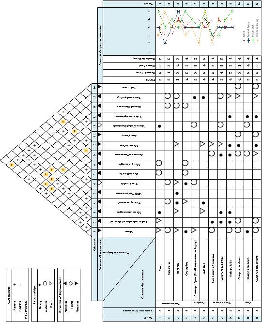
This process identified three key negative correlations to focus on: Cost vs. Biodegradability, Durability vs. Biodegradability and Strength vs. Biodegradability. This resulted in a crucial choice to make to confirm the direction of the project, either to maintain the important biodegradability of the project and compromise the three other criteria or to compromise to recyclable materials that can be cheap, strong and durable. Because the suspension is so closely linked to safety of the vehicle, the choice was made to use recyclable materials and leave many of the non-structural/cosmetic components in the rest of the vehicle to be biodegradable. This aligns with the findings of the material comparison matrix in section 3.3.
5 CONCEPT CREATION AND SELECTION
5.1 CONCEPT SKETCHES
Based on resources initially studied in Section 3.2 and morphological analysis techniques (15), the following sketches were produced to create a pool of ideals for selection and comparison at a later date. In multiple cases, suspension concept sketches were created from well-established engineering solutions currently in the market place such as the Lexus IS200 (16) or Smart ForTwo (17).
5.1.1 MacPherson Strut Layout
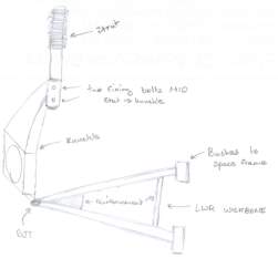
Figure 6 Sketch for MacPherson Strut Concept
The MacPherson strut is the most commonly used suspension type on the front (9). This concept uses the key principles of the design: a lower wishbone, upright and suspension strut and damper combination. The lower wishbone is mounted to the upright via a ball-joint which allows free rotational movement in all axes, labelled BJT in Figure 6. The fixing bolts on the strut securely fasten it to the upright so they act in unison.
5.1.2 Double Wishbone Layout
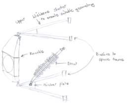
Figure 7 Sketch for Double Wishbone Concept (Lower)
The double wishbone arrangement appears on vehicles in multiple forms, the two most common being with the strut attached to the lower wishbone or lower joint of the suspension as seen in Figure 7, or attached to the upper wishbone as shown in Figure 8. The style with the strut connecting to the lower wishbone is often favoured to save on packaging space. Double wishbone layouts are generally more tuneable than other options but are larger in size.
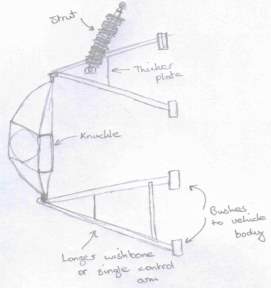
Figure 8 Sketch for Double Wishbone Concept (Upper)
5.1.3 Trailing Arm Layout
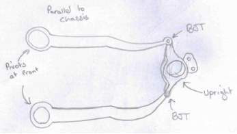
Figure 9 Sketch for Trailing Arm Concept
The trailing arm suspension concept in Figure 9 is similar to the double wishbone arrangement shown above. However, instead of the two control arms being wishbones protruding out of the body, the trailing arms run parallel to the body, thus saving space. This could be beneficial in the POLIS vehicle due to its small track width.
5.1.4 Rack and Pinion Steering Systems
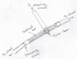
Figure 10 Sketch for Rack and Pinion Concept
The rack and pinion steering system in a simple and inexpensive way to translate the steering wheel movement into movement at the wheels making it the most common system in use today. The steering shaft ends with a pinion gear that interfaces with a toothed bar on the steering rack, as the shaft is rotated, this connection pushes the bar left and right as seen in Figure 10. More complex systems build on this fundamental principle but allow the driver good steering feel.
5.1.5 Pitman Arm Steering Systems
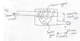
Figure 11 Sketch for Worm and Sector Concept
The worm and sector is one of multiple steering box configurations that use a pitman arm. The pitman arm, as labelled on the right of Figure 11, is connected perpendicular to the track rod as shown displayed in Figure 12. The different steering box designs work in similar fashion by translating the rotational movement of the steering shaft to angular displacement of the pitman arm and therefore track rod.
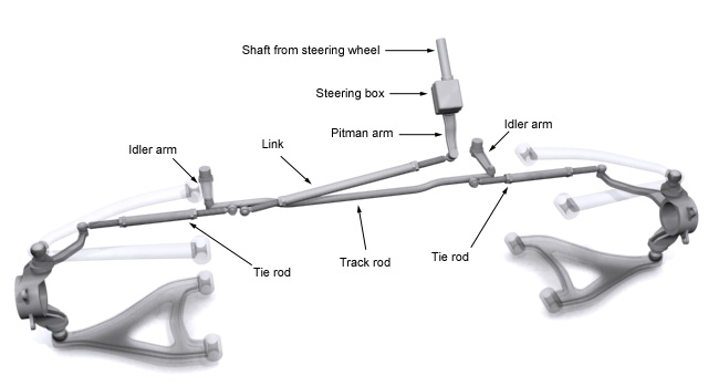
Figure 12 Pitman Arm Steering System (18)
The sketches above are key items that formed the basis for the direction of the project, further discarded concept sketches can be found in APPENDIX A along with detailed sketches of individual components and fixtures.
5.2 SELECTION PROCESS
A selection matrix, Table 2, was utilised to differentiate between the various common layouts for front suspension. A small pool of car owners in the potential market for POLIS vehicles were asked to rank the criteria and therefore provide a representative weighting for each between 1 and 5. The current double wishbone system with suspension strut mounted to the lower wishbone was used as the datum and all other layouts were given values from -3 to +3, where +3 is best vs. datum of 0, and -3 is the worst.
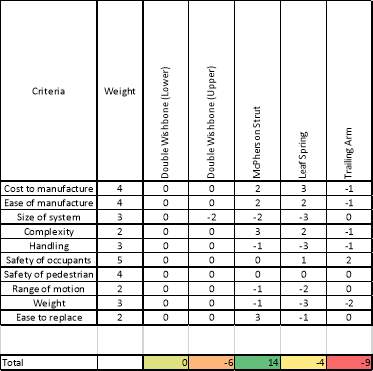
Table 2 Suspension Layout Selection Matrix
Table 2 shows the totals for each layout in the lower row, this was the sum of each criterion value multiplied by its weighting. The trailing arm layout was highlighted as the worst option, primarily due to its poor handling characteristics and manufacturing issues.
The McPherson strut shined through as the favourable choice, being the only layout to total higher than the datum. This is mainly attributable to its simplicity and cost which are both weighted heavily in this project.
There was a consideration to produce the lower wishbone out of two metal sheets and spot weld them together to produce a stiff box section. However, steel is the best material choice for this application for weldability and material strength. The use of steel goes against the ethos of the project and therefore a single cast aluminium wishbone was chosen.
6 DEVELOPMENT
After defining the direction of the project and performing comprehensive methods of selection to identify the most suitable systems, further development was required. This was achieved through the use of CAE and modelling, prototype manufacture and DFMA analysis.
6.1 DETAILED MODELLING AND ASSEMBLY
In order to manipulate and visualise concepts in three dimensions, solid modelling was performed on Catia v5. The software also allows for manufacturing drawings to be created from the 3D model. Bringing together separate solid models into an assembly provided the ability to perform interference and clearance checks, investigate packaging space and visualise the dynamics of the suspension system.
6.1.1 Production Intent Model
Modelling for the mass production components was an iterative process and linked to concurrent analysis techniques in section 7.1.
Upright
The front uprights on the 2015 POLIS vehicle were of a boxed style aluminium construction, Figure 18, designed for machining and rose joint connections to the wishbones. Due to the new MacPherson strut suspension layout on the 2016 POLIS vehicle, the uprights shown in Figure 13, needed to accommodate a ball-joint connection on the bottom and a bracket connection to the strut on the top. Additionally, the effort was made to design the upright with respect to the proposed production method, covered in detail in section 6.3.1, also saving weight where possible.
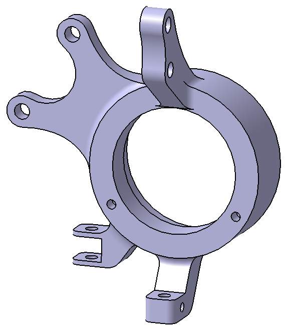
Figure 13 Production Intent Upright Catia Solid Model
Wishbone
Much like the upright, the lower wishbone had similar functions to those in the 2015 model but would be designed with increased emphasis on manufacturing considerations. Automated design optimisation was implemented on Catia v5 to maximise the strength to weight performance of the wishbone. The program automatically ran various iterations of the design based on constraints and parameters input into Catia, this yielded much faster and optimised results than making manual changes and retesting to access the effect of each change. The final solid model is displayed below in Figure 14.
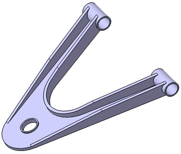
Figure 14 Production Intent Wishbone Catia Solid Model
The technical drawings for the production intent upright and wishbone can be found in APPENDIX B, in addition to technical drawings of the full production intent assembly.
Minor components and adjustment to further components
Once a dimension range for the critical components had been confirmed, in part with the Lotus Shark analysis in part 7.1.3, the remaining components could be adjusted to fit their new roles within the system. A lower ball-joint was also modelled in an inclined state.
- Lower Ball-joint
- Spring/Damper
- Spindle
- ARB
- Bushings
Certain components of the previous years’ development were carried over to ensure compatibility and reduce workload. The brake disc, calliper and pads remained unchanged as it was judged that brake torque produced by these components exceeded the requirements of the POLIS vehicle. 3D models of the other components can be found in APPENDIX C.
The components shown above are the final models that would go on to be manufactured, prior to this, each component underwent 4+ iterations. The different iterations of upright are shown in Figure 15.
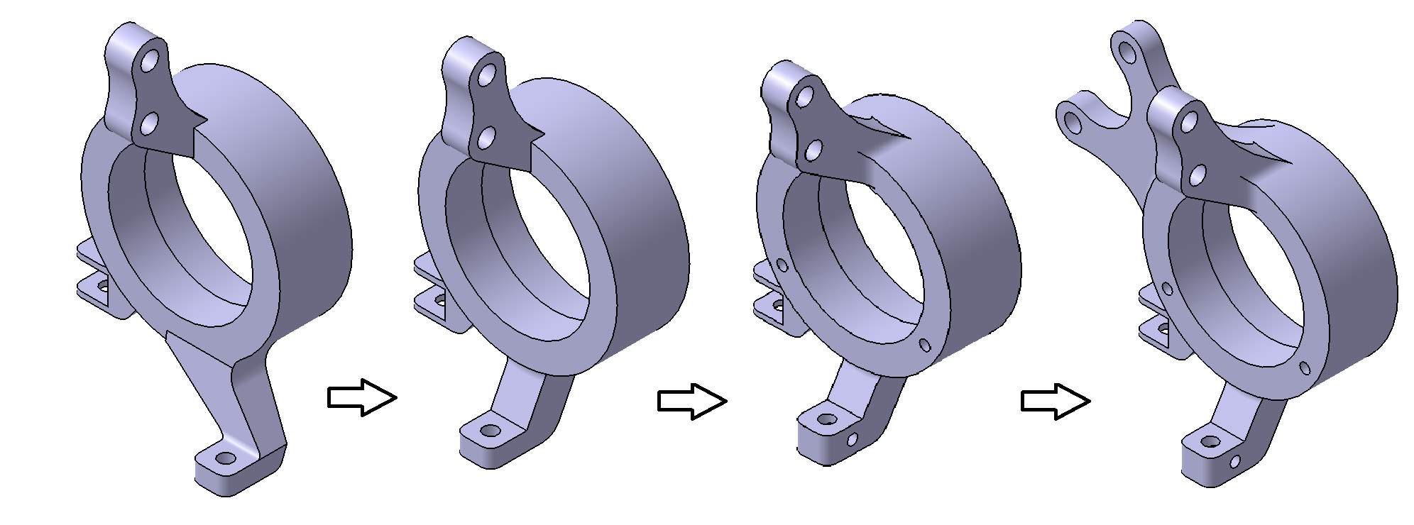
Figure 15 Production Intent Upright Iterations
6.1.2 Prototype Model
The methodology behind the design of the prototype models was to create an upright capable of being manufactured on a 5-axis CNC machine and a set of wishbones easily fabricated from readily available materials.
Upright
The prototype upright on the 2015 POLIS vehicle were heavy and made from aluminium box sections, shown on the left of Figure 18. The prototype upright for the 2016 POLIS vehicle, shown in Figure 16, was designed through an iterative process ensuring that weight was saved as much as possible without compromising strength. The sweeping, smooth design below is a result of removing stress concentrations in the upright and using as much of the aluminium’s strength as possible in the most relevant places. Because the part was designed for machining, mould flow did not need to be considered. The prototype upright was designed to be as close to production intent as possible and only the top mount to the upper wishbone is different. The technical drawing for the prototype upright can be found in APPENDIX B.
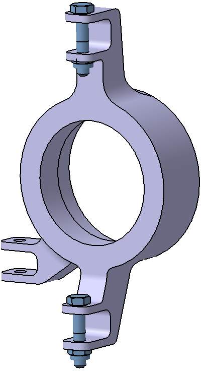
Figure 16 Prototype Upright Catia Solid Model
Wishbones
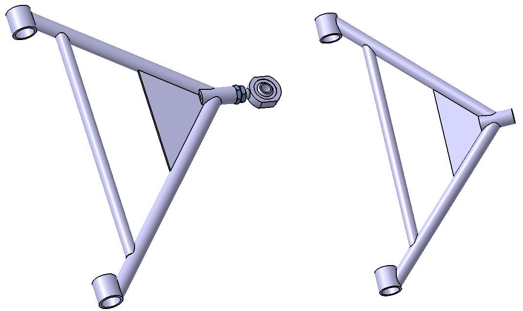
Figure 17 Prototype Wishbones Catia Solid Models
Figure 17 shows the prototype lower wishbone on the left and the upper wishbone on the right. The fixings are also displayed on the lower wishbone to provide an understanding of the connection type applied. Threaded rose joints were chosen as opposed to pressed in ball-joints as with the production intent models, this was due to University manufacturing capabilities. The design also elegantly used tubing and the rose joints already used within the University as they were perfectly suited for the application. This saved both time and money which are both key considerations when developing prototype parts. The technical drawing for this component can be found in APPENDIX B.
6.2 PROTOTYPE MANUFACTURE
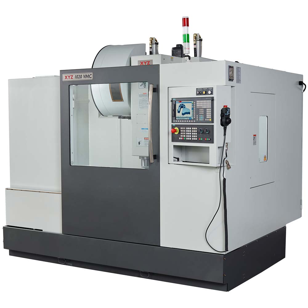
Two prototype aluminium uprights were manufactured for this project on the University’s XYZ 1020 VMC 5-axis CNC machine, shown in Figure 19. Images of the completed prototype parts and assembly can be seen in APPENDIX D, the finished upright can be seen on the right of Figure 18 with the previous year’s upright on the left.
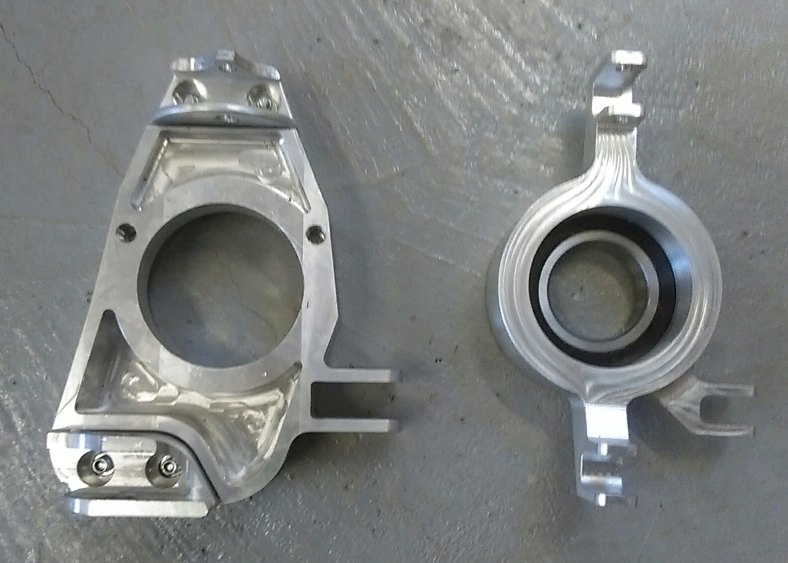
Figure 18 Finished Prototype Upright (Right) vs. Old Upright (Left)
Prior to manufacture on the 5-axis CNC machine, the prototype concept was planned to be manufactured on a Denford 2600 Pro 3-axis CNC router. The Catia file was converted into .igs solid model format and imported into Denford VR (19), this allowed the billet to be input and the machining process to be visualised. Furthermore, Edgecam (20) computed the tool path required that would be possible with the Denford machine. After multiple approaches, it was concluded that the 3-axis machine would not be able to create the designed part.
The primary reason for this was that the part was designed for not only machining but also to serve as a suitable representation of the production intent part which would be cast. This meant there were multiple undercuts put in place and curved surfaces to maximise weight saving and reduce stress concentrations respectively, as mentioned in section 6.1.2.
The virtually finished part is shown in Figure 20 below, when machined to its larger face for an initial roughing cut, using a 3mm end mill. From this state, it is not possible to rotate the part to remove undercuts and also securely support the machined piece.
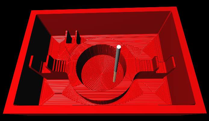
Figure 20 Incomplete Machining Visualisation from Front
As a separate approach, the machining was simulated cutting down from the side surface. This offered similar issues regarding the undercuts and is shown in Figure 21. This visualisation is after the second operation, finishing, using a ball-nosed slot drill.
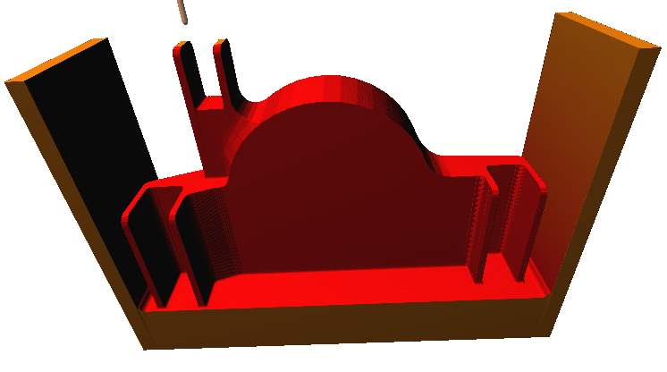
Figure 21 Incomplete Machining Visualisation from Side
APPENDIX D contains multiple further images of the visualisation and checks carried out for the Denford 3-axis CNC machine, including tool path failures. The more sophisticated XYZ 5-axis CNC machine was chosen to avoid the problems above, the rotational axis could remove all material where necessary and perform these operations with higher precision and surface finish.
The final prototype upright was manufactured in four distinct stages:
- Main Shape – The shape without undercuts was machined from the billet using a 16mm end mill roughing cut, 10mm end mill semi-finishing cut and 10mm ball nose to reach the enclosed pockets and provide a smooth surface finish on all surfaces including the tight radii.
- Undercuts – The undercuts from the first stage were machined using just the 10mm ball nose. This gave the part a good surface finish immediately.
- Holes – The 8mm holes for the suspension member tie rod joints were machined by peck drilling. This was to aid in preventing chatter and swarf build up. Most importantly for this application peck drilling also helped confirm parallelism between the two holes in each case.
- Lathe – The inner 90mm diameter hole is used to pressure fit the bearing which has a high tolerance. For this reason, it was performed on a lathe to closely control this tolerance which would not be possible on the 5-axis CNC machine.
6.3 DESIGN FOR MANUFACTURE
6.3.1 Production Intent Model
One of the key benefits of mass production is the ability to amortise a high cost of tooling across a larger group of parts, to spread and therefore reduce the cost per component. Casting is perfect for mass producing uprights and is widely used throughout the industry. Machining is slow and mostly used for smaller scale processes due to its good quality surface finish and tolerance control. Neither of these two elements are a priority in a structural part such as the upright thus the faster and more efficient casting process is preferable.
Casting allows for more complex and lighter upright designs as it occurs during one single process as opposed to machining, which can occur in multiple phases and therefore increase cost. As many features as possible will be cast into the upright to reduce the associated costs of machining post-cast however, the increase in complexity is likely to result in issues with mould flow. As shown in Figure 13, the upright has been designed to have a consistent thickness throughout, this ensures there are no large step changes in thickness which result in poor mould flow and therefore a poor quality cast. As shown in Figure 22, the ball-joint connection is a testament to this, it is much thicker than the machined prototype version and has been designed to allow for good flow throughout the component. Despite being a more expensive fastener the ability to just cast this area without a follow up machining process greatly reduces cost.
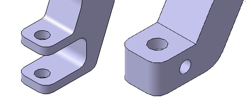
Figure 22 Upright Lower Joint Prototype (Right) vs. Production Intent (Left)
The production intent wishbone used similar principles when using the automated design optimisation, parameters were put in place to ensure the wall thickness was consistent and that the aluminium could flow well through the component.
6.3.2 Prototype Model
The aim for the prototype model was to remain as close as possible to the mass production version of the components but while respecting the technical limitations of the University. The largest deviation from production intent is in the suspension layout itself, a MacPherson strut layout was not feasible with University resources so a double wishbone configuration was adopted.
The wishbones were designed to be easily fabricated from the resources available to minimise upfront cost. The tubing used was bought in bulk for various projects and is extremely strong for its purpose, thus meaning that very little redundancy needed to be implemented into the design. The “A-shape” tubing results in simple angles to be notched and the use of smaller separate tubes for each joint results in a longer stronger welding bead which is easy to weld.
The bearing manufacturer and multiple academics were consulted to find the correct tolerance for the inner surface of the upright. This was crucial to interface correctly with the bearing, a press fit was required and therefore the component was cut to H7 tolerance because the bearing was manufactured to a p6 tolerance, yielding a suitable interference fit. This was performed with a separate lathe operation and is detailed in section 6.2.
6.4 DESIGN FOR ASSEMBLY
The primary reason for DFA was to ensure mass production assembly was performed easily and cheaply. When modelling, this was simply done using a common axis on all components, this meant that when bringing all components into an assembly they all appeared in their correct place in the system, by default.
When on the production line, it is important the parts are designed to fit together easily and correctly to reduce the time and consequently, cost. Poka-yoke (21) part of a Japanese lean manufacturing system to reduce, detect or highlight human error. Some poka-yoke features have been implemented into the production intent components of the POLIS vehicle. Notably, the upright joints are offset to prevent incorrect connecting the upright upside down. There is also an L or R, for left and right respectively, stamped into a visible area of the aluminium to safeguard against placement on the incorrect side of the vehicle.
The upright calliper mount is based on a standard 2.38” lug mount (22) hence, can facilitate multiple common parts, this reduces reliance on a single calliper and can be interchangeable on the same production line with multiple vehicles using the same mount. This again offers huge time and financial savings.
The lower wishbone on the production intent model reduces the number of parts used in the assembly by consolidating the two lower control arms and handling both the lateral and longitudinal movements of the upright. Reducing the number of parts in this way also has a knock on effect of “less purchases, inventory, handling, processing time, development time, equipment, engineering time, assembly difficulty, service inspection, testing” (23).
7 ANALYSIS
Multiple computer software packages were used to analyse the solid models created for both the theoretical production intent and prototype components.
7.1 THEORETICAL ANALYSIS
Computer analysis for the theoretical version is required to be as close to reality as possible considering the manufacture of production intent parts was not feasible. For this reason, suspension analysis was performed on Lotus Shark to gain a high quality understanding of how the vehicle is likely to behave in the real world. Finite element analysis was also performed on two separate software packages to allow for comparison between the two.
7.1.1 CATIA .v5 Finite Element Analysis
Ultimately, FEA is an approximation based on inputs and it was noted that to gain meaningful results from the analysis, realistic loading conditions had to be calculated. Loads within a suspension system are extremely complex, for the FEA multiple forces were consolidated into single forces and moments to simplify the solution and save on computing time.
In all cases, the force was applied to the bearing surface and the model was constrained at the lower wishbone joint, suspension strut joint and outer tie rod joint. Because all joints allow rotation under load, constraints were not applied to the rotation in any plane. Assuming the load is instant, the strut holds the top joint of the upright stationary in all planes because the spring will deflect vertical motion. The lower wishbone limits the upright’s movement laterally and longitudinally but allows it to move vertically, therefore the model was constrained in x and y but left free in z. The outer tie rod to the steering rack only limits lateral movement so the model was constrained in the x direction but left free in y and z.
Three loading conditions were simulated for the upright. The forces under braking, bump and forces under braking during a corner. This was judged to sufficiently capture the performance of the upright. Maximum cornering velocity of the POLIS vehicle without toppling was calculated from equation (1) where r = radius of turn, g = 9.91m.s-1, b = half the track width and h = CoG height.
| Vmax=rgbh | (1) |
The lateral acceleration of the vehicle just before topple was then calculated from Gillespie’s (24) equation (2) below, where, Fy = Lateral cornering force, M = Vehicle mass and Vmax found in equation (1).
| Fy=MVmax2r | (2) |
A conservative value of lateral force was then calculated using a safety factor of 1.2x total vehicle mass. This resulted in a worst case moment on the outside wheel of 585Nm.
The force acting on the vehicle under braking was calculated using fundamentals of mechanics to estimate the weight transfer and was found to be 2549N. All calculations and associated values can be found in APPENDIX E.
The results for the loading conditions under braking are shown in Figure 23, below. The colour graph shows the areas of highest stress to be at the base of the top connection to the suspension strut. The highest value given of 48.8 MPa is well below the alloys yield strength of 280MPa, this means it could undergo multiple fatigue cycles and exceed the life of the vehicle. FEA results for previous iterations of the upright, APPENDIX E, display the benefits of the fillets and smooth edges on dispersing stress concentrations as well as the advantages to casting flow detailed in Section 6.3.1.
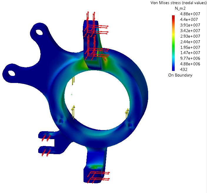
Figure 23 Catia von Mises Stresses under Braking
The Catia v5 results for the maximum braking and cornering conditions are shown below in Figure 24, the bending moment produced by the lateral force acting on the tyres heavily influences the stress concentration on the upright. Despite experiencing a considerably higher maximum stress of 117MPa when compared to braking alone, the stress is well below the yield strength of the alloy.
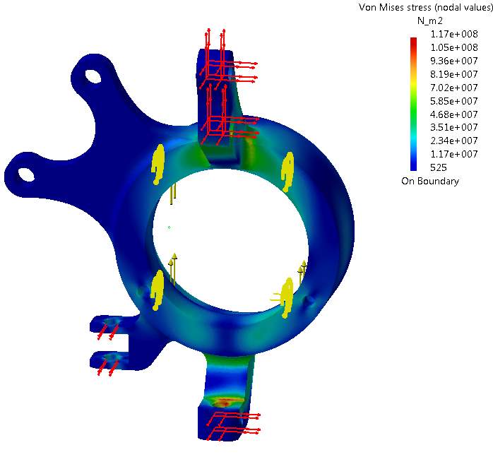
Figure 24 Catia von Mises Stresses under braking and cornering
Considering the assumed infrequency of this style of loading in service, the design was judged to be extremely safe and unlikely to fail within the lifetime of the vehicle.
Lower Wishbone
The lower wishbone in a MacPherson strut system is generally free from many excessive forces throughout its life. The wishbone was analysed statically with the inboard bearing surfaces locked in all three degrees of freedom and a force applied to the ball joint end to simulate a worst case cornering compression case shown in APPENDIX E. The stress was found to be 32.3MPa, significantly below the yield strength of the aluminium.
The main concern for the wishbone was vibrations from the road and engine, Catia v5 frequency analysis was used to estimate whether the wishbone would not resonate at any common frequencies and therefore cause NVH issues in the cabin.
The wishbone was set up with the inboard bushing side locked and with the un-sprung mass applied to the ball joint end. From this simulation 6 natural frequency modes were found within the wishbone. If the wishbone resonated with the engine vibrations or road frequency at these points it would cause great discomfort to the driver. The following frequencies in Table 3 should also be avoided due to their effects on the human body listed on the right.
| Frequency | Human Response |
| 5Hz | Vital organs resonate (including stomach – causing nausea) |
| 25Hz | Human head Resonates |
| 30-80Hz | Human Eyes Resonate |
| 50-200Hz | Difficulty steering |
Table 3 Human Responses to Vibration (25)
A standard vehicle engine will have damping between the engine vibrations and the cabin but because the POLIS vehicle will be electric these vibrations will not occur, instead the primary vibration source will be from the road profile.
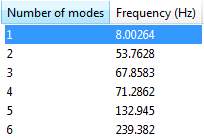
Table 4 Wishbone Natural Frequency Modes
Taken directly from the Catia data, Table 4 shows the Natural frequency of the wishbone under full load is roughly 8Hz. The Nankang AS-1 155 55 14 69V (26) tyre spring rate is much higher relative to the suspension spring, the suspension spring is the dominant feature to establish the ride frequency. “The best isolation is achieved by keeping the natural frequency as low as possible. For a vehicle with a given weight, it is therefore desirable to use the lowest practical suspension spring rate to minimize the natural frequency” (24).
Because the stresses experienced in both components are considerably below the aluminium yield strength, they are to be expected to last between 1×10⁴ and 1×10⁹ cycles based on fatigue design curves for 6061-T6 aluminium (27).
7.1.2 ANSYS Finite Element Analysis
Further analysis within ANSYS workbench 17 was performed to expand on the upright analysis from Catia v5’s inbuilt FEA package. This is because the loading case on the upright is more complex than the wishbones. The model constraints and loads were applied in the same way and the mesh and material properties were kept consistent. The higher stress found from either Catia v5 or ANSYS would be taken forward to act as the conservative worst case scenario.
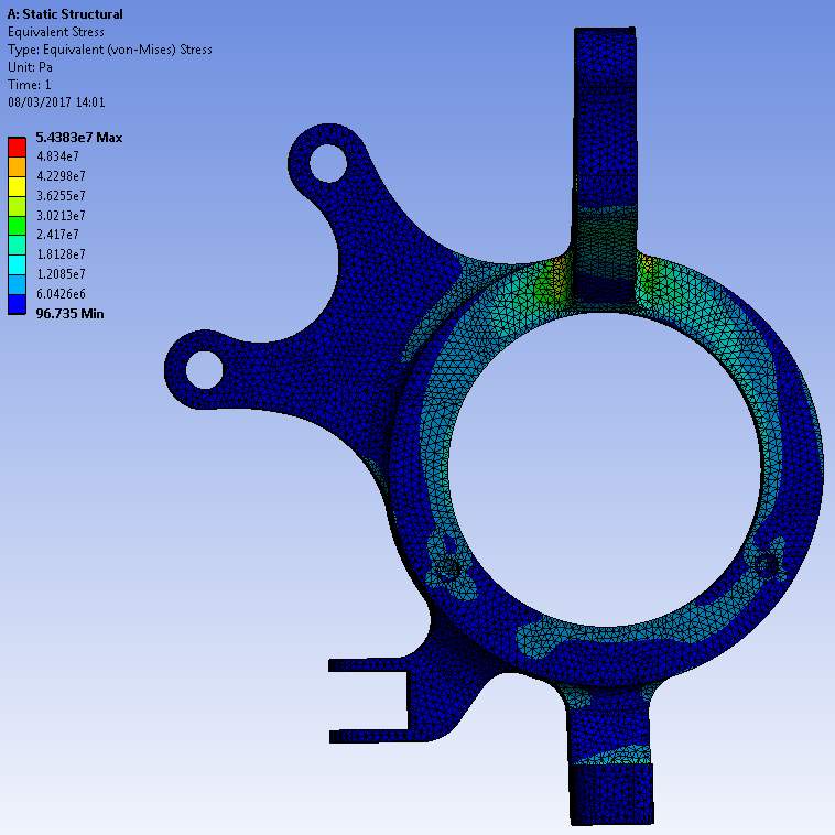
Figure 25 ANSYS workbench von Mises Stresses under Braking
The ANSYS analysis for the braking only loading case, shown above in Figure 25, yielded a slightly higher maximum stress of 54.4MPa with a similar but more detailed colour map showing stress concentrations. The results validate the design decision to use multiple fillets in key areas and sweeping lines. It shows the load from the road under braking being correctly distributed throughout the component.
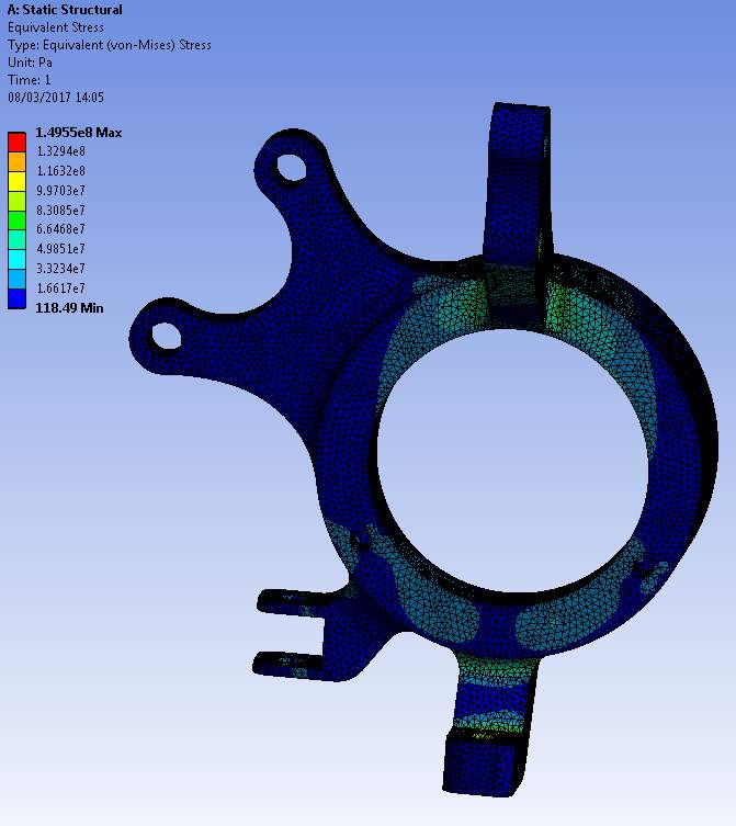
Figure 26 ANSYS workbench von Mises Stresses under Braking and Cornering
Figure 26 displays the ANSYS results under both braking load and cornering moment. A maximum of roughly 150MPa is considerably below the alloy yield strength of 280MPa. The high stress is shown on the lower joint to the lower wishbone, this was to be expected due to the reaction force from the tyre/road contact on the outside wheel compressing the joint.
Comparison between Catia v5 and ANSYS workbench is shown in Figure 27 demonstrates ANSYS software being consistently higher than Catia. This could be due to ANSYS being developed for FEA and therefore having a more detailed solver however this discussion is not within the scope of this project. However, in conclusion, the higher stresses given by ANSYS will be trusted as a necessary precaution as the component is safety critical.
Figure 27 also included the 2015 POLIS upright, which was tested under the same conditions, for comparison. The more complex cornering and braking condition, which includes a lateral moment, is shown on the right. It is clear that the new upright can be expected to experience much lower internal stresses under this combined loading than previously (185%) as well as offering a nearly 58% (901g) decrease in mass.
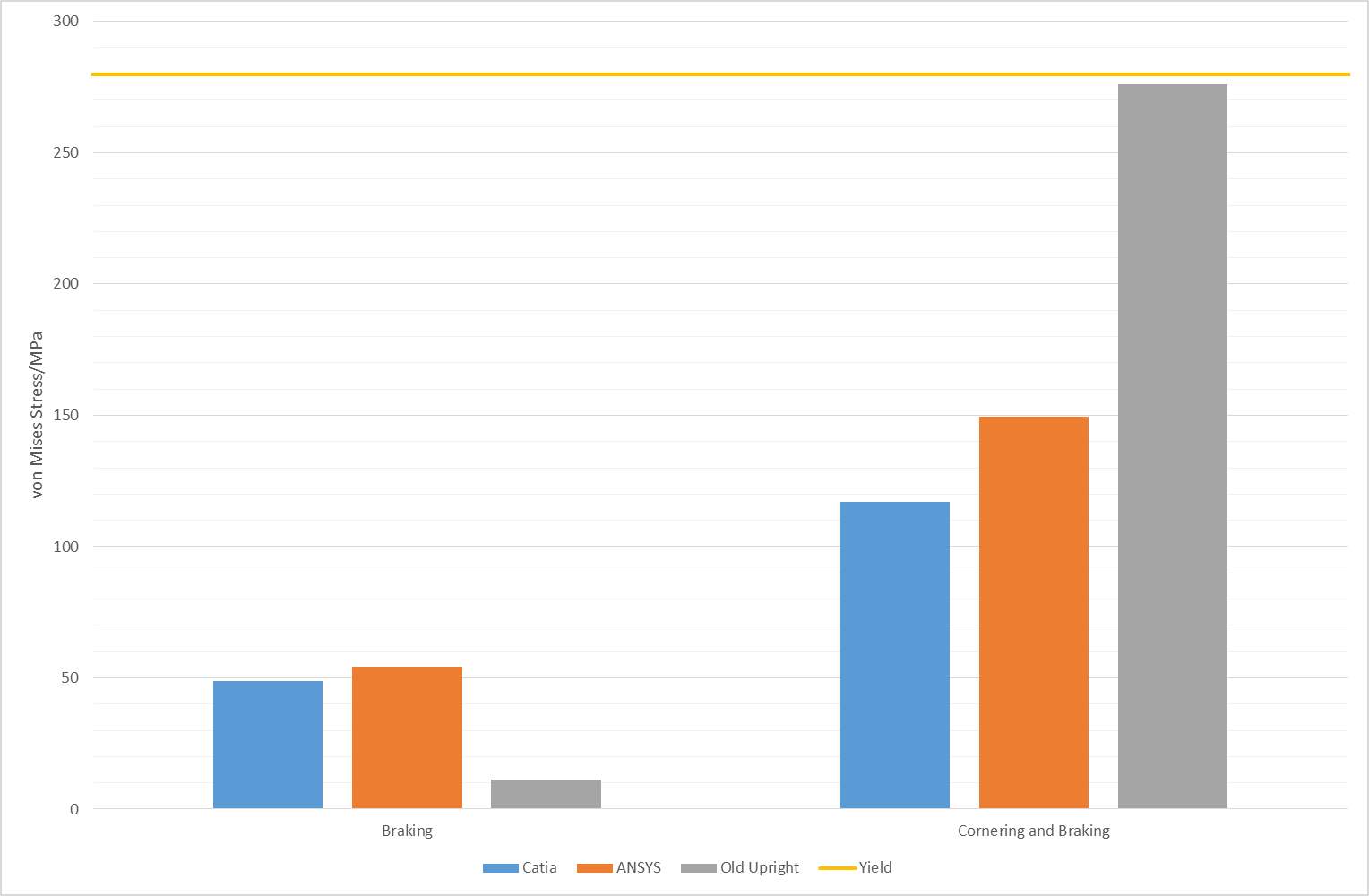
Figure 27 Catia and ANSYS comparison chart: von Mises Stress vs. Software package and Model
7.1.3 Lotus Suspension Analysis
To correctly understand the dynamic responses of the suspension on the POLIS vehicle, Lotus Shark suspension analysis was used. The software required the coordinates of the suspension modelled on Catia to be manually input as well as the mass and CoG data for the components and body, which can be found in APPENDIX F. From this information, the software could simulate the suspension in three modes: Bump, roll and steer. Due to the dimensions of the POLIS vehicle, with high CoG and short track width, the roll and steer cases were of the most use for design.
Figure 28 shows the suspension geometry displayed in Lotus Shark, statically on the left and under full lock on the right. This was performed as an additional check to ensure all dimensions were correct and the POLIS vehicle can produce sufficient steering lock for a city vehicle. The simulation ran up to 33° of steering and highlighted no issues with the geometry set up chosen.

Figure 28 Lotus Shark Suspension Steering Analysis
The roll of the vehicle was also simulated to assess how well the POLIS vehicle would react to body roll. From multiple iterations, the author found a suitable king pin inclination angle, KPI, and spring stiffness for the MacPherson strut. The vehicle at 5° of body roll is displayed in Figure 29.
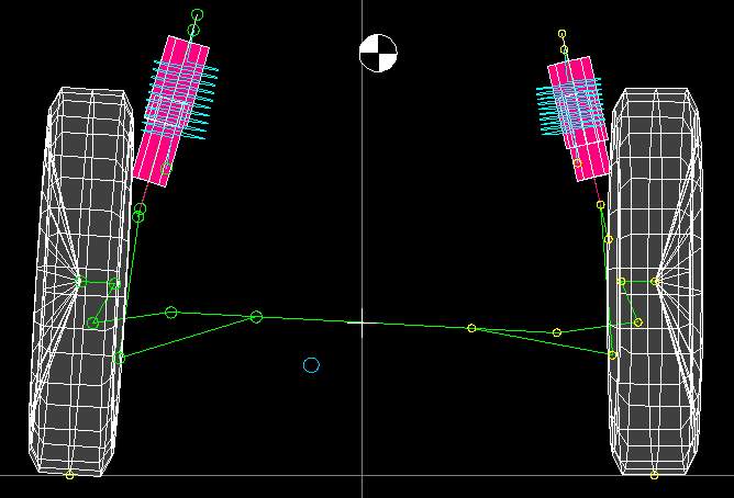
Figure 29 Lotus Shark Suspension Roll Analysis
The roll centre of the vehicle is shown as the light blue circle below the steering rack and the CoG of the body is shown as the 4-quadrant calibration mark between the two suspension struts. As the body rolls right, the CoG marker moves right and the roll centre moves left. Further dynamic testing cases performed on Lotus Shark can be found in APPENDIX F.
7.2 PROTOTYPE ANALYSIS
The loading cases experienced by the prototype model were expected to be extremely different from the theoretical version of the vehicle. The prototype was not to be expected to reach any high speeds and the range of motion was very limited in comparison to a theoretical version. Above all, the prototype was to be considered a visual representation of the vehicle and would only be required to support its own weight and that of two occupants at the same time as driving and manoeuvring at low speeds. There also needed to be a margin of safety with all calculations to ensure safety and also to allow for modifications to other areas of the vehicle in the following years, which could potentially increase the overall mass.
7.2.1 CATIA .v5 Finite Element Analysis
For the reasons mentioned above, simplified loading cases and constraints were applied in Catia v5 FEA package to analyse the strength of the components. For the upright, constraints were the same as those used with the theoretical upright in Section 7.1, the component was locked in place at the upper and lower suspension joints and tie rod connection.
The rose joints used in the prototype provide fixed DOFs in x and y. Because the system is double wishbone rather than MacPherson strut the suspension spring is acting on the lower wishbone rather the top of the upright. In terms of constraints, this meant the lower joint of the upright was locked in the z direction but the upper joint was left free to move, due to the rotation of the wishbone. The tie rod joint constraints were the same as with the theoretical version, only locked in the x direction and free in y and z.
The force from the weight of the vehicle and occupants was applied to the central bearing surface. Due to the low acceleration experienced by the prototype, this was judged to be a suitable representation of load on the upright, as no load transfer would occur at low speed. A larger safety factor of 1.5x total vehicle mass was used to cover any unexpected forces acting on the upright. The calculated force was 8190N including two occupants.
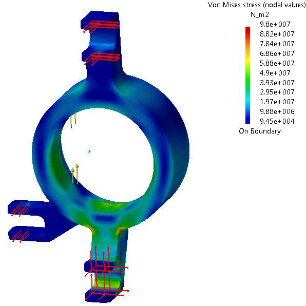
Figure 30 Catia von Mises Stresses of Prototype Upright
Figure 30 shows the stress concentrations are focussed on the bottom arm of the upright as opposed to the top with the theoretical upright. This is purely due to the position of the suspension strut and the resulting constraints on the model. The design could possibly be improved by increasing the radius on the fillets highlighted red on Figure 30. However, this was judged to be an unnecessary change as the yield strength of the material, 280MPa, already greatly exceeds the predicted stresses of 98MPa in Figure 30.
The pivoting of the upper wishbone results in it seeing very little force at such low speeds, the lower wishbone is the main component between the downward force of the vehicle weight through the suspension strut and the resultant force from the ground through the upright’s lower mount. The upper wishbone only has to react to the secondary forces created by the moments on the wheel and thus keep it upright. A free body diagram was created and the resultant net force was calculated to be only 43.8N of compression, this calculation can be found in APPENDIX E. Figure 31 shows a very small stress of 1.47MPa which is well below the compressive yield of the steel which is assumed to be close to the tensile yield of 245MPa (28).
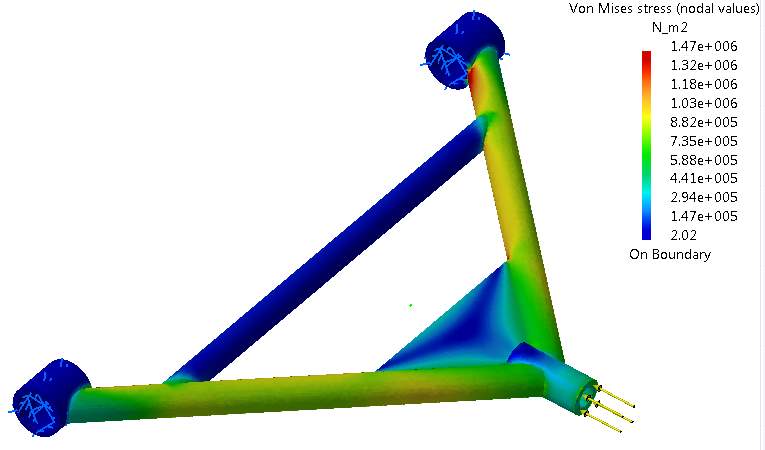
Figure 31 Catia von Mises Stresses of Prototype Upper Wishbone
The lower wishbone was analysed by clamping x, y and z at the body mounting surfaces and the connection to the upright. The load from the vehicle weight was directed onto the wishbone plate at an angle to simulate the load paths created by the suspension during compression.
The force value used for the load was the full prototype mass (395kg) plus the mass of a 95th percentile male (102kg) and 5th percentile female (49kg), all with a safety factor of 1.2. Weight distribution was considered to provide a force through the suspension strut of 1474N, this was broken down into y and z components of 382N and 1242N respectively, to provide the correct resolved force at the correct angle onto the wishbone.
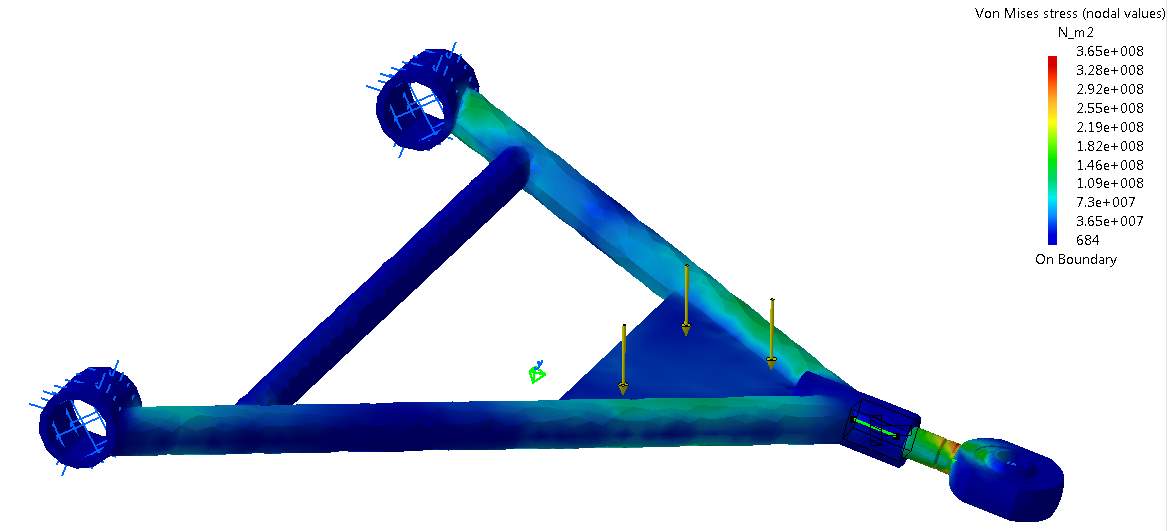
Figure 32 Catia von Mises Stresses of Prototype Lower Wishbone
Figure 32 displays the results for the criteria listed above, the assumed yield and ultimate tensile strengths for the mild steel used in this wishbone are 245MPa and 450MPa (28) respectively. It is clear that, with Catia predicting a stress of 365MPa in the wishbone, it would yield under these conditions. The loading conditions used were intended to represent a worst case scenario, thus can be expected to be an extremely unlikely condition.
However, to safeguard against component failure the recommendation is that the wishbone design is suitable for use in the vehicle without the battery or rear passenger. This reduces the total mass including 95th percentile male to be 417kg. If at any point the mass is to be increased or the battery is sourced, the wishbone should be reanalysed and potentially redesigned.
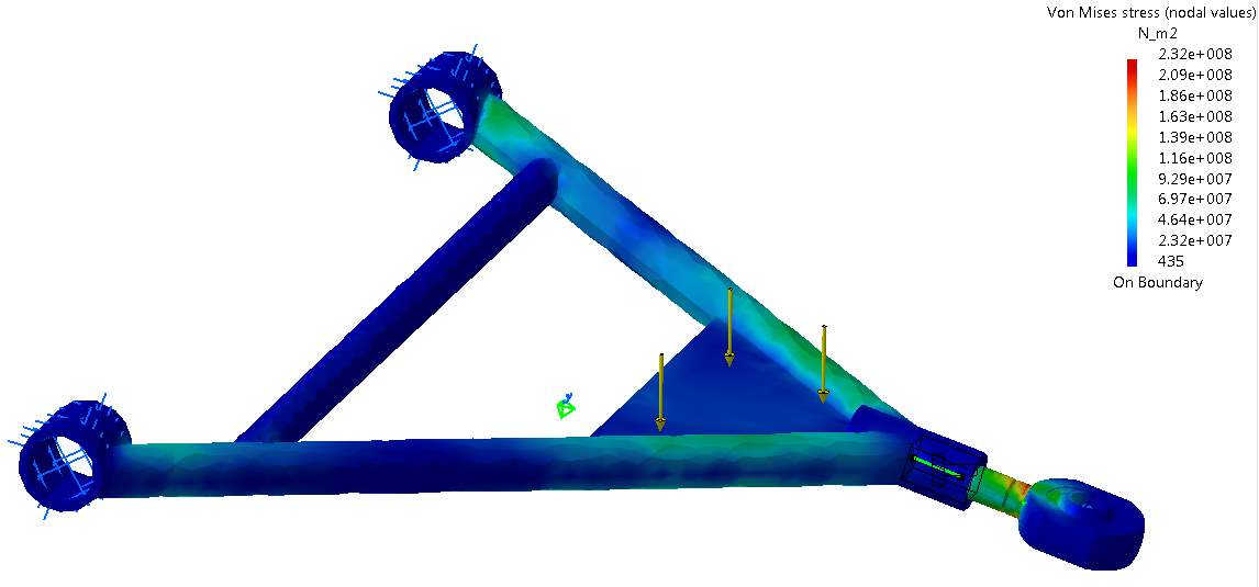
Figure 33 Catia von Mises Stresses of Prototype Lower Wishbone (without psgr or battery)
The stress experienced by the wishbone without the passenger or battery is shown clearly in Figure 33 to be 232MPa which is below the yield point by a sufficient margin. With the safety factor implemented this design was judged to be suitable for fabrication.
7.3 FAILURE MODE AND EFFECTS ANALYSIS
Design FMEA is an analysis technique to identify any potential problems that may arise when releasing a product. The analysis is performed in a matrix where all components of the system are listed and all problems and their potential causes and effects are reviewed in detail. A numerical tag is then assigned to each property, the severity of the problem if it occurs, the likelihood of the occurrence and the ease of detection prior to occurrence. D-FMEA was carried out by the author for the production intent components on the POLIS vehicle front suspension.
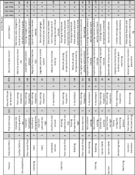
The severity, likelihood of occurrence and likelihood of detection criteria were taken from an International Journal of Research in Engineering and Technology concerning FMEA (29) and can be found in APPENDIX G. Table 5 shows the Design FMEA matrix created for the POLIS vehicle front suspension.
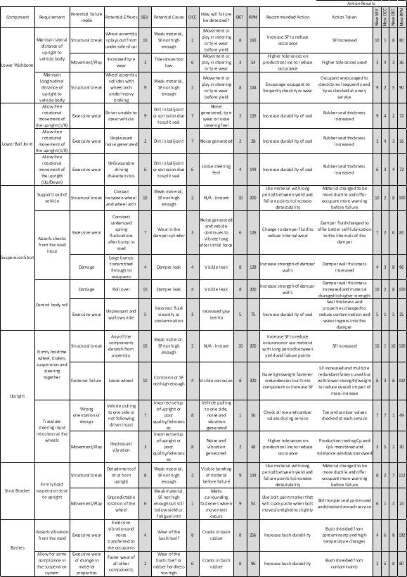
Advanced FMEA was also performed on the casting process for the upright, this was to gain understanding of the key considerations when casting the upright. Because this process was carried out in advance of manufacturing the upright on a mass production scale, the potential effects, causes and recommended actions are hypothetical and should be treated as such. The P-FMEA for the upright will have similar considerations to that of the wishbone due to a very similar casting process and material being used. The P-FMEA matrix is shown below in Table 6.
7.4 COST ANALYSIS
To estimate the total cost per part, both for the production intent components and prototype components, synthetic cost analysis was performed. The values given are estimated and should be treated as such, factors of error are present from the assumptions made, industry averages used and the CAE. Material prices were correct as of April 2017.
7.4.1 Mass Production Cost
The speculated production volumes of the Honda Goldwing are 12,000 annually, this is a commonly estimated figure as Honda does not readily disclose production volumes. Similar city cars produce volumes ranging from less than 1000 annually with the Renault Twizy to 4,130 Smart EVs annually. Furthermore, the larger but more popular Nissan Leaf had 47,484 sales in 2013 (30). Based on these figures and the goal to mirror the Honda Goldwing with the POLIS project, a nominal value of 12,000 vehicles per year will be used.
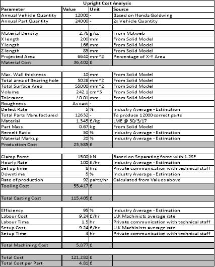
Table 7 Production Intent Upright Synthetic Cost Analysis
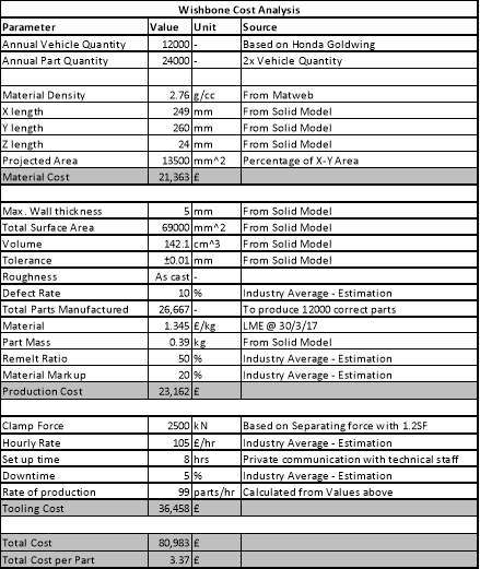
Table 8 Production Intent Wishbone Synthetic Cost Analysis
Table 7 and Table 8 display the synthetic cost analysis performed to estimate the cost to produce the upright and wishbones, respectively. The total cost of an upright is assumed to be £4.81 and the total cost of a wishbone, £3.37. This value does not include costs for assembly of the components together on the production line, solely individual manufacturing processes.
7.4.2 Prototype Cost
A rudimentary cost analysis method was used to estimate the total cost of prototype parts. For the aluminium uprights manufactured on the 5-axis CNC Machine the cost was calculated as shown in Table 9:
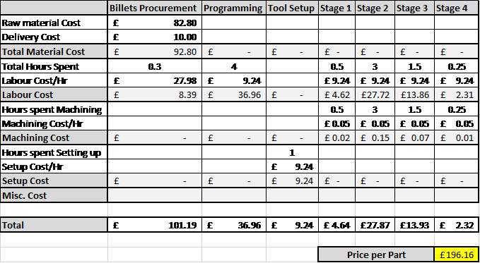
Table 9 Prototype Upright Synthetic Cost Analysis
The material cost was taken from the £82.80 quoted by the supplier with the addition of half the £20 delivery cost for both billets. The labour, programming and setup cost was based on the January 2017 average U.K. machinists hourly salary of £9.24 (31). Labour was assumed for all hours processed in each Stage and setup cost was based on the time required per part to prepare machinery and ensure the part was correctly seated in the jig. Each part required 4 hours programming in Edgecam CAD CAM software to check the load paths and complete the setup, this was the most labour intensive stage. The machining cost was the total price of all consumables divided by the total life of the consumable to provide a cost per hour. In addition to this, an estimation of energy usage was also factored into this category.
The total price per part was estimated to be £196.16, or £392.32 for the manufacture of both components. Material procurement was the most expensive stage of manufacture with the initial roughing stage 1 and lathe stage 4 being the least expensive.
Removing the largest investment of material procurement resulted in much cheaper wishbones, leaving more budget for the upright’s costly manufacture. Previous wishbone bracket removal, jig creation, welding and assembly of the wishbones totalled approximately 3 man-hours of technician’s time, as much of this process was aided or carried out by the author. Six hours at the £9.24/hour as above yields a total cost of £27.72, or £13.86 per wishbone.
8 EVALUATION
To conclude and judge the success of the project, the optimised suspension was compared to the previous year’s system. Additionally, the author carried out a critical review of the project process and compared the project outcomes to the original aims and objectives.
8.1 IMPROVEMENT ON PREVIOUS YEARS
Table 10 displays key optimisation points between the current and previous designs. Material cost included is simply the raw material cost per part, calculated from mass and the London metal exchange price for the untreated aluminium (32).
| Criteria | Upright | Wishbones | ||||
| 2015 POLIS | 2016 POLIS | Difference | 2015 POLIS | 2016 POLIS | Difference | |
| Mass | 1557g | 656g | -901g | 484g | 385g | -99g |
| Material | 6061 | 6082-T6 | N/A | Steel | 6082-T6 | N/A |
| Process | Machining | Casting | N/A | Forming | Casting | N/A |
| Volume | 580.8cm3 | 242.1cm3 | -338.7cm3 | 61.6cm3 | 142.1cm3 | +80.5cm3 |
| Material Cost | $2.60 | $1.10 | -$1.50 | $0.81 | $0.64 | -$0.17 |
The above benefits in Table 10 highlight some additional sustainability improvements as by-products. For example, less waste material from casting instead of machining not only reduces material cost but also reduces emissions during production and refinement of the material. In addition to this, the smaller cast part would require less metal to be heated and cooled and therefore reduce energy consumption, hence emissions during manufacture.
The use of multiple FEA solvers and a comparison between them, Figure 27, had not been carried out in previous years, allowing for a direct comparison under the same conditions. This resulted in more reliable FEA results because the solvers not only highlighted the same areas of stress concentration but also yielded similar results. Dynamic loading conditions were also considered and analysed with FEA which was a precaution also unexplored in previous years.
Furthermore, for the 2016 POLIS suspension, more economically viable manufacturing processes had been chosen and researched in depth to gain a more comprehensive breakdown of theoretical mass production costs than before.
8.2 CONCLUSION
In conclusion, the suspension system for POLIS vehicle has been designed to offer a notable improvement against previous years, both in terms of manufacturing time and cost but also in terms of function. It has also been identified that the suspension system is suitably designed for its purpose and the POLIS vehicle would be well placed in the automotive market.
The aim to design, develop and manufacture the suspension components have been achieved in great detail through extensive research and use of CAE and advanced design techniques. The purpose of this report was also to document this process and the stages involved in reaching the final designs.
Manufacture and integration of the upright and wishbones into the current prototype vehicle with no fitment issues and sufficient strength validate their design. The FEA performed on the production intent models cannot be solely replied upon due to the limitations of the testing and physical testing of exact mock-ups from production tooling would need to be carried out to validate this. The boundary and loading conditions utilised in the FEA
The POLIS vehicle upright and wishbones can be produced for £4.81 and £3.37, respectively, with tooling cost spread across the component piece price. 12,000 full systems will be produced annually to maintain the pace of the overall vehicle production and place it well within the competitive market. The vehicle will also meet the European ELV directives and ISO standard surrounding sustainability and safety, this was achieved by having a critical awareness of LCA throughout the project. However, the size and layout of the vehicle will cause a lot of safety concerns that will require independent crash and safety testing.
8.3 AREAS FOR FURTHER STUDY
A potential area of further study directly highlighted by this project is into the manufacture and application of biodegradable materials that can replicate the positive properties of common materials at reasonable cost. The author strongly recommends continuing to research the field of biodegradable city vehicles to make the project more commercially viable when suitable materials and their associated production become cheaper.
Further study should be done on the suspension of the POLIS vehicle, the limited track width and ever-changing city environment is an extremely fast moving area of study and there is potential to research novel solutions. Additional steering lock to cope with tight inner city corners could be considered as well as autonomous modular vehicle designs, i.e. combining multiple POLIS vehicles together for long journeys for more efficient travel. Studying the effects of bearing efficiency and brake or suspension stoke regeneration on the drain on the battery are promising areas of research that could assist in reducing the POLIS vehicle’s emissions across the full life cycle if this was to become the focus of the project in the future.
REFERENCES
Primary Sources
2. Audi-AG. Life Cycle Assessment – Audi looks one step ahead. In: AG A, editor.: Climate Partner; 2011.
3. UN. World urbanization prospects : the 2007 revision. New York: United Nations; 2007.
4. UN. The Components of Urban Growth in Developing Countries. 2001 Edition ed. New York: United Nations; 2001.
5. Pugh S. Total design. 1990 ed: Addison-Wesley; 1990. 256 p.
6. Fiat-Group. Fiat Group Environmental Report. Turin: Fiat S.p.A. Government Affairs and International Relations.; 2006.
7. 2013 Sustainability Report [press release]. fcagroup.com: Graf Art2013.
8. Fiat-Group. Roadmap of propulsion-vehicle systems. In: Fiat Group M-MaPB, editor. pg 55. 1 ed. Fiat Group Sustainability Report 2013: Fiat Group; 2013.
9. Halderman JD. Automotive steering, suspension, and alignment. 5th ed. Boston, [Mass.] ; London: Prentice Hall; 2010.
10. Sloman L. Car sick : solutions for our car-addicted culture. Totnes: Green; 2006.
11. Mitchell WJ, Borroni-Bird C, Burns LD. Reinventing the automobile personal urban mobility for the 21st century. Cambridge, Mass. ; London: MIT Press; 2010. Available from: https://www.dawsonera.com/Shibboleth.sso/Login?entityID=https%3A%2F%2Fidp.herts.ac.uk%2Fshibboleth&target=https://www.dawsonera.com/depp/shibboleth/ShibbolethLogin.html?dest=http%3A%2F%2Fwww.dawsonera.com%2Fdepp%2Freader%2Fprotected%2Fexternal%2FAbstractView%2FS9780262288552.
12. Scoltock J. Small is beautiful: by rethinking the packaging for its tiny city car, the iQ, Toyota has devised a plan for making its future B-segment vehicles smaller, yet more spacious too. Automotive engineer. 2008;33(11).
14. Standards B. BS 7373-1: Guide to the preparation of specifications. . Guide to the preparation of specifications Bsigroup.com: British Standards Institute; 2001.
15. Haritos G. Design Methodologies In: Haritos G, editor. Vehicle Engineering Design: University of Hertfordshire; 2016.
16. Lexus. Lexus IS 200 Repair Manual. 1 ed: Toyota Motor Corperation; 1999.
19. Denford. VR CNC Milling 5. In: Denford, editor. Software. Denford Software Catalogue: Denford; 2017. p. 44-5.
21. Feld WM, Ebooks Corporation. Lean Manufacturing : Tools, Techniques, and How to Use Them. Hoboken: CRC Press; 2000. Available from: https://login.openathens.net/saml/1/sso/herts.ac.uk/c/ukfed?target=http%3A%2F%2Febookcentral.proquest.com%2Flib%2Fherts%2Fdetail.action%3FdocID%3D263790&shire=https%3A%2F%2Fsp.eblib.com%2FShibboleth.sso%2FSAML%2FPOST&providerId=https%3A%2F%2Fsp.eblib.com%2Fshibboleth.
22. Wilwood. GP 200 BILLET CALIPER. Camarillo, CA: Wilwood Disc Brakes; 2015.
23. Chasib O. Design for Manufacturing2014 April 2017:[13 p.]. Available from: https://www.slideshare.net/OmerChasib/dfma-design-for-manufacturing-and-assamply?from_action=save.
24. Gillespie TD, Society of Automotive Engineers. Fundamentals of vehicle dynamics: SAE; 1992.
25. MDOT, editor Introduction to the International Roughness Index. Bituminous Smoothness Training Workshop; 2007; Minnesota: Minneota Department of Transportation.
27. Yahr GT. Fatigue Design Curves for 6061-T6 Aluminum. 1993 American Society of Mechanical Engineers (ASME) Pressure Vessel and Piping Conference; July 1993; Denver, CO: Oak Ridge National Lab. (ORNL), Oak Ridge, TN (United States); 1993.
29. Pattnaik S. DESIGN FAILURE MODES AND EFFECTS ANALYSIS (DFMEA) OF AN ALL-TERRAIN VEHICLE. IJRET: International Journal of Research in Engineering and Technology. 2015;4(6):339-435.
30. Pontes J. EV-sales [Internet]. ev-sales.blogspot.co.uk: Jose Pontes. 2014 30th January 2014. [cited 2017]. Available from: http://ev-sales.blogspot.co.uk/2014/01/world-top-20-december-2013-special.html.
Internet Sources
1. Greenpeace. Cars and Climate Change Q+A Greenpeace.org: Greenpeace; 2008 [updated 17 March, 2008. What is the share of cars in climate change?]. Available from: http://www.greenpeace.org/international/en/campaigns/climate-change/cars/questions-answers/.
13. Aluminium-Association. Automotive Quick Read: The Aluminium Association; 2017 [Available from: http://www.aluminum.org/product-markets/automotive.
17. Smart. smart fortwo coupe: Daimler AG; 2017 [updated March 2017. Available from: http://uk.smart.com/uk/en/index/smart-fortwo-453.html.
18. Longhurst C. Car Bibles [Internet]. Longhurst C, editor. carbibles.com: Self. 2017. [cited 2017]. Available from: http://www.carbibles.com/steering_bible.html.
20. Edgecam. Edgecam Products Edgecam.com: Hexagon; 2017 [updated 2017. Edgecam is a market leading computer aided manufacturing (CAM) system for NC part programming.]. Available from: http://www.edgecam.com/products.
26. Demontweeks. Nankang AS-1 Performance Tyre [Automotive Sales Website]. http://www.demon-tweeks.co.uk: Demon-Tweeks; 2017 [updated 2017. Available from: http://www.demon-tweeks.co.uk/performance/tyres/nankang-as-1-performance-tyre.
28. Matweb. Overview of materials for Medium Carbon Steel Matweb.com: Matweb.com material property data; 2017 [updated 2017. Available from: http://www.matweb.com/search/DataSheet.aspx?MatGUID=098700ed63b24b14bd3bfdbec937489f.
31. Payscale.com. Machinist Salary (United Kingdom) 2017 [updated 18th Jan 2017. Available from: http://www.payscale.com/research/UK/Job=Machinist/Hourly_Rate.
32. LME. LME Aluminium Alloy: Stocks and Prices lme.com: London Metal Exchange; 2017 [updated 4 April 2017. Available from: http://www.lme.com/metals/non-ferrous/aluminium-alloy/#tab2.
BIBLIOGRAPHY
[The heading above is set to Heading 1 paragraph style but with the automatic number deleted. The Bibliography section does not normally have a number. Paragraph styles need to be used consistently so that the automatically generated table of contents works correctly]
[ENTER YOUR BIBLIOGRAPHY HERE – Books and other reading matter not specifically referred to in the text but considered useful reading matter should be listed in the Bibliography. The format of the items in the bibliography should be the same as for refere
APPENDIX A
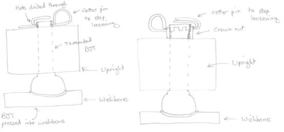
Figure A – 1 Sketch of Ball-joint Fixing Concepts 1
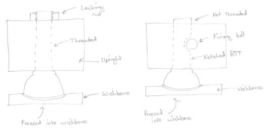
Figure A – 2 Sketch of Ball-joint Fixing Concepts 2
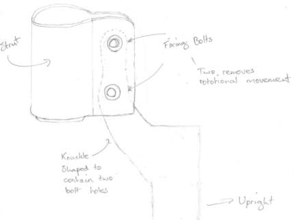
Figure A – 3 Sketch of Strut Mounting Bracket Concept
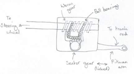
Figure A – 4 Sketch of Recirculating Ball Steering Box Concept
APPENDIX B
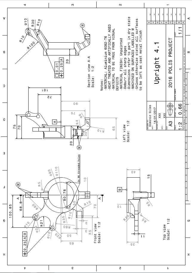
Figure B – 1 Production Intent Upright Technical Drawing
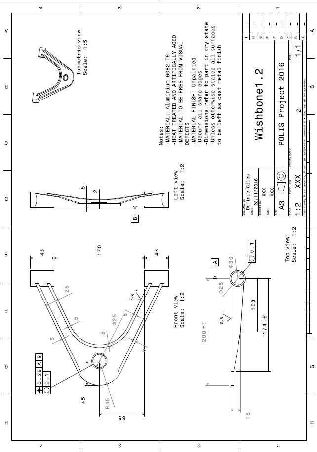
Figure B – 2 Production Intent Wishbone Technical Drawing
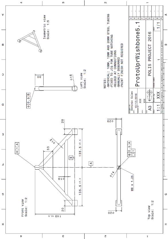
Figure B – 3 Prototype Upper Wishbone Technical Drawing
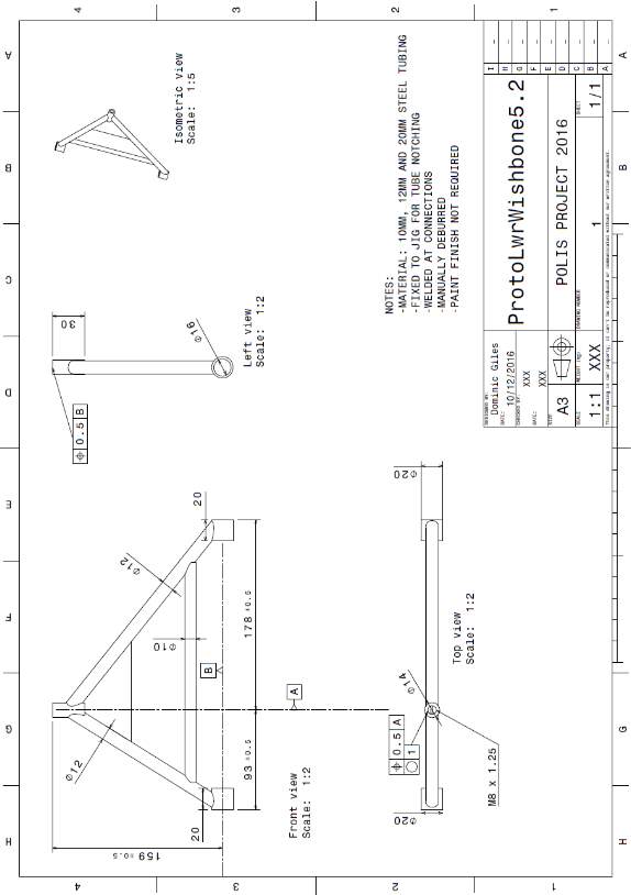
Figure B – 4 Prototype Lower Wishbone Technical Drawing
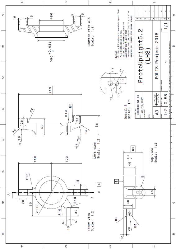
Figure B – 5 Prototype Upright Technical Drawing
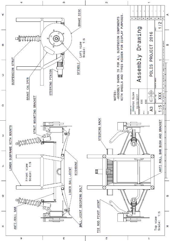
Figure B – 6 Assembly Technical Drawing Sheet 1
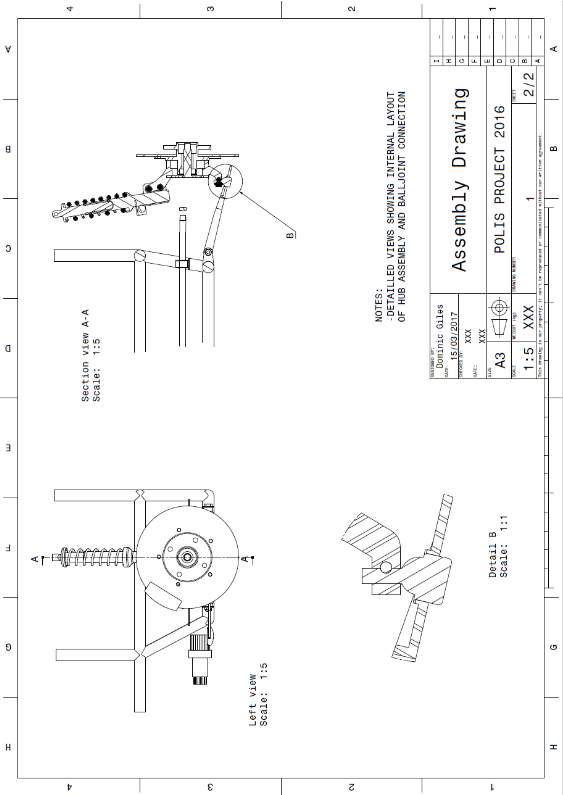
Figure B – 7 Assembly Technical Drawing Sheet 2
APPENDIX C
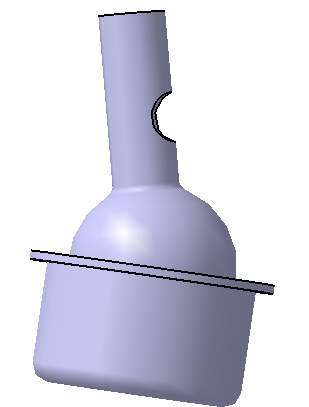
Figure C – 1 3D Model of Lower Ball-Joint in Inclined State
For the production intent model the ball-joint is secured with a notch and bolt.
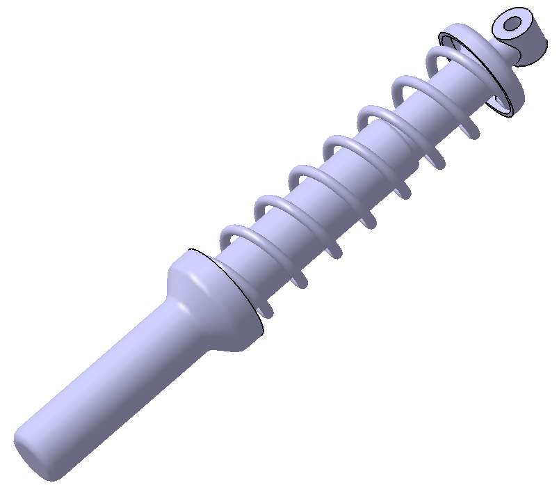
Figure C – 2 3D Model of Suspension Strut
The previous year’s production intent suspension strut was adapted to purpose, the specifications were checked on the manufacturer website to confirm the spring and damper size would suit a MacPherson strut application. The bottom body of the strut was then extended for a secure connection to the upright.
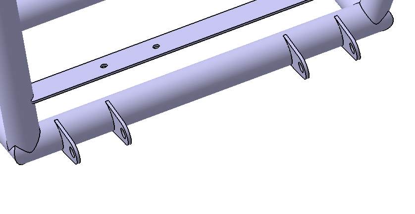
Figure C – 3 3D Model of Modified Brackets
The production intent wishbone mounting brackets were adapted from the main frame that remained unchanged. This ensured the geometry was correct and matched the simulation on Lotus Shark.
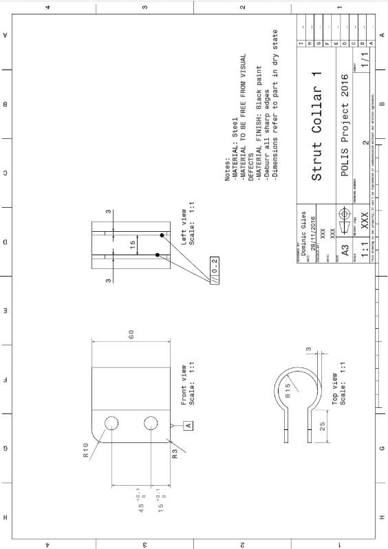
Figure C – 4 Strut Collar Technical Drawing
APPENDIX D
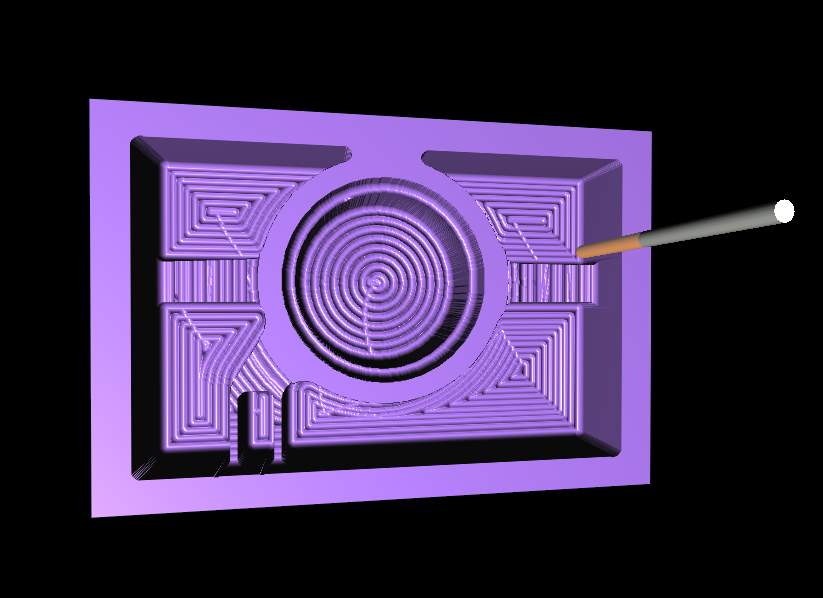
Figure D – 1 CAE Machined Upright
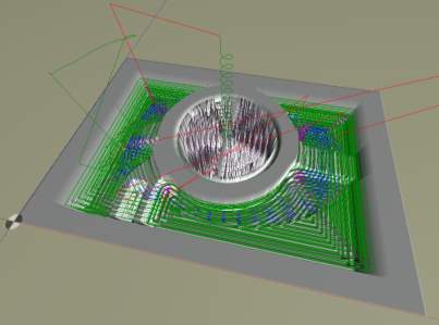
Figure D – 2 Upright Machining Tool Path Simulation
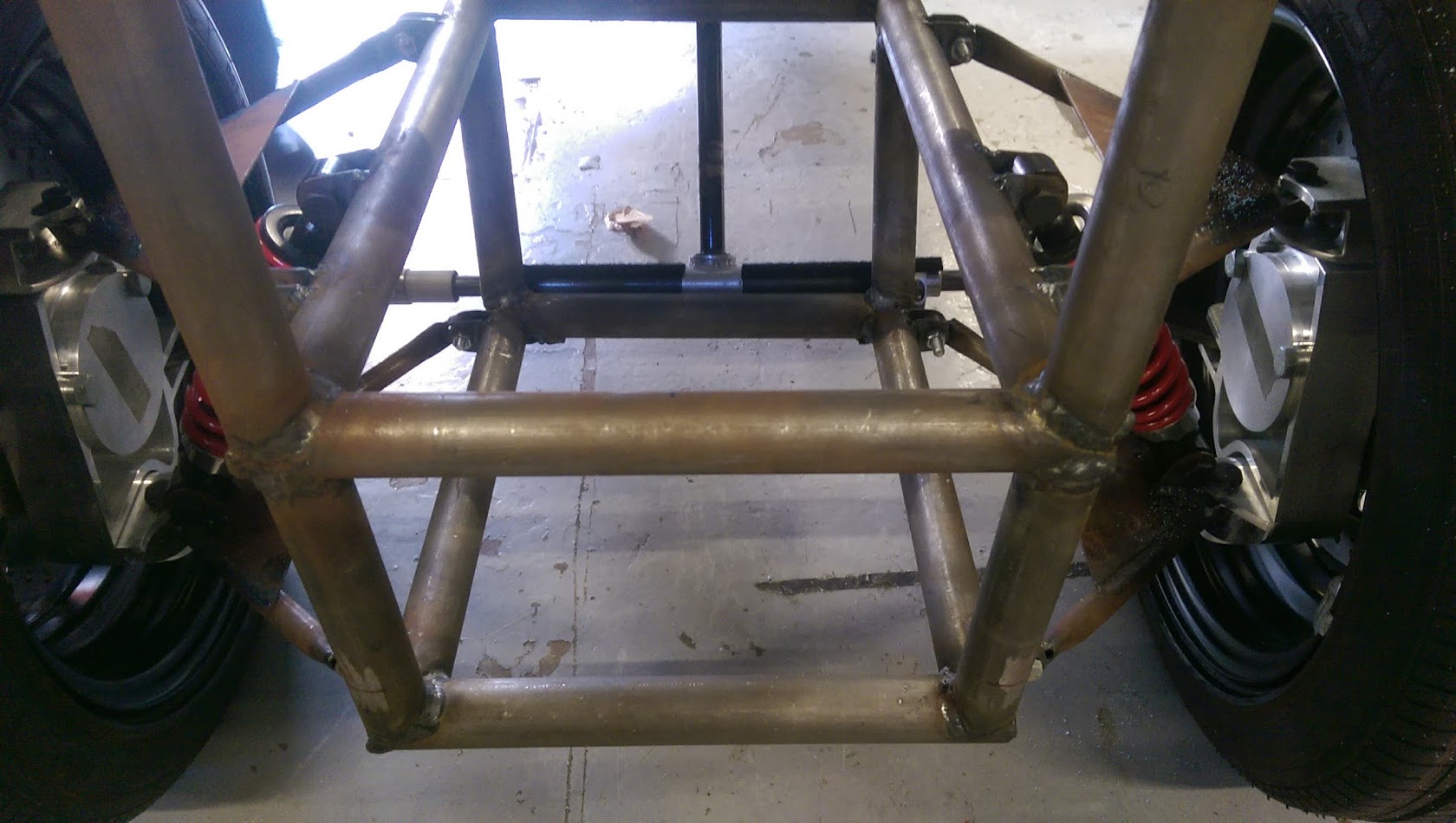
Figure D – 3 2015 Old POLIS Front Suspension
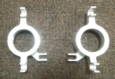
Figure D – 4 Finished Prototype Uprights
Please note: Unfortunately due to technical officer availability the prototype wishbones and full assembly pictures were acquired in time for report submission. The parts are currently attached to the vehicle and these pictures will be available as separate slides during project viva.
APPENDIX E
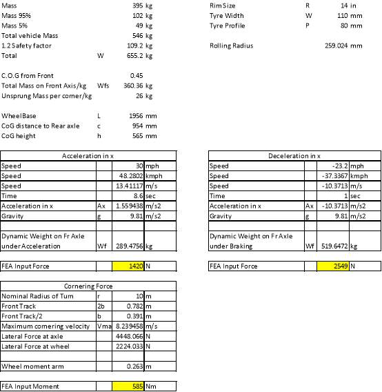
Figure E – 1 Load Calculations for Production Intent FEA Load Cases
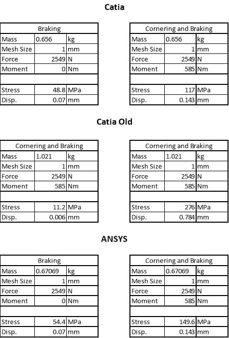
Figure E – 2 Raw Results from FEA
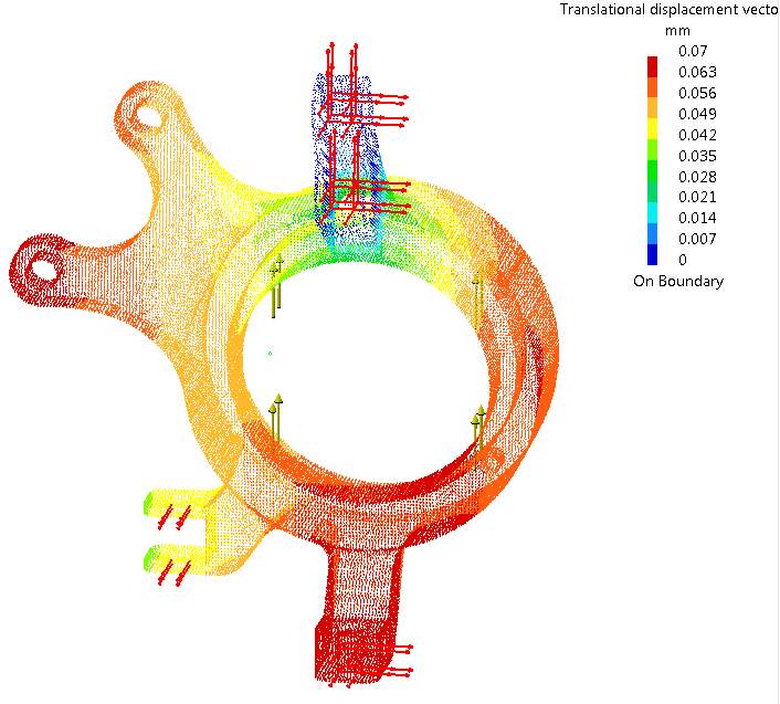
Figure E – 3 Catia Displacement of Upright under Braking
Braking displacement is extremely even and low throughout the upright.
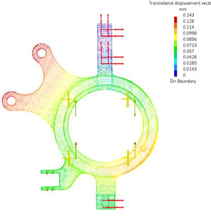
Figure E – 4 Catia Displacement of Upright under Cornering and Braking
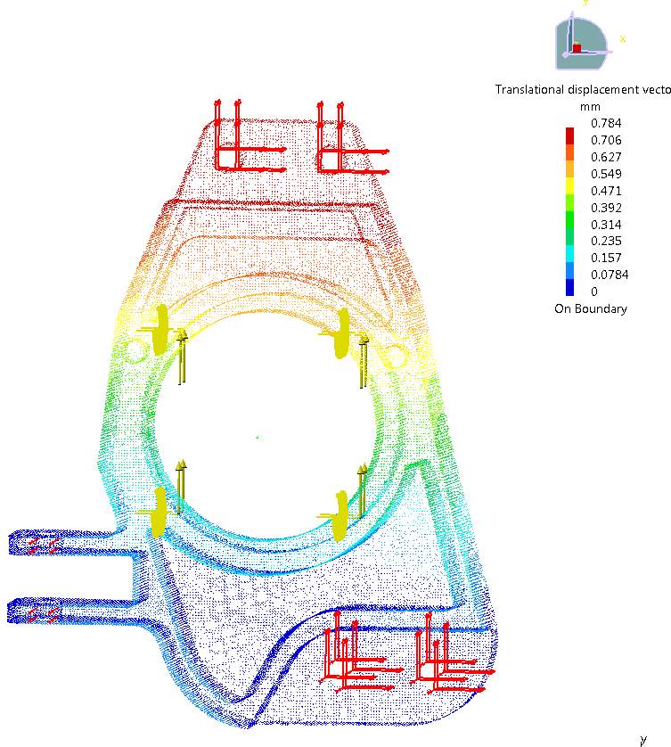
Figure E – 5 Catia Displacement of Old Upright under Cornering and Braking
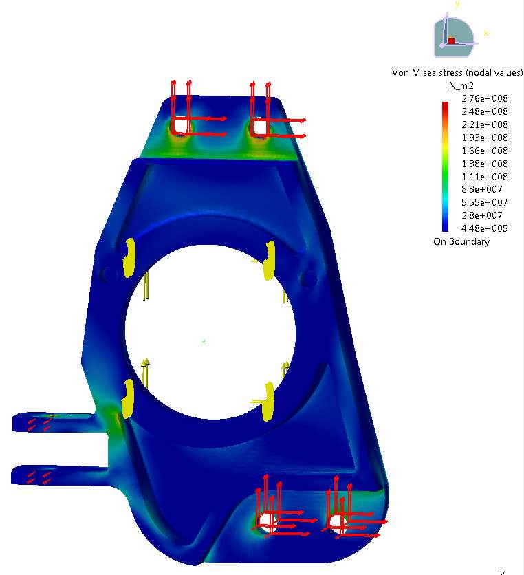
Figure E – 6 Catia von Mises Stress of Old Upright under Cornering and Braking
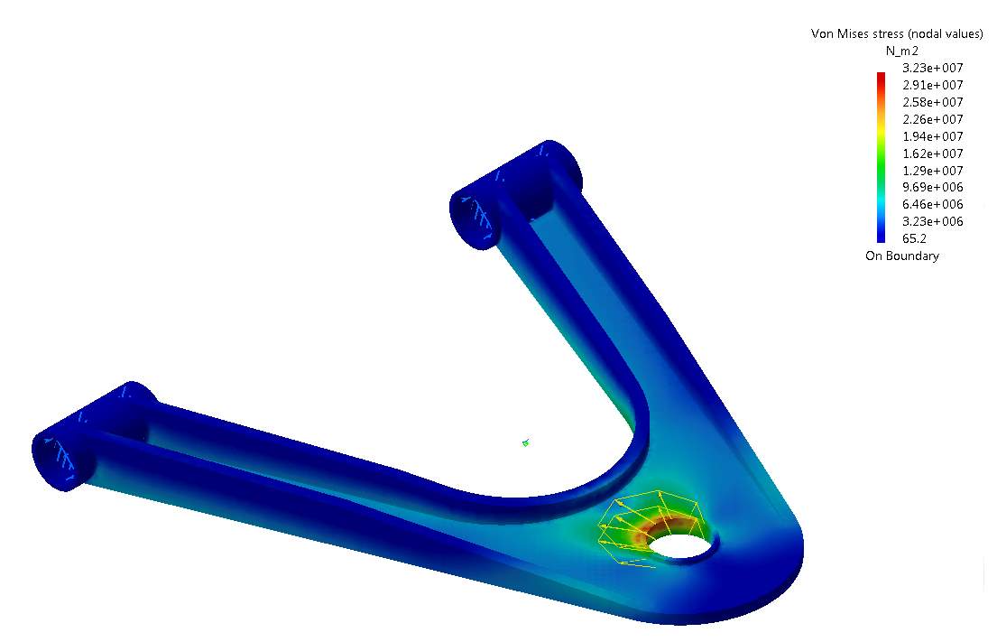
Figure E – 7 Catia von Mises Stress of Production Intent Wishbone
APPENDIX F
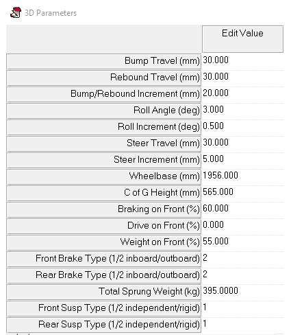
Figure F – 1 Lotus Shark Suspension Analysis 3D Parameters
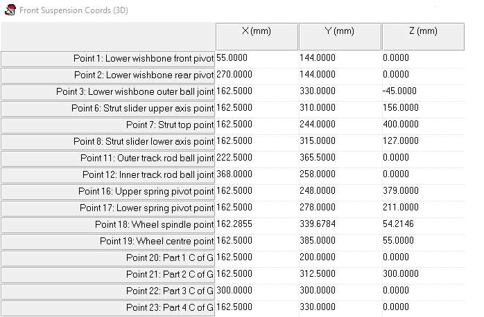
Figure F – 2 Lotus Shark Suspension Analysis Suspension Co-ordinates

Figure F – 3 Lotus Shark Suspension Analysis Top View Static and Full Lock
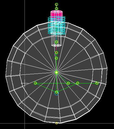
Figure F – 4 Lotus Shark Suspension Analysis Static Side View
APPENDIX G
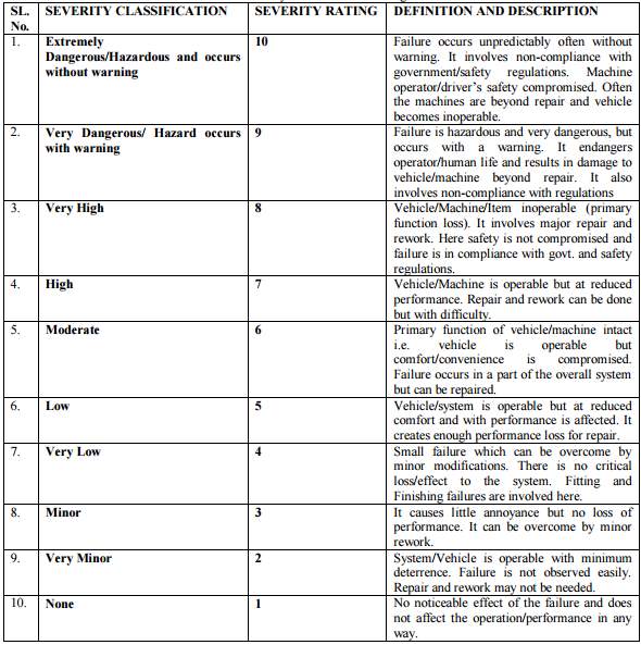
Figure G – 1 FMEA Severity Criteria and Rating Definition
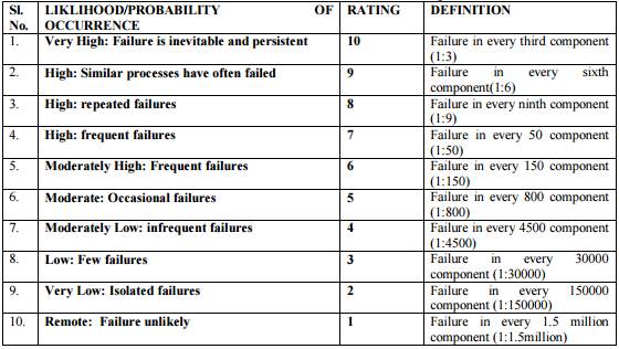
Figure G – 2 FMEA Likelihood of Occurrence Criteria and Rating Definition
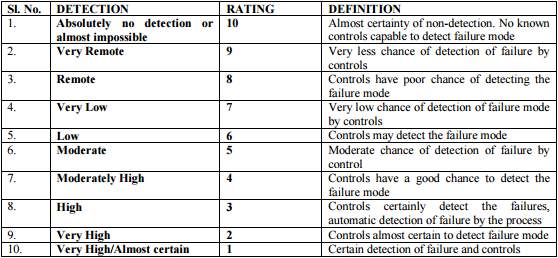
Figure G – 3 FMEA Likelihood of Detection Criteria and Rating Definition
Cite This Work
To export a reference to this article please select a referencing stye below:
Related Services
View allRelated Content
All TagsContent relating to: "Energy"
Energy regards the power derived from a fuel source such as electricity or gas that can do work such as provide light or heat. Energy sources can be non-renewable such as fossil fuels or nuclear, or renewable such as solar, wind, hydro or geothermal. Renewable energies are also known as green energy with reference to the environmental benefits they provide.
Related Articles
DMCA / Removal Request
If you are the original writer of this dissertation and no longer wish to have your work published on the UKDiss.com website then please:


