Utilizing the Hygrothermal Performance of Sheep Wool, Re-cycled Newspaper and Wood Fibreboard Insulation
Info: 17354 words (69 pages) Dissertation
Published: 11th Dec 2019
Tagged: Environmental Studies
Benefits of utilizing the hygrothermal performance of sheeps wool, Re-cycled Newspaper and Wood Fibreboard insulation, in reducing the risk of potential moisture build-up in retrofitting external walls
We spend most of our time as human beings in man-made environments. We work, exercise, sleep and relax within the buildings that we design and as a direct result, the environments that we create for these buildings will have a huge effect on the quality and comfort of the day-to-day lives of many people.
This document looks at the possibility of using three forms of bio-based materials (sheep’s wool, recycled newspaper and wood fibre) to insulate our domestic homes, highlighting the differences between these environmentally friendly alternatives, to the more common fibreglass, mineral wool and polyurethane foam.
By utilizing the hygrothermal performance of the biomaterials, these alternatives also have the added benefit of having a stabilizing effect on the relative humidity of internal spaces. This document will look at how these materials behave in a simple, breathable wall construction and whether moisture within the materials will build up over time to cause potential problems like mould and a reduction in thermal performance.
Abstract
Acknowledgements
Contents
1.0 – List of Figures
2.0 – List of Tables
3.0 – Definitions
4.0 – List of Symbols
5.0 – Introduction
5.1 – Hypothesis
5.2 – Steps of Research
6.0 – Review of Literature
6.1 – Background
6.1.1 – Current Energy Situation
6.1.2 – Benefits of Insulation
6.1.3 – Wall Designs
6.1.3.3 – Timber Frame
6.1.3.1 – Solid
6.1.3.2 – Cavity
6.1.4 – Problems Arising Post Retro Fit
6.1.5 – Vapour Barrier
6.1.6 – Man-Made Insulation
6.1.7 – Bio-Based Insulation
6.2 – Material Information
6.2.1 – Sheep Wool (Black Mountain)
6.2.2 – Cellulose (Nesocel)
6.2.3 – Wood Fibreboard (STEICO)
7.0 – Laboratory Experimentation
7.1 – Methodology
7.1.1 – Bulk Density
7.1.2 – Moisture Storage Functions
7.1.3 – Thermal Conductivity
7.2 – Results
7.2.1 – Bulk Density
7.2.2 – Moisture Storage Functions
7.2.3 – Thermal Conductivity
8.0 – WUFI Simulation
8.1 – Methodology
8.2 – Simulation Settings
8.2.1 – External Climate
8.2.2 – Internal Climate
8.2.3 – Wall Build-Ups
8.2.3 – Material Properties for Bio-Materials
8.3 – Results
8.3.1 – Relative Humidity Accumulation
8.3.2 – Thermal Performance Impact
9.0 – Analysis
9.1 – Critical Monitoring Location Justification
9.2 – Sensitivity to Variations in Material Properties
9.3 – Mass Spectrometry Imaging
10.0 – Discussion
10.1 – Reliability
10.1.1 – Laboratory experimentation
10.1.2 – Hygrothermal Simulation
10.2 – Limitations to the findings
11.0 – Conclusion
12.0 – Reflection and Future Work
References
Appendix A – WUFI Material Database
Appendix B – Dry and Moisture Dependent Thermal Conductivity
Figure 1 – Dissertation research flow chart
Figure 2 – 2015 Energy consumption, excluding transport (BEIS, 2016)
Figure 3 – Energy losses through the external envelope of an average home (The Green Age, 2016)
Figure 4 – Common practice timber frame design in the 1970’s
Figure 5 – Cavity wall construction and its moisture protective measures
Figure 6 – Sheeps Wool used throughout this research
Figure 7 – Cellulose used throughout this research
Figure 8 – Wood Fibreboard used throughout this research
Figure 9 – DVS Intrinsic apparatus schematic (Surface Measurement Systems Ltd, 2015)
Figure 10 –sheeps wool isotherms for sorption and desorption
Figure 11 – Cellulose isotherms for sorption and desorption
Figure 12 – Wood Fibreboard isotherms for sorption and desorption
Figure 13 – Thermal conductivity, temperature and moisture dependency
Figure 14 – Thermal conductivity comparisons
Figure 15 – Annual average temperature data, Bristol, United Kingdom
Figure 16 – Annual driving rain data, Bristol, United Kingdom
Figure 17 – One dimensional wall build-ups of considered cases, including monitoring location.
Figure 18 – Critical relative humidity, with various thicknesses of sheeps wool
Figure 19 – Critical relative humidity, with various thicknesses of cellulose
Figure 20 – Critical relative humidity, with various thicknesses of wood fibreboard
Figure 21 – Comparison of the critical relative humidities between materials
Figure 22 – Dry U-values compared with actual U-Values
Figure 23 – Relative humidity profiles for WUFI simulations for all cases
Figure 24 – Upper and lower bound sensitivity checks
Figure 25 – sheeps wool taken from mass spectrometry imaging
Figure 26 – Cellulose taken from mass spectrometry imaging
Figure 27 – Wood Fibreboard taken from mass spectrometry imaging
Table 1 – Basic material properties
Table 2 – Measured bulk densities
Table 3 – Simulated scenarios
Table 4 – Additional input data for the WUFI Simulation
Table 5 – Material properties for the hygrothermal simulation
Table 6 – Approximated water absorption data
Table 7 – Upper and lower bound sensitivity values
Table A-1 – Additional materials used from the WUFI material database
Table B-1 – U-Value calculations with corresponding thermal conductivity values
Hygrothermal –
Hygroscopic
Vapour Barrier
Isotherm
Hysteresis
Heat Resistance
External Sd-Value
Short-Wave Reflectivity
Adhering Fraction of Rain
Internal environments are getting warmer and more airtight due to more rigorous building regulations and advances in materials and technologies. Because of this advancement there is an added risk of mould generation, if the designs of new buildings or retrofits are not holistic. This will occur if the ventilation system is not sufficient and if moisture within the internal environment is not able to escape through the external envelope, because of the vapour barrier.
This research looks at the effect of using hygroscopic, bio-based insulating materials as a replacement for the vapour barrier in the external walls of timber framed design, in the Bath and Bristol area of the United Kingdom. The specific materials that have been considered in this research are sheeps wool, cellulose and wood fibreboard.
The aims were to justify that hygroscopic materials are valid alternitives for vapour control means in construction, along with analysing their effect on a walls thermal performance and its impact on the distribution of moisture throughout the elements of the wall.
By replacing the vapour barrier in timber framed design with a hygroscopic alternative the thermal performance can be improved and an additional buffer to the internal relative humidity can be provided, improving occupancy health and reducing the risk of mould growth, without detrimentaly effecting the moisture profiles within the wall.
To answer the hypothesis the steps set out inFigure 1 were followed. A review of the literature has been critically analysed for its relevance to the hypothesis, ensuring the information reported is concise. If further information is required then all sources used throughout have been included at the back of this report.
Physical experimentation was performed to determine the material properties that a hygrothermal model is most sensitive to. This was done so that the computer software can run a more accurate simulation. The two material properties that were determined via experimentation was the moisture storage isotherm and the materials thermal conductivity, dependent on moisture content. As naturally occurring materials are the focus of this research, simple measurements of the bulk density were also measured in order to determine their variation from the manufacturers reported values.
After the WUFI simulation was performed the results were interpreted and analysed to determine whether the wall construction would cause locations of high relative humidity, resulting in potential mould and bacteria growth. This is reported during Sections 9 – 11. The possible areas for advancing this research and the improvements that could be made, have been outlined in Section 12 of the report.
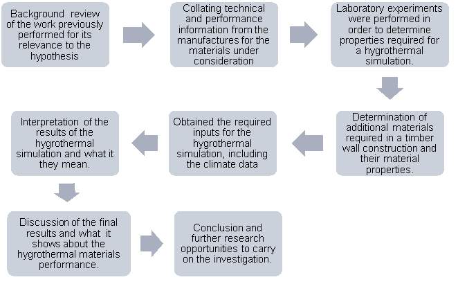
Figure 1 – Dissertation research flow chart
6.1.1 – Current Energy Situation
Globally it is widely accepted that the consumption of energy and consequently the production of carbon dioxide is significantly above a safe limit. In 2015, the global amount of carbon dioxide emitted because of fossil fuels and cement production was the highest in history at 36.2 GtCO2 (Le Quéré, et al., 2016). This is not a surprise as there has been an upward trend since the carbon budget started publishing figures and it is predicted to increase further in the years to come. The biggest emitters of carbon dioxide are the United States of America and China and in 2015 the United Kingdom was 15th (Boden, et al., 2015).
In a bid to reduce the United Kingdom’s production of carbon dioxide, the government committed to reduce its carbon account to less than 80% of the 1990 baseline by 2050 (Climate Change Act, 2008). This incentive was set 9 years ago, since then a reduction of 11.0% in the total energy consumption has been observed, which in turn equates to a 6.7% reduction from the energy consumption in 1990 (BEIS, 2016).
Albeit, the general trend of energy consumption is downwards, this is mainly caused by the technological advances in the industrial sector and the domestic sector has not contributed to the reduction in energy consumption. Instead energy demand in the domestic sector is 3.2% higher than the 1990 baseline (BEIS, 2016).
In 2014, the United Kingdom had a housing stock of 28 million dwellings (Department for Communities and Local Government, 2016) and the average annual energy consumption was 19,800 kWh (Ofgem, 2011), meaning there is a significant potential for reduction within the sector. As the domestic sector is now the 2nd biggest contributor to the UK’s energy bill, the government is likely to focus more on the efficiencies of the housing stock in the future, if it is to adhere to its carbon promise. It is likely that the government’s focus will be on refurbishments, as it is predicted that 85% of UK’s existing housing stock will still be in use in the year 2050 (Safeguard Europe Limited , 2016).
6.1.2 – Benefits of Insulation
By introducing insulation to the external envelope of a building, the amount of energy lost can be directly impacted, therefore reducing the energy demands of the building. Figure 2 shows the proportion of energy used in the UK to heat internal spaces compared to other energy uses and if transport is excluded from this analysis then heating spaces is easily the largest contributor to the UK energy bill, all of which could be reduced by adding additional insulation.
Although it is clear that adding insulation is beneficial for the wider community and would be a small part of the solution to global warming. Convincing individuals to pay the upfront cost of additional insulation, requires an individual cost-benefit analysis based on your climate and comfort requirements. This is the reason that it would not be possible to reduce the energy demand for heating to zero. The additional mark-up cost on a new house built to an energy efficient standard is between 40 % and 50 % (Element Energy and Davis Langdon, 2012). This cost is an extreme case for a level 6, trailblazing building in terms of energy efficiencies, in accordance with the Code for Sustainable Homes (Department for Communities and Local Government, 2010). It is more likely that individuals will settle for a building of level 3 or 4, in terms of this code, where the extra cost is between 1.5% for level 3 and 5.8% for level 4, higher than a building built to the standard building regulations.
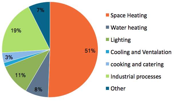
Figure 2 – 2015 Energy consumption, excluding transport (BEIS, 2016)
At the price increase of a level 3 or 4 building, individuals are likely to justify the additional up front cost to reap the benefits of a reduced energy bill for future years or to simply have a higher level of comfort, this is currently becoming more common as a result of the governments green deal (2012). Along with the reduction in energy bills, studies have also shown that insulating buildings improves the health of the tenants especially for children and over-65’s, resulting in fewer days off from work and fewer visits to their local GP (Chapman, et al., 2009).
The impact that insulation has on energy consumption however is dependent on the location that it is installed. Figure 3 is a widely-accepted breakdown which highlights where heat energy is lost in a standard detached dwelling. Along with this the building type also has its role in determining the effectiveness of envelope insulation. S. Al-Homoud (2005) summarised that dwellings, like middle terrace houses, lose a lower amount of energy compared to detached dwellings. This is because their sidewalls are connected to another dwelling and therefore there is no temperature gradient driving heat loss. Although the benefit varies from house to house this research has focused on externally facing, timber wall constructions, however the theory and experimental results can be repeated to model many different house types that are either completely or partially insulated with bio-based insulation.
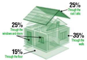
Figure 3 – Energy losses through the external envelope of an average home (The Green Age, 2016)
As it is predicted that 85% of our housing stock for 2050 has already been built, then it seems logical that research should be focused on improving older wall constructions, in order to reach or better the current building regulations. A significant amount of research has already been completed with regards to this area and has resulted in the number of un-insulated homes to fall from 96.2% in 1976 to 27% in 2016 (BEIS), however there is still potential to improve the situation further.
This research is only going to be looking at a typical timber wall construction, however there is potential in expanding this research into looking at the effect of installing hygroscopic materials to other wall constructions. For this reason a review of the three main wall constructions has been reported below.
Timber construction has been attractive for housing developers, due to its ease of repeatability and its speed of construction, with potential benefits of reducing construction time and therefore increasing profits (Välikangas, 2002). In the past however, timber construction has been known for its problems associated with wet and dry rot. This was brought to the publics attention in a documentary by World in Action (1983) and made timber dwellings unpopular for the following 15 years. Since the turn of the 21st century there has been a resurgence in timber construction, caused by a better understanding in the behaviour of timber walls. This has caused the market share of timber new builds to increase massively (reference).
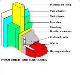
Figure 4 – Common practice timber frame design in the 1970’s
Timber construction typically has an outer layer of cladding, along with an air cavity to protect the structure from moisture and driving rain. This is followed by a breathable membrane, the timber frame and the insulation, which would have been protected from the internal environment by a vapour barrier. The internal layer would have been finished with a plaster board lining, protecting the vapour barrier (Harrison, et al., 2004). As this report is focusing timber buildings then the wall constructions shown in Figure 4 will form the basis of this research.
Solid wall construction was a popular design pre-1920 and it was usually built out of brick or stone. They consist of a single leaf, which means that they have poor thermal performance and little to no protection against moisture ingress. A typical U-value for an uninsulated solid brick wall is 2.97 W/m2K (Milne, 2015), which is very poor and is higher than most glazing systems on the market today.
Cavity Wall construction became the most common wall type during the 20th century (Lynch, 2015). Driving rain is stopped by the external leaf, while it also acts as a buffer to fluctuations in the external relative humidity. Due to the porosity of brick, the outer layer can never be fully effective and water in both liquid and gaseous phases can penetrate to the air cavity. This flow of moisture is therefore controlled by keeping the air cavity ventilated, meaning any moisture which isn’t blocked by the outer leaf is removed and drained away, ensuring the inner leaf is kept dry as shown in Figure 5. This process means that the air cavity between the leafs is a vital component of the walls moisture control.
The thermal performance of an uninsulated wall of this type is better than a single leaf construction, however it still does not meet any modern building regulations with a typical U-value of 1.37 W/m2K (Milne, 2015). Since the 1970 energy crisis there has been a bigger push for home owners to add additional insulation to their external walls (Lynch, 2015) to improve the U-value. Polystyrene was typically the material of choice, as it was the easiest to install. The benefit of this was that the additional insulation to the cavity did not increase the thickness of the actual wall and if polystyrene was chosen then it could be installed with minimal impact to the dwelling, however it did lead to problems which have been outlined in Section 6.1.4.
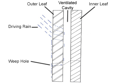
Figure 5 – Cavity wall construction and its moisture protective measures
6.1.4 – Problems Arising Post Retro Fit
The distribution of moisture across a wall construction can be disturbed and altered by any modification to wall design, like adding additional insulation or vapour controls. This disruption in the dynamic equilibrium means that there is a potential for condensation to occur, something which this research is considering as this encourags mould to grow within the wall. This causes detrimental effects, which need to be considered before retro-fitting takes place as once mould or rot takes place within a wall, it can become expensive to fix and usually requires replacement of the effected elements, which becomes very costly.
Dr Milsom (2014) provided an extensive review of the current literature around these issue, for solid wall constructions. It was highlighted that retro-fitting a solid wall could potentially lead to dampness, moisture ingress and mould growth and although these could be prevented with todays knowledge, the gap between research and construction means that cases are still being seen today. Most of these issues are also relevant with cavity walls and timber construction, which is shown by various case studies in Wales (BRE, 2016). In these case studies, it was found that driving rain and a reduction in the outer face temperature, has been leading to increases in the moisture levels within the wall construction which can then not be removed by the air cavity, as it has been replaced with insulation. In both types of wall construction, the addition of insulation impacted the moisture control system of the wall and therefore lead to build ups in moisture levels.
As a result this research is going to focus on applying additional insulation to the interior surface, in order to avoid the problems shown above, that insulating the cavities can create.
Vapour barriers are installed in external walls, on the warm side of the insulation and are used to prevent wall assemblies getting wet. They were originally used in cold climates, but have since become common place in warmer areas, where they can potentially cause more problems than solve. The main issue with vapour barriers is how you allow wall assembles to dry, if moisture is present due to construction or leakages (Lstiburek, 2011). They have been a key part of timber design since Rowley released his profile method in the 1930’s, which is very similar to the Glaser method used in Europe (Brinkley, 2007).
Typically a vapour barrier is made of a plastic sheet that is almost completely impervious to vapour and according to the profile and Glaser method this meant that interstitial condensation was prevented. These methods are the basis of most design codes, including BS 5250 (2011), however, some companies advise customers to avoid installing them all together, suggesting that allowing walls to breathe is the best option for design. These companies state that hygroscopic materials like cellulose insulation can provide sufficient protection against the movement of moisture and by adding a vapour barrier, it has the potential to be more detrimental than beneficial (CIMA, 2013). This reasoning has been one of the key drivers in assessing whether hygroscopic materials can be a viable replacement for the standard vapour barrier.
Mineral wool, Polyurethane foam and polystyrene are currently the three main types of insulation on the market and together they make up 88% of the UK insulation demand (AMA, 2015). Their popularity is mainly driven by their low thermal conductivity and relatively low cost. Table 1 outlines the basic properties for a comparison between the different options. In this section some of the draw backs of these materials have been outlined in order to raise awareness of the issues that are sometimes overlooked during the design process.
Traditional fibrous insulation like rock and glass, fall into the category of mineral wools. These materials are known to cause irritation to the skin, eyes and potentially to the upper respiratory tract during the installation process, however research into the long-term effects of inhalation of the fibres has been inconclusive (HSE, 1990). As a result, contractors are required to minimise the amount of exposure and wear appropriate protective clothing when ever handling the materials, this causes the installation of mineral wool to be more expensive and less comfortable for the contractor. Once installed the health risks associated with the occupant of a dwelling is considered by HSE to be insignificant, but it is still an area of research which is ongoing.
Polystyrene also has relatively good thermal properties, however poor moisture absorption abilities means that any moisture trapped within the wall construction can potentially cause issues related to mould and can negatively impact the thermal performance of the wall. Polystyrene also has the issue of being highly flammable and therefore must be treated, chemicals like hexabromocyclododecane (HBCD) have traditionally been used for this, however they can be potentially harmful to humans, this is highlighted by the fact that HBCD has since been banned for its use as a flame-retardant (Hogue, 2013). If the material does begin to burn then the fumes released can cause health and environmental issues because of their high toxicity (Doroudiani & Omidian, 2010).
Along with having excellent thermal properties, sprayed polyurethane foams (SPF’s) have the additional benefits of reducing thermal bridges, air infiltration and moisture ingress as they form a continuous layer throughout the building fabric, if installed correctly (Home Improvement Base, 2015). During the application process and curing, SPF’s release aerosols and other chemicals that will cause irritation to the eyes and skin, as well as causing respiratory problems. As a result, protective clothing is required during the spraying process and the internal environment requires 24 hours of adequate ventilation, before health risks are deemed sufficiently low enough to enter without protection. Care must also be taken if remedial work is required, as any disturbance to the foam could release toxic gases, which have the same health issues as the installation stage (United States Environmental Protection Agency, 2017), leading to like rises in costs associated with future works.
6.1.7 – Bio-Based Insulation
As outlined in the above section man-made insulate products have limitations and each have potential health risks towards humans. Because of this and with a greater awareness of our energy usages, there has been an increasing interest in naturally occurring forms of insulation and on the market today there is a wide selection of materials that have the potential to take over from man-made products with the most popular alternatives listed by Gray (2017).
The most significant selling point of naturally occurring insulate materials is their superior hygroscopic properties, which are becoming more important as buildings are becoming more airtight due to tighter regulations and design codes like Passivhaus (Mark, 2013). However, the increase in popularity of such materials has been slow to come to fruition, due to a lack of data and the un-reliable nature of naturally ooccurring materials, these are things that additional research looks to provide.
In this research sheeps wool, cellulose insulation and wood fibreboard have been considered and their basic insulate indicators are shown in Table 1. As an extension to this research additional materials could be included, as providing more measurements for these materials will enable designers to be more confident in specifying them as part of their designs.
Table 1 – Basic material properties
| Bulk Density (kg/m3) | Dry Thermal Conductivity
(W/mK) |
Typical Embodied Energy(g)
(MJ/kg) |
|
| Mineral wool(a) | 19 – 75 | 0.030 – 0.035 | 15.7 – 49.6 |
| Polyurethane foam(b) | 32 – 64 | 0.020 – 0.024 | 101 |
| Expanded polystyrene(c) | 10 – 25 | 0.033 – 0.057 | 108 |
| Sheeps wool(d) | 14 – 31 | 0.035 – 0.042 | 12 – 36.8 |
| Cellulose(e) | 45 | 0.038 | 4.9 – 16.6 |
| Wood fibreboard(f) | 50 – 265 | 0.036 – 0.048 | 10.8 |
|
|||
6.2.1 – Sheeps Wool (Black Mountain)
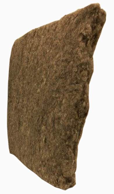
Figure 6 – Sheeps Wool used throughout this research
Sheeps wool used for insulation is generally a by-product from the farming industry meaning that the supply can vary and the cost can be high as the infrastructure and economies of scale have not yet been put into place. Every year the average sheep produces between 2.3 and 3.6 kg of raw wool that must be sheared for the health of the animal (Corscaddena, et al., 2014) and as there are currently 11.2 million sheep in England (Department for Environment, Food & Rural Affairs, 2017), this equates to an average of 33 million kilograms of wool being produced each year. This simple calculation shows how widely available this natural resource currently is.
The main benefit of sheeps wool is that it can absorb a significant amount of moisture from its surroundings, without loosing its thermal properties (Korjenic, et al., 2015), therefore providing a more stabilised internal environment with lower peaks in relative humidity. Other advantages of sheeps wool also include the fact that it is a naturally occurring material meaning that its embodied carbon is lower, its installation time is reduced as there is no human health risks and it is eco-friendly making it easy to recycle (Zacha, et al., 2012). It has also been found that sheeps wool, along with other fibrous materials, has the ability to absorb harmful airborne contaminates, therefore improving the health benefits further (Curling, et al., 2012).
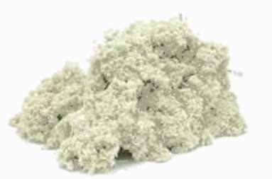
Figure 7 – Cellulose used throughout this research
By up cycling newsprint and other forms of waster paper, cellulose has low levels of embodied energy associated with it. One of the key advantages to this material is the fact that it can be installed by means of blowing the materials into place, which means a continuous layer can be created, which is a similar advantage to that of SPF’s, it means that it can be easily applied to the refurbishment of existing dwellings.
Currently in the UK we produce 790,432 tonnes of newsprint print every year and if you look at the global scale the total production is close to 25 million tonnes (Food and Agriculture Organization, 2015). These numbers highlight the size of the paper industry. Obviously, all this paper cannot be used for insulating purposes as a significant proportion of the paper and board industry are already significantly dependent on recycled paper, as 70% of the fibres used is from re-cycled paper (CPI, 2016). The excess however could be utilised to create more cellulose insulation, for example in 2012 the UK exported 4.5 million tonnes of paper (CPI , 2013). This amount of raw materials could potentially be treated and made available for homeowners to insulate their homes.
The highest proportion of the embodied energy of cellulose comes from its fire protection measures, as borax is added to prevent the shredded paper particles from catching fire. Borax is a naturally occurring mineral and therefore it must be mined to acquire it. It is also considered to be slightly toxic, although in low doses it is considered safe (An & Xue, 2014). Despite this component of the manufacturing process, the associated embodied carbon is still relatively low and the health impacts with handling the material are insignificant.
6.2.3 – Wood Fibreboard (STEICO)
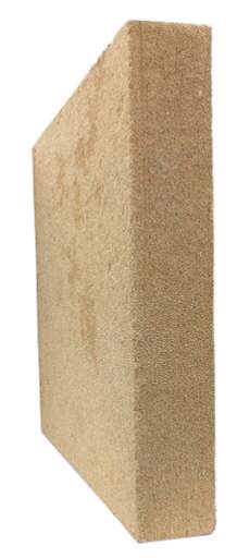
Figure 8 – Wood Fibreboard used throughout this research
Due to the wide range of densities available for wood fibreboard it is slightly different to the other two bio materials under consideration. The range in density means that it can be used for nearly all insulating needs and is the only material under consideration that can be installed externally, only requiring an additional layer of render to protect it from the elements.
The key environmental benefit associated with this material is that it has a negative carbon impact. This is caused by the fact that the manufacturing process is 90% less energy intensive than some man made materials (Black Mountain, 2016) and because wood stores carbon during its growing phase and throughout its lifespan (Sutton, et al., 2011).
The wide spread availability of wood is huge, however farming timber has to be done in a sustainable way to ensure that this material remains an environmentally friendly alternitive. Most of the wood that is used for insulation comes from spruce or fir trees and they are mainly off cuts or waste materials from other timber industries, meaning that this insulating solution is another form of up cycling. Wood fibre is easily installed as it is not harmful to humans meaning, like other bio materials, protective clothing is not required, its rigid shape also enables storing and moving into place easier.
7.0 – Laboratory Experimentation
Hygrothermal simulations, like WUFI, are a great tool for its user, however the output that it provides can only be as good as the inputs defined by the user. Therefore, in order to get a good approximation of the use of hygroscopic materials as an alternative to vapour barriers the most sensitive parameters for the model were obtained in the laboratory.
The results can also contribute to a potential database of hygroscopic materials which will help encourage the use of bio-based materials in the future. This is because it is their nature to have high levels of variation and can be more unpredictable compared to man-made alternatives, as mentioned in Section 6.1.7.
The materials bulk density, thermal conductivity and moisture storage isotherms have been determined via physical experimentation as part of this research and are reported in Section 7.2.
The bulk density was measured in accordance with BS EN 1602 (1997) and has been reported in kg/m3, with repeats being performed to ensure that the values obtained are precise. By using a sample size of 600 mm by 600 mm with constant thickness, meant that a representative value of the whole material could be determined.
7.1.2 – Moisture Storage Isotherms
Both the absorption and desorption isotherms were determined by using a dynamic gravimetric water sorption analyser (DVS Intrinsic), as shown in Figure 9. Both the isotherms were measured in order to determine the hysteresis effect for each material, showing how much the desorption isotherm lagged behind the sorption isotherm.
The DVS Intrinsic apparatus enables the user to control the environment of the sample chamber, meaning that various humidity steps could be measured during the experiment, leading to a more accurate approximation of the sorption isotherms. All the tests were performed at 20C, with the relative humidity being increased gradually from 0% to 95% and back down to the 0%. The relative humidity step changes were; 0%, 15%, 30%, 45%, 60%, 75%, 95%, where the apparatus was set up to automatically move to the next step of the test once equilibrium was determined. The experiment did not look at the relative humidity range 95% – 100% because in this area materials begin to act differently as they begin to absorb liquid water via capillary action (Kumaran, et al., 1994).
The samples used during these experiments were only small ( 990mg) and therefore it was difficult to be confident that the samples were representative of the material. To reduce this uncertainty, three samples of each material were taken from different locations and then tested with the same methodology and from this an average was taken.
The thermal conductivity of the materials were tested in accordance with BS EN 12664 (2001), using the heat flow meter methodology. The samples used were the same as the ones used to measure the bulk density to ensure consistency in the results. The thermal conductivity was obtained at average temperature of 10°C, 20°C and 30°C, so that a temperature dependent thermal conductivity could be reported and included within the hygrothermal simulation.
As well as performing the test at the 3 different temperatures, each sample was tested once when dry and once after being conditioned at a temperature of 20C and 50% RH. This was done to get information on how the materials thermal performance is affected by a rising moisture content.
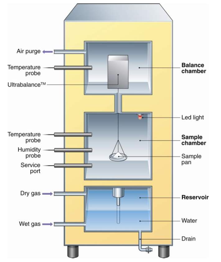
Figure 9 – DVS Intrinsic apparatus schematic (Surface Measurement Systems Ltd, 2015)
The values were obtained by the method laid out in Section 7.1.1 and were then compared to manurfacures’ specifications, shown in Table 2. The uncertainty of sheeps wool and cellulose insulation is a particular issue concerning the products. The materials are very compressible, meaning it is difficult to produce repeatable results, as even under the materials self weight a certain amount of settling will occur. For the purpose of this report the values used throughout the research were the measured values and not the values specified by the manufactures.
Table 2 – Measured bulk densities
| Density (kg/m3) | Manufactures Specification (kg/m3) | Uncertainty (%) | |
| Sheep Wool | 34.1 | 19a | 44 |
| Cellulose | 76.6 | 45b | 41 |
| Wood Fibreboard | 140.1 | 140c | – |
|
|||
7.2.2 – Moisture Storage isotherms
The moisture storage functions were determined using the method outlined in section 7.1.2 and are shown in Figures 10 – 12. The absorption isotherm was then directly imported into the hygrothermal simulation to improve its accuracy.
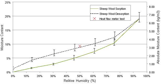
Figure 10 –sheeps wool isotherms for sorption and desorption
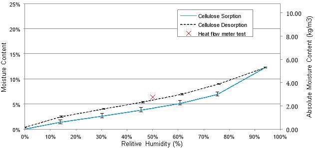
Figure 11 – Cellulose isotherms for sorption and desorption
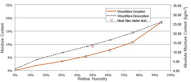
Figure 12 – Wood Fibreboard isotherms for sorption and desorption
These findings show that sheeps wool and cellulose insulation accepts moisture more readily than wood fibreboard relative to its mass. This is in line with what was expected, because wood fibre is significantly more dense than the other two materials. It is also interesting to note that conditioning the samples to 50 % relative humidity at the start of this research caused the samples to release moisture, indicating that they had previously been located in an environment of higher humidity. This is shown as the heat flow meter data points lie along the desorption isotherm, indicated by a red crosses.
The error bars for each of the materials have also been shown, this was deemed appropriate due to the difficulty of maintaining a constant density and size for each tested sample. Wood fibreboard was relatively straight forward as the material is fairly solid. However cellulose and sheeps wool were difficult to repeat reliably, due to their high compressibility and nature to disperse, these differences between materials explain the higher error bars in the sheeps wool and cellulose materials, compared to the wood fibre.
- Sheep Wool b) Cellulose Insulation
- Wood FIbreboard
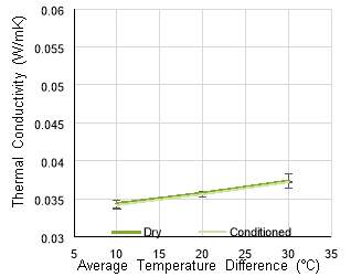
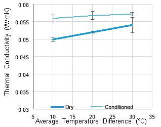
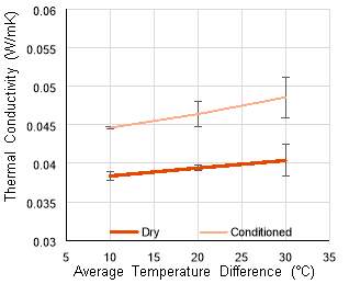
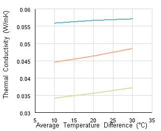
Figure 13 – Thermal conductivity, temperature and moisture dependency
The results above show that all of the hygrothermal materials being tested are comparable in terms of their dry thermal conductivities, with sheeps wool performing the best with a thermal conductivity of 0.0357 W/mK at 20C and cellulose performing the worse with 0.0540 W/mK. Although there is a 51% range between the materials in these findings, they are all in the same order of magnitude, making them relatively similar in terms of insulating performance and putting them in the region of expanded polystyrene (0.0450 W/mk) and mineral wool (0.0325 W/mK).
It can be seen that the thermal conductivity of sheeps wool is not influenced by increasing its moisture content from 0% to 9%. This is an expected result that agrees with the findings of Section 6.2.1 and means that this material is ideally suited for hygrothermal uses.
- Dry samples b) Conditioned Samples
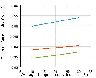
Figure 14 – Thermal conductivity comparisons
By comparing the three materials together on one graph enables an easier comparison. The key point that can be see here is that the gradient of line of sheeps wool and wood fibre appears to be more shallow than that of cellulose insulation, when the samples are dry. This shows that these two materials are slightly less sensitive to changes in temperature, when dry. This seems to be the opposite in the conditioned samples, the sensitivity to temperature of the cellulose seems to decrease with a higher moisture content, where as the sensitivity of the other two materials increases.
Both of these values will be imported into the hygrothermal simulation, in order to determine the actual thermal performances of the scenarios being tested.
To answer the hypothesis in section 5.1, the approach was to run a one-dimensional heat and air transport model within Wärme- Und Feuchtetransport Instationär (WUFI).
WUFI is a German produced simulation for moisture and heat transfer through the external fabric of a building. It is one of the most widely used hygrothermal simulations currently available and it is also one of only two models that are validated in accordance with BS EN 15026 (Bludau & Little, 2017). By using WUFI it is possible to produce a more accurate representation that accounts for the hygroscopic properties, compared to the common Glaser method, which is part of DIN 4108.3 (2002). This is due to the limitations of the of the Glaser method, as it does not consider the materials sorption capacities or their moisture transport capacities, WUFI on the other hand has the ability to include these parameters.
The cases performed during this research were done over simulated 6 year period. The initial 3 years were done using the control case, which then provided the starting point for running cases 2-10 for another 3 years. All the cases are shown in Table 3 and the wall build ups are outlined by Figure 17. By allowing the model to reach equilibrium initially, before swapping it for its hygrothermal replacement enabled the impact of this change to be easily analysed.
The thickness of the hygrothermal materials were varied so that the impact could be determined. Making it possible to determine what thickness, if any, is required to create a wall build up which behaves like the control case and create areas of high relative humidity.
| Control | Bio-Based Alternative Thickness | |||
| 10 mm | 20 mm | 30 mm | ||
| Vapour Barrier | Case #1 | |||
| Sheep Wool | Case #2 | Case #3 | Case #4 | |
| Cellulose | Case #5 | Case #6 | Case #7 | |
| Wood Fibreboard | Case #8 | Case #9 | Case #10 | |
The external weather file was taken from Bristol, as its geographical location is very close to the University of Bath. The annual temperature variation is shown in Figure 15 and the annual driving rain data is shown in Figure 16. As Bristol is only 20km away, the variation in annual weather data is small and therefore it is valid to assume that the two cities are identical.
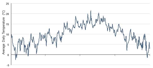
Figure 16 – Annual average temperature data, Bristol, United Kingdom
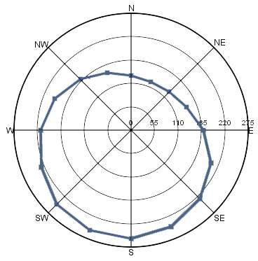
Figure 17 – Annual driving rain data, Bristol, United Kingdom
The orientation of the wall was set to face due south, this was done to create a worst-case scenario of the timber construction as it maximised the walls exposure to driving rain which is expressed by Figure 16. For reference and repeatability, then other factors that were added into the model to get a better representation have been included tabulated in Table 4.
The internal climate used for this research was calculated automatically by the WUFI software. The calculation was based on the internal environment having a ‘medium moisture load’ and being dependent on the external climate, due to adequate ventilation. All of this is therefore in accordance with BS EN 15026 (2007).
Table 4 – Additional input data for the WUFI Simulation
| Input | Value |
| External Surface Heat Resistance | 0.0588 (m2K/W) |
| External Sd-Value | 0 (-) |
| Short-Wave Reflectivity | 0.4 (-) |
| Adhering Fraction of Rain | 0.7 (-) |
| Internal Surface Heat Resistance | 0.125 m2K/W (-) |
| Internal Sd-Value | 0 (-) |
The wall that was tested within this research is based on the timber framed construction previously mentioned in Section 6.1.3.3. The control case is shown in the first drawing of Figure 17. The make-up consists of wooden cladding and an air gap to provide protection from the driving rain within the Bath location. After that a breathable membrane allows vapour to escape to the outside. The timber studs and the mineral wool insulation are behind the breather membrane and on the inside face there is a vapour barrier and a layer of standard thickness gypsum plaster board.
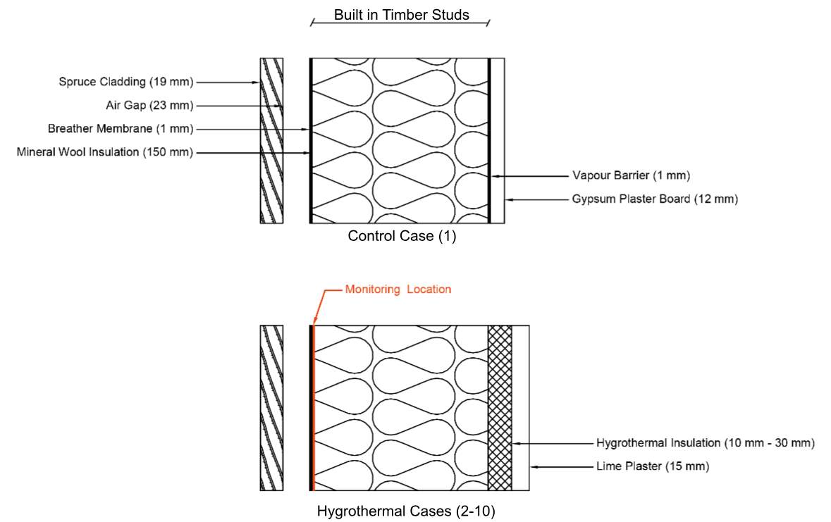
Figure 18 – One dimensional wall build-ups of considered cases, including monitoring location.
All other cases being performed during this research differed from the control case by replacing the interior facing gypsum plaster board and vapour barrier with a breathable lime render along with varying thickness of either sheeps wool, cellulose insulation of wood fibreboard. For the purpose of repeatability, the additional materials used during the research, along with their key properties have been provided within Appendix A.
As shown in Figure 17 the key monitoring point of this wall construction was deemed to by the external face of the timber studs. This was chosen as the geographical location of the simulation is in an environment where the external climate normally has a greater relative humidity than the internal climate. This difference will be the driving force of moisture through the wall, meaning that the highest humidity for the vulnerable timber studs will be at this monitoring position.
8.2.3 – Material Properties for Bio-Materials
The material properties that have not been obtained via experimentation have been deemed to be less influential to the accuracy of a hygrothermal simulation (WUFI, 2017). As a result, the values of these properties have be determined from the manufactures technical sheets and the literature. An extensive search of available materials on the market today has been performed in order to give confidence on the values used in Table 5, however they will not be independently validated as part of this dissertation, meaning that these could be determined in the future in order to improve the accuracy of the simulation.
Table 5 – Material properties for the hygrothermal simulation
| Porosity
(m3/m3) |
Specific Heat Capacity (J/kgK) | Water Vapour diffusion Resistance Factor (-) | Typical Built in Moisture (kg/m3) | |
| Sheep wool a | 0.98 d | 1700 | 1 | 4.30* |
| Cellulose b | 0.93 e | 1600 | 1 | 6.36* |
| Wood Fibreboard c | 0.91 f | 2100 | 3 | 17.60* |
*Typical Built in moisture was determined by interpolating the moisture storage function to obtain the w80 value. |
||||
In order to approximate the liquid transport coefficients, then additional material properties were required. These were taken from similar products found within the WUFI database and are shown in Table 6.
Table 6 – Approximated water absorption data
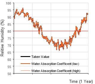
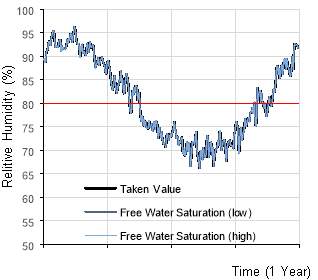
| Water Absorption Coefficient, A-Value (kg/m2√s) | Reference Water Content, w80 (kg/m3) | Free Water Saturation, wf (kg/m3) | |
| Sheep Wool a | 0.000342 | 4.3 | 18.04 |
| Cellulose b | 0.56 | 6.36 | 500 |
| Wood fibreboard c | 0.0033 | 17.6 | 526 |
|
|||
From these additional properties the liquid transport coefficients for sorption and desorption could be approximated by and inbuilt equation within WUFI. This method of assigning the liquid transport coefficients is highly uncertain, although it is believed that the sensitivity of the model to variations of this property is very low.
Two effects of replacing the vapour barrier with hygrothermal materials have been looked at during this project, both of which impact the overall performance of the wall in question.
8.3.1 – Relative Humidity Accumulation
In order to determine whether this modification would lead to an unwanted increase in mould and rot, it was essential to determine where the key levels of water vapour would occur and whether these were with in the acceptable thresholds. As the humidity was not going to be low enough for health issues related to low levels of humidity to become problematic (Arundel, et al., 1986), only the upper threshold has been considered.
In normal timber frame design, Sitka Spruce is a common type of timber (Smith, 2013) and for soft woods like this, it is deemed dangerous to allow the moisture content to exceed 20% for any prolonged period. This moisture content threshold relates to a relative humidity of 90% as calculated from the moisture storage function of Sitka Spruce (Hill, et al., 2010). Although 90% has been shown to be the ultimate limit a more conservative threshold of 80% has been deemed appropriate, which is in accordance with BS 5250 (2011). By lowering the threshold down to 80%, shown by the red line in Figures 18 – 21, it accounts for other potential factors that may encourage mould growth and limits the potential for issues that were highlighted in section 6.1.3.4.
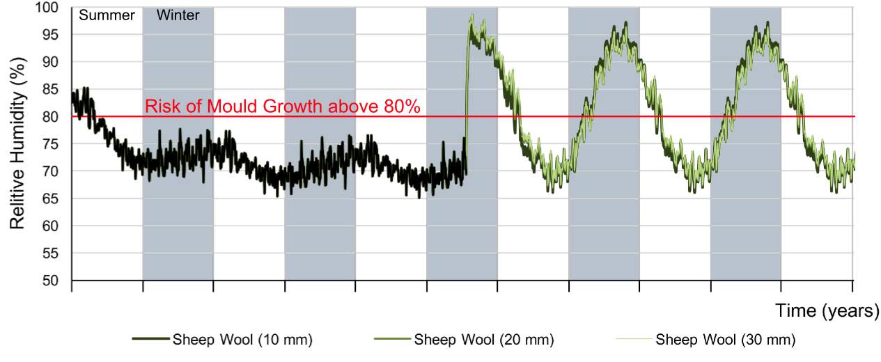
Figure 19 – Critical relative humidity, with various thicknesses of sheeps wool
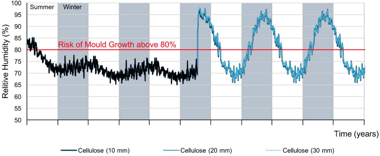
Figure 20 – Critical relative humidity, with various thicknesses of cellulose
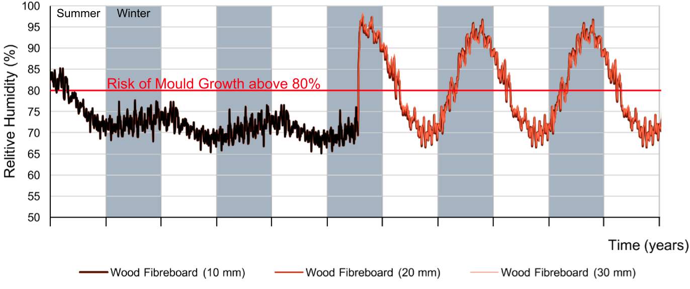
Figure 21 – Critical relative humidity, with various thicknesses of wood fibreboard
Figures 18 – 20 show how the relative humidity at the critical monitoring position is impacted by the replacement of the vapour barrier. A sudden transition is a common feature and as a result the average humidity exceeds the 80% threshold. It is interesting to note that by varying the thickness of the sheeps wool, cellulose or wood fibre it has a very little impact to the behavior of the wall, suggesting that a hygrothermal replacement for a vapour barrier is not an option.
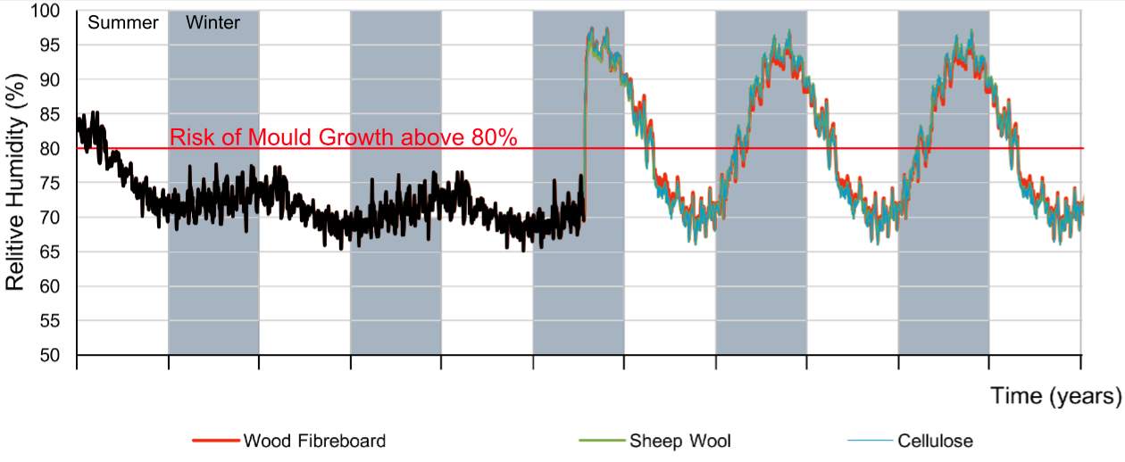
Figure 22 – Comparison of the critical relative humidities between materials
By comparing the sheeps wool, cellulose and woodfibre board against each other it is clear to see that the reduction of water vapour within a wall is not highly sensitive to either the density or material of the hygroscopic material. Also suggesting that hygroscopic materials are not a valid substitution for a vapour barrier.
8.3.2 – Thermal Performance Impact
By introducing additional moisture into the wall, it will effect the thermal performance of the materials on top of causing the the humidity in the components to rise. This reduction in thermal performance, is heavily dependent on the sorption isotherms and the the materials thermal conductivity’s sensitivity to moisture. In Figure 22 the representative U-Values of each wall scenario has been calculated, both assuming dry conditions and the actual condition the wall will be in. All the thermal conductivity values used in these calculations, which have been derived from moisture dependent thermal conductivity charts, have been tabulated in Appendix B.
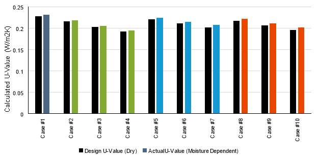
Figure 23 – Dry U-values compared with actual U-Values
It is key to note that a smaller bar in Figure 22 represents a better thermal performance. From this figure it can be taken that the addition of more thermal insulation, even as small as 10 mm, is sufficient to have a bigger positive influence than the negative effect of the increase in moisture.
The results shown in Section 8, do not fall in line with the hypothesis of this research. The sudden increase in the critical humidity at the change from the control case to the hygrothermal replacement, indicates that the two types of materials have very different uses in wall construction.
This can be further emphasised by looking at the critical monitoring location of the relative humidity profiles of each wall, as shown in Figure 23. The control case (a), shows a sudden drop in relative humidity from 48% to 31% at the vapour barrier surface. Where as the hygrothermal materials do not provide the same reduction in humidity, instead the relative humidity is allowed to pass through the material freely which in turn leads to a high humidity at the critical location.
The reduction of 17% in relative humidity that is provided by the vapour barrier means that the critical humidity at the outer face of the mineral wool stays below the 80% mould threshold. Another benefit that the vapour barrier has compared to the hygrothermal materials, is its ability to stabilise the environment within the wall. This explains the reason behind the bigger variations of the hygrothermal materials shown in Figures 18 – 21 and the bigger spread of humidity values shown in Figure 23.
9.1 – Critical Monitoring Location Justification
As can be seen in Figure 23 the critical monitoring position that was used throughout this research is the point of highest relative humidity. There maybe situations where the humidity is higher in the cladding and air gap, however this is expected as these layers are designed to absorb and deflect driving rain in order to protect the main wall construction.
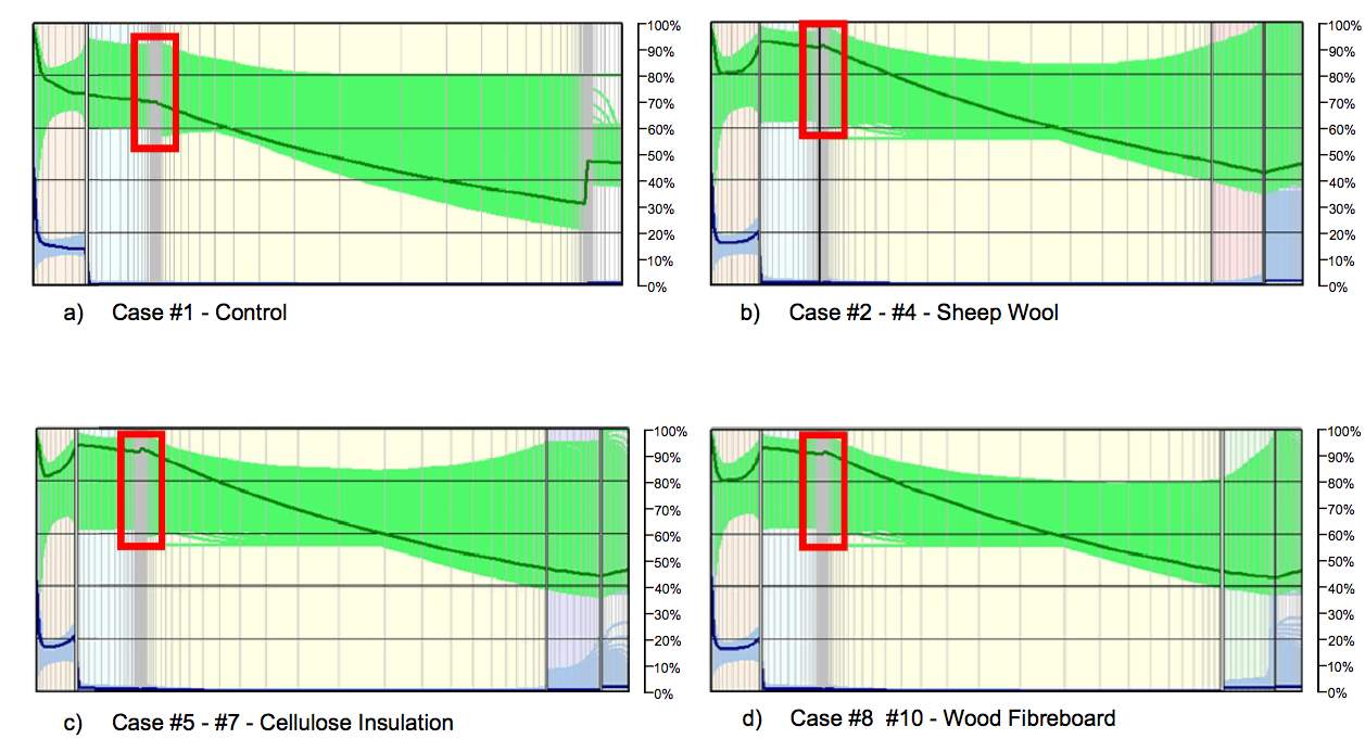
Figure 24 – Relative humidity profiles for WUFI simulations for all cases
9.2 – Sensitivity to Variations in Material Properties
As the reported results were dependent on more approximated properties than experimentally determined values then the results have a high level of uncertainty. It was deemed acceptable to determine certain parameters by researching the literature and manufactures technical data, as the hygrothermal model’s sensitive to these parameters was considered to be low. In order to justify this, upper and lower values were analysed in the model to determine its sensitivity to these properties.
Only the sensitivity of the critical monitoring position in case #3 has been checked for this project. This was deemed sufficient to understand whether any of the parameters create a significant difference to the final reported results. All sensitivity checks were performed by applying a +/- 15% on the given value as shown in Table 7.
Table 7 – Upper and lower bound sensitivity values
| Lower Value | Value used in research | Upper Value | |
| Porosity (m3/m3) | 0.82 | 0.96 | 1.00* |
| Water Vapour Diffusion Resistance Factor (-) | 0.85 | 1.00 | 1.15 |
| Water Absorption Coefficient(kg/m2√s) | 0.000291 | 0.000342 | 0.000393 |
| Free Water Saturation (kg/m3) | 15.33 | 18.04 | 20.75 |
|
*The upper value for porosity must be between 0 and 1, meaning the maximum value is 1
|
|||
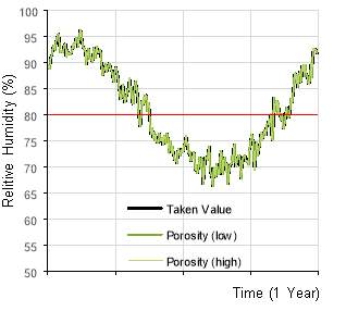
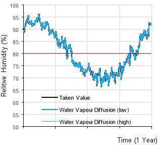
- Porosity b) Water Vapour Diffusion
- Water Absorption Coefficient d) Free Water Saturation
Figure 25 – Upper and lower bound sensitivity checks
As can be shown by Figures
Figure 24(a) –
Figure 24(d) the hygrothermal model does not show any signs of sensitivity to changes in porosity, water vapour diffusion factors, water absorption coefficients or free water saturation values. This provides greater confidence on the reported results in Section 8.3.
To ensure that these parameters also didn’t effect another location with in the wall construction, a visual analysis was performed on the relative humidity profiles across the walls. This agreed with
Figure 24, as there was no noticeable difference between the results.
9.3 – Mass Spectrometry Imaging
Mass Spectrometry was used as an attempt to gain an approximation of the porosities of each material. Unfortunately this could not be achieved due to the lightness of the materials in question and the limit to the sample sizes possible to image. Instead the equipment was used in order to gain a better understanding on the materials structure and to possibly justify why the materials exhibit the hygrothermal abilities shown by the experiments performed as part of Section 7.2.
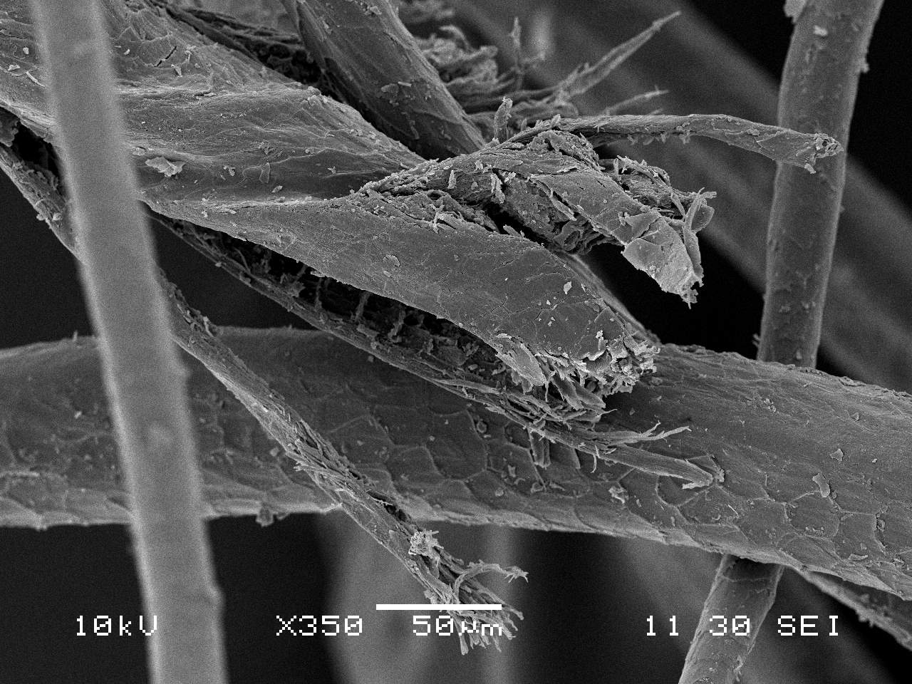
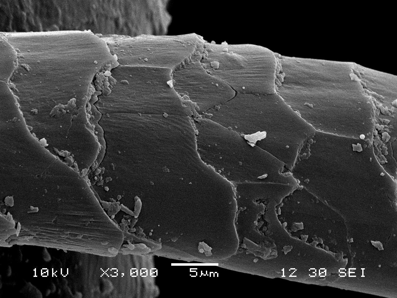
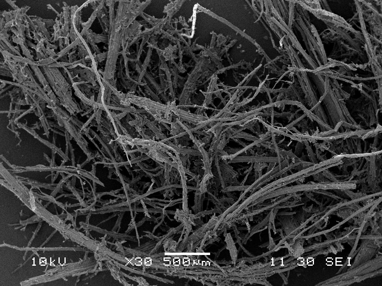
- 30x magnification b) 350x magnification c) 3000x magnification
Figure 26 – sheeps wool taken from mass spectrometry imaging
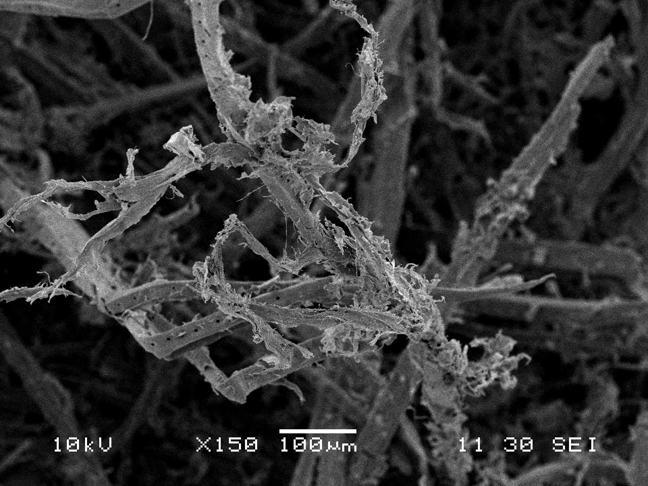
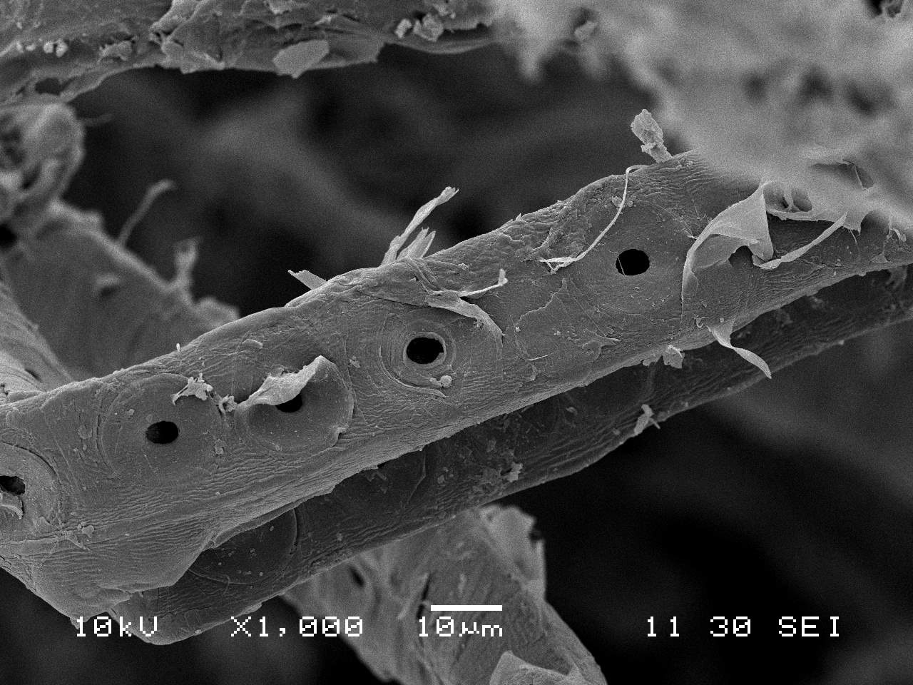
Figure 25(a) shows an interwound material structure with a high levels of porosity. The significant amount of air pockets that are created as a result of this structure is the main reason why sheeps wool exhibits good thermal properties. A closer view of the individual wool strands shown in Figure 25 (b) and (c), could shed light on how the material is able to absorb a significant amount of moisture without loosing its thermal performance. Its ribbed surface enables more moisture to adhere to the strands, therefore not significantly reducing the size of the internal air pockets, which as mentioned above is the key component to the materials thermal properties.
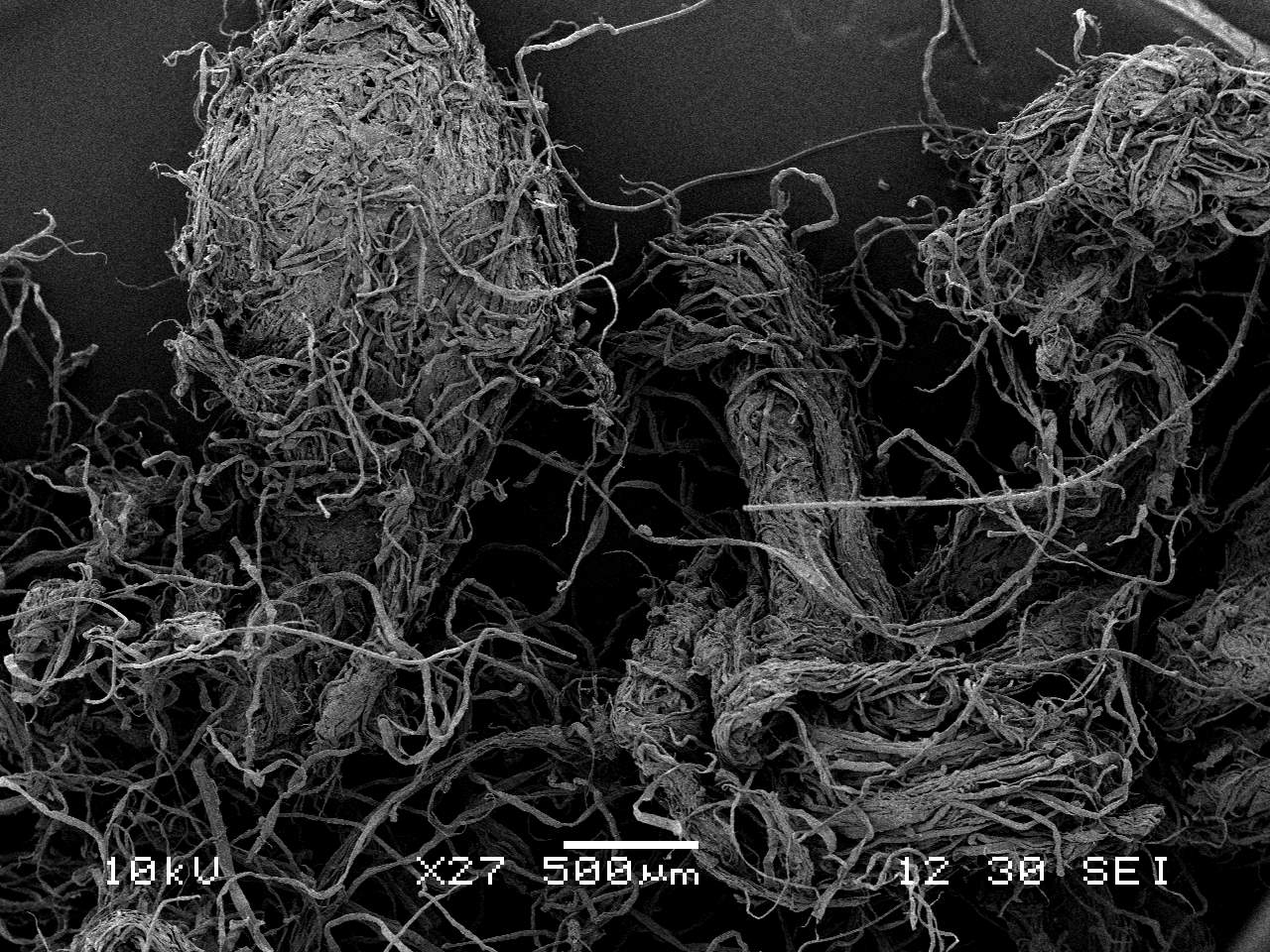
- 27x magnification b) 500x magnification c) 7000x magnification
Figure 27 – Cellulose taken from mass spectrometry imaging
Cellulose on the other hand does not have the same levels of porosity within the materials particle structure. It is clear in Figure 26(a) that each individual particle is relative dense, in comparison to sheeps wool. This leads to the confusion that the thermal properties of cellulose comes from the air pockets created in-between each particle and not by the structure itself. This would mean that as the particles are forced closer together, increasing the density and reducing the porosity, the thermal performance of cellulose will be negatively impacted which is in line with the findings of Sekino (2016).
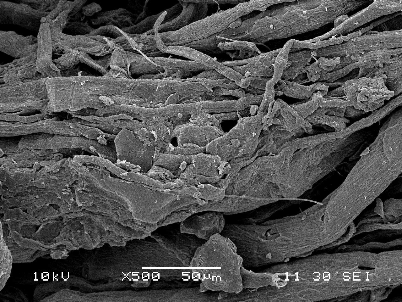
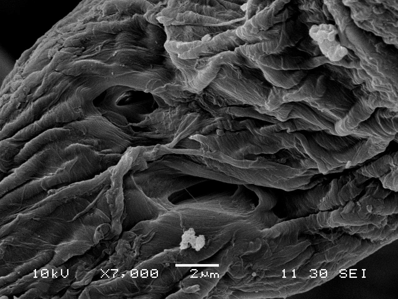
- 30x magnification b) 150x magnification c) 1000x magnification
Figure 28 – Wood Fibreboard taken from mass spectrometry imaging
The material structure of wood fibreboard, as shown in Figure 27(a), is similar to that of sheeps wool and not the cellulose insulation. The particles are long interweaved strands that in turn create the air pockets that provide the thermal performance. The strands are more compact compared to sheeps wool, which is expected due to the differences in density, meaning that its porosity would be lower and its thermal conductivity would be higher, this is in line with the findings of this report shown in Figure 14 and Table 5.
This research was performed in order to determine the feasibility of replacing a vapour barrier with an alternative hygrothermal material. This was deemed a useful part of research as materials likesheeps wool, cellulose and wood fibre all contain less embodied energy, along with comparable thermal performances. The relative humidity of the wall construction being tested was expected to rise, due to the removal of the immediate vapour control. However, it was hypothesised that by gradually increasing the thickness of the hygrothermal layer, an optimum point could be found were the wall would act in a manner similar to its vapour controlled alternative, along with having a better U-Value as a result of more insulating materials.
10.1.1 – Laboratory experimentation
The isotherms obtained via the use of the DVS intrinsic follow a pattern that was expected, however due to the limitation of 7 steps in relative humidity a good understanding of how the materials act at every possible point on the relative humidity range is lacking from this research. In order to get a better understanding of the materials behaviour then the moisture storage experiment would need to be repeated, with a much lower interval of the relative humidity between steps. This will take a substantial amount of time due to the nature of the experiment, however it will create results that are more accurate as the amount of interpolation will be reduced.
The reported isotherms of cellulose and woof fibreboard in Figures Figure 11 and Figure 12, conform with findings reported by Hurtado, et al. (2016) and Vololonirina, et al. (2014). However the isotherm obtained for sheeps wool, does not seem to agree with the reported findings in the literature (Zacha, et al., 2012). The moisture contents calculated during this research seem to be significantly lower than other reports, so much so that differences in the temperatures at which the experiments were performed can not explain the discrepancy. For example, at 50% relative humidity Zacha, et al. saw a moisture content of 21% and at the same humidity this research found a moisture content of 6%. On top of this the findings of Zacha, et al. also show a region of plateau between 35% and 70% relative humidity, something which is not evident on the findings of this report. The variation in levels of moisture content is likely to have stemmed from the large discrepancy in the measured bulk density compared to the manufactures specifications explained in Section 7.2.1, however the absence of the region of plateau is not explained by this. By combining the size of the error bars with in Figure 11 along the discrepancies with previous research therefore raises uncertainty about the findings of this research.
The methodology used to determine the moisture storage isotherms also becomes in accurate once the relative humidity surpasses 95%, this is because past this point the material begins to absorb liquid moisture as well by means of capillary action, creating a significantly higher moisture content than that achieved whilst materials are in their hygroscopic region of 0% – 95%. This explains the rapid increase in moisture content predicted by Oswin model (Owsin, 1946 cited by Hurtado, et al., 2016). As the range of humidities of 95% – 100% were therefore ignored during the experimentation, it lead to uncertainties in the simulation as the liquid transport coefficients had to be approximated by an algorithm that was built into the WUFI software.
Although the dry thermal conductivity values seem to be in line with what was expected and agree with the manufactures specification, tabulated in Table 1, the conditioned samples with moisture contents between 4% and 6% may not be representative of the in service values. This is due to the limitations of the heat flow meter, when measuring moist materials, as it can not account for the effects of phase changes, moisture movement and vapour diffusion (Langlais, et al., 1994). As a result of this uncertainty in the actual thermal conductivity then the reported actual U-Values in Figure 22, may not be fully representative of the in service performance of each wall build up.
10.1.2 – Hygrothermal Simulation
The computer model can only be as accurate as the information obtained from the laboratory experiments, meaning that the uncertainties with the sorption isotherm of sheeps wool and the bulk density measurements of sheeps wool and cellulose were carried over into the simulation. However as the behaviour of all three materials were found to by similar, as shown by Figure 21, then it can be concluded that the uncertainties of the physical experiments did not have a significant impact on the final findings of this report.
The limitation of not being able to account for the hysteresis effect of the materials, would have impacted the final results, as the simulation assumed that the materials would release the moisture stored as readily as they absorbed it. This has been shown to be an un-conservative assumption by Figures 10 -12 as the materials retain more moisture during desorption then during sorption, meaning that over time the problems found in Figures 18 – 21 maybe more extreme due to the fact that the material my not be given sufficient time to dry out, leading to a slow build up in moisture.This limitation of the simulation will not however change the conclusions of the report as it will only worsen the findings.
The significant amount of the material properties that had to be taken from the literature or approximated by the in-built algorithms of WUFI, has the potential to raise questions about the findings obtained. The material property that raises the most uncertainty is the free water saturation of sheeps wool, included in Table 6. This value was taken from data related to another form of sheeps wool, that was already present in the WUFI material database, however it seem unrealistically low when compared to the other two materials and it is suggested that this material property should be obtained via experimentation if this research were to get repeated.
Apart from the uncertainty of the free water saturation of sheeps wool, it seems acceptable to ignore the uncertainties of the material properties for this research. This is because it was shown with Figure 24 that the simulation was not sensitive to variations in any of the parameters that were taken from the literature. Obviously if future work requires a full accurate representation of the total behavior of the wall then this would be insufficient for that requirement and more material properties would be required to be measure via laboratory experiments.
In order to ensure more confidence with the results obtained from this research then a physical representation of the wall construction could be built and tested, to determine whether the it performs in the same manner as predicted in these findings (English Heritage, 2010). However, this will require investment as scale models are expensive to run and because the findings are negative then investment into this area may not be the best area of investment and research.
10.2 – Limitations to the findings
WUFI as a software is a great tool for designers, however it has to assume that the wall is constructed perfectly in order to able to run and it can obviously not predict potential errors made during the construction phase caused by bad workmanship or inexperience. It also has to perform its calculations with a limited database of climatic information (Milsom, 2014), meaning extreme weather scenarios will not be covered by this analysis, something which could become more common in the future. As a result the findings of the research represent the best possible outcome and in reality it is likely that the findings will be worse then those observed here.
Along with WUFI, the hand calculations used to determine the actual U-Values of the walls considered had to assume a perfectly constructed wall. In reality materials like cellulose and sheeps wool will begin to settle under their own weight. Even during the experiments of this research it was difficult to maintain the same density through out, due to the materials nature of settling and compacting. In service, this issue will inevitably lead to gaps forming at the top of the walls in which the insulation in installed, leading to effectively a short circuiting of the system, by creating cold spots in the wall, were heat can be easily lost. This is also a problem that was outlined by Hurtado, et al. (2016) in their research on the properties of cellulose insulation.
This research set out to determine the potential use of hygroscopic materials as a replacement for vapour barriers used during timber construction. It was deemed important as wall behaviour and breathability is commonly neglected and solutions to wall constructions are usually chosen by the means of common practice instead of research, meaning issues with mould and poor performance are more common than they should be. By providing information on the benefits of alternative insulate products it was also an aim to improve the understanding of the benefits of hygroscopic materials along with showing why insulation as a whole is a vital component in reducing our demand on energy in the future.
The findings show that hygroscopic materials are not a valid alternative to the use of vapour barriers as they do not absorb a sufficient amount of moisture in order to prevent unwanted extremes in relative humidities with in the wall construction. This Means that for the Bath and Bristol area of the United Kingdom the traditional vapour control methods in timber buildings is still advised. A good example of the transport of moisture has been shown in Figure 23 which can be used to justify the use of vapour barriers within a typical timber wall construction. However, as this research is only focusing on one type of construction it should be noted that further analysis should be performed on an individual basis, as even the slightest of modifications can have a significant impact on the moisture distribution within the wall.
Another noteworthy finding that can be taken away from this research is that out of the three hygroscopic materials tested, all of them improved the thermal performance of the wall, meaning that even the addition of 10 mm of hygroscopic insulation out weighs the negative effects that higher moisture contents have on the thermal conductivities of the materials tested. This can not be taken as a general rule however as all materials have different sensitivities to exposure to moisture.
Ideally this report would have opened up further research into the area of alternatives to vapour barriers, allowing external walls to breathe and therefore improving the health of the occupants. Unfortunately the conclusions of this research were that hygroscopic materials are not a viable option to replace the vapour control layer within timber construction in the UK. However, the potential uses of hygroscopic materials are wide spread, meaning that the further research can be done in different uses of the materials, along with different wall constructions. The positive that can be taken from this report is that its uses as a vapour barrier is not viable, therefore eliminating its requirement to be researched further.
The process undertaken to reach the conclusions in Section 11 lead to an improved understanding of hygrothermal modelling, along with the current limitations that it incurs. The findings that were reported in the literature review provided a good insight in the benefits hygroscopic materials and in particular, naturally occurring bio-based materials, along with their potential use as alternatives to man made insulation and the experimental properties can be reused as reference data for design purposes or future analysis.
During the research it was realised that an British database containing the hygrothermal properties of building and insulating materials like the ones available in Germany would be a very useful tool for practicing engineers to use. This would provide an effective one-stop-shop for material information, meaning that materials could be more standardised, therefore encouraging the usage of alternatives to the three main insulating materials of mineral wool, polystyrene and polyurethane foam. This was also a finding of Browne (2012) and although it is a big undertaking, its potential benefits could be significant in replacing high energy products with lower energy alternatives.
Along with the suggested work on creating a material database and a standardised methodology for determining the material properties. The hygothermal model created could be used and modified to analyse different climatic conditions, orientations and wall constructions as mentioned in Section 6.1.3. It could also be further calibrated with physical modelling and further improved by performing additional experiments that are required as inputs into the hygrothermal simulation. The next material property that is advised to be determined via experimental means is the liquid sorption characteristics as this has been deemed to be the parameter the the model is most sensitive to after the moisture storage functions, as it will provide a more accurate understanding on how liquid water flows through the wall construction on top of the transport of moisture that has already been determined.
Department of Energy and Climate Change, 2012. Green Deal: energy saving for your home. [Online]
Available at: https://www.gov.uk/green-deal-energy-saving-measures/overview
[Accessed 10th April 2017].
Al-Homoud, D. M. S., 2005. Performance characteristics and practical applications of common building thermal insulation materials. Building and Environment, Issue 40, pp. 353-366.
AMA, 2015. Building Insulation Products Market Report – UK 2015-2019 Analysis, Cheltenham: AMA Research.
An, J. & Xue, X., 2014. Life cycle environmental impact assessment of borax and boric acid production in China. Journal of Cleaner Production, Issue 66, p. 121–127.
ANPE, 2017. Polyurathane Performance – Thermal conductivity. [Online]
Available at: www.poliuretano.it/EN/thermal_conductivity_polyurethane.html
[Accessed 4th April 2017].
Arundel, A. V., Sterling, E. M., Biggin, J. H. & Sterling, T. D., 1986. Indirect Health Effects of Relative Humidity in Indoor Environments. Enviromental Health Perspectives, Issue 65, pp. 351-361.
BEIS, 2016. Energy Consumption In the UK, London: Her Majesty’s Stationery Office.
Black Mountain, 2016. Natural Wood Fibre Insulation – NatuFlex. [Online]
Available at: http://www.blackmountaininsulation.com/NatuFlex_Brochure.pdf
[Accessed 15th December 2016].
Black Mountain, 2017. NatuWool – Technical Sheet, Bradwell on Sea: Black Mountain Natural Insulation.
Bludau, C. & Little, J., 2017. WUFI Pro: Heat & Moisture Simulation Workshop. [Online]
Available at: www.greenregister.org.uk/civicrm/event/info?id=271
[Accessed 4th April 2017].
Boden, T. et al., 2015. Global Carbon Atlas. [Online]
Available at: http://www.globalcarbonatlas.org/en/CO2-emissions
[Accessed 27th February 2017].
BRE, 2016. Post Installation Performance of Cavity Wall & External Wall Insulation, Cardiff: BRE – Constructing Excellence in Wales.
Brinkley, M., 2007. The Little Known History of the Vapour Barrier. [Online]
Available at: http://markbrinkley.blogspot.co.uk/2007/07/little-known-history-of-vapour-barrier.html
[Accessed 8th April 2017].
British Standard Institute , 2001. Thermal performance of building materials and products – Determination of thermal resistance by means of guarded hot plate and heat flow meter methods – Dry and moist products of medium and low thermal resistance, London: British Standard Institute .
British Standard Institute, 1997. Thermal insulating products for building applications – Determination of the apparent density, London: British Standard Institute.
British Standard Institute, 2002. Hygrothermal performance of building components and building elements — Internal surface temperature to avoid critical surface humidity and interstitial condensation — Calculation methods, London: British Standard Institute.
British Standard Institute, 2007. Hygrothermal performance of building components and building elements. Assessment of moisture transfer by numerical simulation, London: British Standard Institute.
British Standard Institute, 2011. Code of practice for control of condensation in buildings, London: British Standard Institute.
Chapman, R. et al., 2009. Retrofitting houses with insulation: a cost-benifit. Epidemiol Community Health, I(63), pp. 271-277.
Cheng, V. & Steemers, K., 2011. Modelling domestic energy consumption at district scale: A tool to support national and local energy policies. Environmental Modelling & Software, Issue 26, pp. 1186-1198.
CIMA, 2013. Cellulose Insulation Manages Moisture Without Air/Vapour Barriers. [Online]
Available at: http://www.cellulose.org/BuildersContractors/AirVaporBarriers.php
[Accessed 7th April 2017].
Climate Change Act, 2008. Part 1 — Carbon target and budgeting, London: Her Majesty’s Stationery Office.
Corscaddena, K., Biggs, . J. & Stiles, D., 2014. Sheep’s wool insulation: A sustainable alternative use for a renewable resource?. Resources, Conservation and Recycling, Issue 86, pp. 9-15.
CPI , 2013. Recovery and Recycling of Paper and Board – Fact Sheet, Swindon: Confederation 0f Paper Industries.
CPI, 2016. Put Paper First – Fact Sheet, Swindon: Confederation Of Paper Industries .
Curling, S., Loxton, C. & Ormondroyd, G., 2012. A rapid method for investigating the absorption of formaldehyde from air by wool. Journal of Materials Science, Issue 47, p. 3248–3251.
Department for Communities and Local Government, 2010. Code for Sustainable Homes – Technical Guide, London: Her Majesty’s stationery Office.
Department for Communities and Local Government, 2016. Dwelling Stock Estimates: 2015, England, London: s.n.
Department for Environment, Food & Rural Affairs, 2017. Farming Statistics – Livestock Populations at 1 December 2016, London: Her Majesty’s Stationery Office.
DIN, 2002. Thermal protection and energy economy in buildings – Part 3: Protection against moisture subject to climate conditions – Requirements and directions for design and construction, Berlin: Deutsches Institut für Normung.
Doroudiani, S. & Omidian, H., 2010. Environmental, health and safety concerns of decorative mouldings made of expanded polystyrene in buildings. Building and Environment , 3(45), pp. 647-654.
Dunster, A., 2007. Characterisation of Mineral Wastes, Resources and Processing technologies – Integrated waste management for the production of construction material, London: Department for Environment Food & Rural Affairs.
Element Energy and Davis Langdon, 2012. Cost of building to the Code for Sustainable Homes – Updated cost review, London: Department for Communities and Local Government.
English Heritage, 2010. Energy Efficiency in Historic Buildings – Early Cavity Walls, Swindon: English Heritage.
Eurima, 2012. Environmental Product Declaration of Mineral Wool Produced in Europe, Brussels: Eurima.
Food and Agriculture Organization, 2015. Forestry Production and Trade. [Online]
Available at: http://www.fao.org/faostat/en/#data/FO/visualize
[Accessed 28th March 2017].
Gray, J., 2017. Insulation Materials. [Online]
Available at: http://www.sustainablebuild.co.uk/InsulationMaterials.html
[Accessed 7th April 2017].
Green Home Gnome, 2013. Energy Loss in Homes and the Benifits of Insulation. [Online]
Available at: http://www.greenhomegnome.com/energy-loss-homes-insulation/
[Accessed 10th December 2016].
Greengrass, P., 1983. World In Action – The System Builder. London: ITV.
GreenSpec, 2017. Building Materials: Environmental Impacts Compared. [Online]
Available at: www.greenspec.co.uk/building-design/materials-compared/
[Accessed 10th April 2017].
GUTEX, 2017. Wood Fibreboard – Product Applications. [Online]
Available at: www.gutex.de/fileadmin/user_upload/GUTEX_EN_BR_ProductApplications_2017-02.pdf
[Accessed 4th April 2017].
Harrison, H., Mullin, S., Reeves, B. & Stevens, A., 2004. Non-traditional houses – Identifying non-traditional houses in the UK 1918-75. 1st Edition ed. Watford: BRE Bookshop.
Hill, C. A. S., Norton, A. J. & Newman, G., 2010. The water vapour sorption properties of Sitka spruce determined using a dynamic vapour sorption apparatus. Wood Sci Technol, Issue 44, p. 497–514.
Hogue, C., 2013. Global Ban For Flame Retardant. Chemical & Engineering News, 91(19), p. 6.
Home Improvement Base, 2015. What are the Advantages and Disadvantages of Spray Foam Insulation?. [Online]
Available at: http://www.homeimprovementbase.com/what-are-the-advantages-and-disadvantages-of-spray-foam-insulation/
[Accessed 5th March 2017].
HSE, 1990. Guidence Note EH 46 – Man-made mineral fibres, London: Her Majesty’s Stationery Office.
Hurtado, P. L., Rouilly, A., Raynaud, C. & Vandenbossche, V., 2016. The properties of cellulose insulation applied via the wet spray process. Building and Environment, Issue 107, pp. 43-51.
Hurtado, P. L., Rouilly, A., Raynaud, C. & Vandenbossche, V., 2016. The properties of cellulose insulation applied via the wet spray process. Building and Environment, Volume 107, pp. 43-51.
Korjenic, A., A. H., Klarić, S. & Korjenic, S., 2015.sheep wool as a Construction Material for Energy Efficiency Improvement. Energies, Issue 8, pp. 5765-5781.
Langlais, C., Silberstein, A. & Sandberg, P. I., 1994. 4 – Effects of Moisture on the Thermal Performance of Insulating Materials. In: H. R. Trechsel, ed. Moisture Control in Buildings. Philadelphia: ASTM Manual Series, pp. 54-72.
Le Quéré, C. et al., 2016. Global Carbon Budget 2016. Earth System Science Data, Volume 8, pp. 605-649.
Lstiburek, J., 2011. Understanding Vapor Barriers. Building Science Digests, 15th April.Issue 106.
Lynch, G. C., 2015. 6 – Cavity Walling. In: Brickwork: History, Technology and Practice. New York: Donhead Publishing Ltd, p. 87.
Mark, L., 2013. Natural insulation materials. The Architects’ Journal, 21st February.
Milne, C., 2015. U Values and Insulation: What you need to know. [Online]
Available at: www.gosustainable.co.uk/news/2015/u-values-and-insulation-what-you-need-to-know/
[Accessed 30 March 2017].
Milsom, E., 2014. Solid wall heat losses and the potential for energy saving – Literature review, Watford: BRE.
Ofgem, 2011. Typical domestic energy consumption figures, London: Her Majesty’s Stationery Office.
Safeguard Europe Limited , 2016. Energy Saving With Stormdry. [Online]
Available at: http://www.stormdry.com/applications/energy-saving?gclid=Cj0KEQiAsf_BBRDMpoOHw4aSq4QBEiQAPm7DLxVsmWlTSrLN4T-zhLzIjv_bfloV_iPEfB_AmpZXxowaAqI18P8HAQ.
[Accessed 1 December 2016].
SAGLAN, 2015. Glass wool insulation materials – warmly recommended, Dornhügelstrasse: SAGER.
Sekino, N., 2016. Density dependence in the thermal conductivity of cellulose fiber mats and wood shavings mats: investigation of the apparent thermal conductivity of coarse pores. Journal of Wood Science, February, 1(62), pp. 20 – 26.
SETICO, 2016. SETICO protect – type H. [Online]
Available at: www.steico.com/int/products/wood-fibre-insulation/steicoprotect/overview/
[Accessed 4th April 2017].
SETICO, 2016. SETICOtop – Environmentally friendly insultion system made from natural wood fibres, Caddington: SETICO – Engineered by Nature.
Shawyer, M. & Pizzali, A. M., 2003. The Use of Ice on Small Fishing Vessels, Rome: Food and Agriculture Organization of The United Nations.
Sheep Wool Insulation Ltd, 2017. Comfort Insulation Rolls. [Online]
Available at: www.uk.sheepwoolinsulation.com/products/comfort_insulation_technical.asp
[Accessed 4th April 2017].
Smith, S., 2013. Grown in Britain – a review of the use of timber in UK construction. The Structural Engineer, December.pp. 54 – 56.
Surface Measurement Systems Ltd, 2015. DVS Intrinsic Brochure. [Online]
Available at: https://sandbox.surfacemeasurementsystems.com
[Accessed 8th March 2017].
Sutton, A., Black, D. & Walker, P., 2011. Natural Fibre Insulation – An introduction to low-impact building materials, Bracknell: BRE.
The Green Age, 2016. Where am I losing heat in my home?. [Online]
Available at: http://www.thegreenage.co.uk/where-am-i-losing-heat-home/
[Accessed 10th December 2016].
Thermafleece, 2014. Thermafleece UltraWool. [Online]
Available at: www.thermafleece.com/product/thermafleece-ultrawool
[Accessed 4th April 2017].
United States Environmental Protection Agency, 2017. Potential Chemical Exposures From Spray Polyurethane Foam. [Online]
Available at: https://www.epa.gov/saferchoice/potential-chemical-exposures-spray-polyurethane-foam#action
[Accessed 5th March 2017].
Välikangas, E., 2002. Perspective and chances for timber frame in the UK, Orpington: Stora Enso Timber UK Ldt.
Vololonirina, O., Coutand, M. & Perrin, B., 2014. Characterization of hygrothermal properties of wood-based products Impact of moisture content and temperature. Construction and Building Materials, Issue 63, pp. 223-233.
WARMCEL, 2012. Technical Data Sheet. [Online]
Available at: www.warmcel.co.uk/wp-content/uploads/2013/12/Warmcel-Technical-Data-Sheet-2015.pdf
[Accessed 4th April 2017].
WUFI, 2017. Basic Material Data, Stuttgart: Fraunhofer Institute for Building Physics.
Zacha, J. et al., 2012. Performance evaluation and research of alternative thermal insulations based onsheep wool. Energy and Buildings, Issue 49, pp. 246-253.
Appendix A – WUFI Material Database
Table A-1 – Additional materials used from the WUFI material database
| Component | Material Name | WUFI Database Source | Bulk Density (kg/m3) | Porosity
(m3/m3) |
Specific heat capacity (J/kgK) | Thermal Conductivity (W/mK) | Water Vapour diffusion Resistance Factor
(-) |
Typical Built-In Moisture
(kg/m3) |
Thickness (mm) |
| Exterior Cladding | Spruce, Radial | Fraunhofer-IBP | 455 | 0.73 | 1400 | 0.09 | 130 | 80 | 19 |
| Air Gap | Air Layer 25 mm | Generic Materials | 1.3 | 0.999 | 1000 | N/A | 0.51 | 0.01 | 23 |
| Breathable membrane | Asphalt Impregnated Paper | North America | 280 | 0.001 | 1500 | 2.3 | 144 | N/A | 1 |
| Inter studs insulation | Mineral Wool | Fraunhofer-IBP | 60 | 0.95 | 850 | 0.04 | 1.3 | N/A | 150 |
| Vapour Barrier | PE-Membrane | NTNU Norwegian University of Science and Technology | 130 | 0.001 | 2200 | 2.2 | 70,000 | N/A | 1 |
| Plaster Board | Gypsum Board | Fraunhofer-IBP | 850 | 0.65 | 850 | 0.2 | 8.3 | 6.3 | 12 |
| Lime Plaster | Lime Plaster (A-Value: 10.2 kg/m2√h) | Fraunhofer-IBP | 1600 | 0.33 | 850 | 0.7 | 12 | 186 | 15 |
Appendix B – Dry and Moisture Dependent Thermal Conductivity
Table B-1 – U-Value calculations with corresponding thermal conductivity values
| Design Thermal conductivity – caused by increased moisture content (W/mK) | |||||||||||
| Dry | Case #1 | Case #2 | Case #3 | Case #4 | Case #5 | Case #6 | Case #7 | Case #8 | Case #9 | Case #10 | |
| Exterior Cladding
|
0.0900 | 0.107 | 0.109 | 0.109 | 0.109 | 0.109 | 0.109 | 0.109 | 0.109 | 0.109 | 0.109 |
| Breathable membrane
|
2.3000 | 2.300 | 2.300 | 2.300 | 2.300 | 2.300 | 2.300 | 2.300 | 2.300 | 2.300 | 2.300 |
| Inter studs insulation
|
0.0400 | 0.0401 | 0.0402 | 0.0402 | 0.0402 | 0.0402 | 0.0402 | 0.0402 | 0.0402 | 0.0402 | 0.0402 |
| Vapour Barrier
|
2.2000 | 2.2000 | – | – | – | – | – | – | – | – | – |
| Plaster Board
|
0.2000 | 0.207 | – | – | – | – | – | – | – | – | – |
| Sheep Wool
|
0.0344 | – | 0.0344 | 0.0344 | 0.0344 | – | – | – | – | – | – |
| Cellulose
Insulation
|
0.0499 | – | – | – | – | 0.0560 | 0.0561 | 0.0561 | – | – | – |
| Wood
Fibreboard
|
0.0383 | – | – | – | – | – | – | – | 0.0448 | 0.0449 | 0.0450 |
| Lime Plaster | 0.7000 | – | 0.7160 | 0.7160 | 0.7160 | 0.7160 | 0.7160 | 0.7160 | 0.7160 | 0.7160 | 0.7160 |
| Calculated U-values (W/m2K) | DRY | 0.228 | 0.216 | 0.203 | 0.192 | 0.220 | 0.211 | 0.202 | 0.217 | 0.206 | 0.195 |
| ACTUAL | 0.231 | 0.218 | 0.205 | 0.194 | 0.224 | 0.215 | 0.207 | 0.222 | 0.211 | 0.202 | |
|
Air Gap – The thermal conductivity of Air is irrelevant, instead a thermal resistance of 0.18 m2K/W has been used for the air layer and the internal and exteral surfaces have an R value of 0.12 m2K/W and 0.06 m2K/W respectively |
|||||||||||
Cite This Work
To export a reference to this article please select a referencing stye below:
Related Services
View all


Related Content
All TagsContent relating to: "Environmental Studies"
Environmental studies is a broad field of study that combines scientific principles, economics, humanities and social science in the study of human interactions with the environment with the aim of addressing complex environmental issues.
Related Articles

DMCA / Removal Request
If you are the original writer of this dissertation and no longer wish to have your work published on the UKDiss.com website then please: