Disclaimer: This dissertation has been written by a student and is not an example of our professional work, which you can see examples of here.

Any opinions, findings, conclusions, or recommendations expressed in this dissertation are those of the authors and do not necessarily reflect the views of UKDiss.com.

IOT Based Home Automation

Info: 24255 words (97 pages) Dissertation
Published: 13th Dec 2019

Reference this

Tagged: Internet of Things

Table of Contents

CHAPTER ONE: INTRODUCTION 1

1.1 Background 1

1.2 Problem statement 1

1.3 Objectives of the study 1

1.3.1 Main objective………………………………………..1

1.3.2 Specific objectives ……………………………………..1

1.3.3 Research questions……………………………………..2

1.4 Research questions 2

1.5 Justification 2

CHAPTER TWO: LITERATURE REVIEW 3

2.1 Home automation 3

2.1.1 What is Home automation?………………………………..3

2.1.2 Convenience…………………………………………4

2.1.3 Safety…………………………………………….4

2.1.4 Energy Savings……………………………………….4

2.2 Internet and IoT 5

2.3 ESP8266 WiFi module 6

2.3.1 Technical Overview…………………………………….7

2.3.2 Features……………………………………………8

2.3.3 Parameters………………………………………….8

2.3.4 Ultra Low Power Technology……………………………….9

2.3.5 Major Applications……………………………………..9

2.3.6 Pin Description………………………………………10

2.3.7 Microcontroller Unit……………………………………10

2.3.8 Firmware & Software Development Kit………………………..11

2.3.9 AT Commands………………………………………12

2.4 Atmega 328P Microcontroller 23

2.4.1 Overview ………………………………………….24

2.4.2 Block Diagram ………………………………………25

2.4.3 Features …………………………………………..27

2.4.4 Pin Description ………………………………………28

2.5 Liquid Crystal Display(LCD) 30

2.5.1 Pin Description ………………………………………30

2.5.2 Working ………………………………………….31

2.6 Relay Driver ULN2003 32

2.6.1 Overview ………………………………………….33

2.6.2 Features …………………………………………..33

2.6.3 Pin description ………………………………………33

2.6.4 Applications ………………………………………..34

2.7 Relays 35

2.7.1 Overview ………………………………………….36

2.7.2 Electromechanical Relay Construction …………………………37

2.7.3 Electrical Relay Contact Tip Materials …………………………38

2.7.4 Electrical Relay Contact Types ……………………………..39

2.7.5 Electrical Relay Contact Configurations ………………………..40

2.8 Voltage Regulator ICs 42

2.8.1 IC 7805…………………………………………..42

2.8.2 IC 1117…………………………………………..43

2.9 Proteus 45

2.9.1 Introduction ………………………………………..46

2.9.2 Product Range Overview ………………………………..47

2.9.3 Library Facilities ……………………………………..47

2.9.4 Routing …………………………………………..48

2.9.5 Verification ………………………………………..50

2.9.6 3D Visualisation……………………………………..50

2.9.7 Output Formats ………………………………………51

2.10 Arduino IDE 52

2.10.1 Introduction ……………………………………….53

2.10.2 Writing Schetches ……………………………………53

2.10.3 Libraries …………………………………………58

2.10.4 Third-Party Hardware ………………………………….58

2.10.5 Serial Monitor ………………………………………58

2.11 Webpage (HTML page) 59

2.11.1 Elements of webpage ………………………………….60

CHAPTER THREE: METHODOLOGY 61

3.1 Block Diagram 61

3.2 Components Required 62

3.2.1 Hardware Requirements …………………………………62

3.2.2 Software Requirements ………………………………….62

3.3 Circuit Schematic 63

3.4 PCB Layout 64

3.5 Home Automation layout 65

3.6 Microcontroller Code 65

3.7 Working 69

CONCLUSION 70

FUTURE WORK 70

REFERENCES 71

CHAPTER ONE: INTRODUCTION

1.1 Background

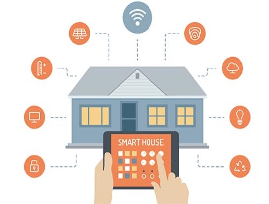
IOT (Internet of things) based home automation systems mainly focus on controlling the home electronic devices through internet whether you are outside or inside your home. Home automation provides an individual the ability to remotely or automatically control things in  the home. A home appliance is a device or instrument designed to perform a specific function, especially an electrical device, such as lights, fan, television, refrigerator, etc for household use.

Automation is today’s fact, where things are being controlled automatically, usually the basic tasks of turning on/off certain devices and beyond, either remotely or in close proximity. Automation lowers the human judgment to the lowest degree possible but does not completely eliminate it. The concept of remote management of household devices over the internet from anywhere, any time in the world today can be a reality. Assume a system where from the office desk, the user could view the status of the devices and decides to take control by tuning on the cooling system, say the air conditioner, and switches on or off some of the lights. This user could walk back home and only finds a very comfortable, pleasant home.

1.2 Problem statement

Many individuals are dependably moving from place to put because of business requests. A few people can spend two or three days from their home leaving all their family unit apparatuses with no sort of observing and control. A few gadgets are left connected to power attachments though others should be connected to and out of energy attachments at various interims relying upon the time. This requires a person to physically take care of each of the gadgets autonomously every once in a while. All such observing and control should be possible without fundamentally being around or inside the home. A few gadgets if not controlled appropriately devour a great deal of vitality which prompts additional consumption on power. In this way I propose to plan a web based home mechanization framework which will empower one to remotely deal with his/her machines from anyplace, at whatever time.

1.3 Objectives of the study

1.3.1 Main objective

To design an IOT based home automation system for controlling home appliances.

1.3.2 Specific objectives

  1. To examine and recognize the weakness of present home automation systems
  2. To implement IOT based home automation at lower cost
  3. To design a flexible IOT based wireless home automation system
  4. To simulate and test the designed system

1.3.3 Research questions

  1. How can home appliances be controlled remotely by means of the web?
  2. How energy efficiency can be achieved?
  3. How can a gadget’s status be changed remotely by means of the web?
  4. How can a Internet based home automation system be intended to settle the distinguished shortcomings?

1.4 Scope of the study

My area of interest is to control home appliances remotely using the internet. This project focuses on the controlling of a lights and a fan. With lights and a fan, switching on and off will be considered. Even we can connect any other electrical loads which require 220V A.C supply to run.

All the loads are connected to A.C mains through electromagnetic relays, which are controlled using a microcontroller. These loads are switched on and off as per the commands sent to the microcontroller by the user.

1.5 Justification

Today, a few people flee from their zones of living arrangement and now and again need to travel and avoid their homes for two or three days. Accordingly, there is no get to and control of the family unit machines left at home yet there is a need to monitor the status and conduct of a few apparatuses. For manual control, an individual ought to either always move forward and backward amongst home and work put or have a specialist for every one of the gadgets. Be that as it may, having a chaperon won’t not take care of the issue as by and large the gadgets are such a variety of and circulated to be proficiently, physically controlled by one individual. The machines might be circulated in a few rooms of the house which may require a person to move starting with one room then onto the next each other time attempting to screen and control such apparatuses. Such sort of control may end up being exceptionally frenzied.

On the off chance that a computerized framework is planned, it will decrease on the time, influence wastage and cash required for a man to take care of each of the gadgets at his/her home. With a specific end goal to have accommodation and diminishment in the additional costs brought about in controlling machines at home, paying little mind to whether one is around or far from his/her home, a remote control framework, if outlined can empower the client to consequently control such apparatuses. In this way there is a need to outline a computerization framework in order to mechanize the control of family unit apparatuses.

CHAPTER TWO: LITERATURE REVIEW

2.1   Home automation

2.1.1   What is Home Automation?

Home automation is the residential extension of building automation. It is the automation of the home, housework or household activity. Home automation using the Internet of things is the way that all of our devices and appliances will be networked together to provide us with a seamless control over all aspects of our home and more.

Home automation has been around from numerous decades as far as lighting and straightforward apparatus control, and just as of late has innovation gotten up to speed for the possibility of the interconnected world, permitting full control of your home from anyplace, to end up noticeably a reality. With home automation, you direct how a gadget ought to respond, when it ought to respond, and why it ought to respond. You set the calendar and the rest is mechanized and based off of your own inclinations therefore giving comfort, control, cash investment funds, and a general more brilliant home. Home automation can likewise aware you of occasions that you might need to think about immediately while you are gone like water holes and sudden access to your home, or any piece of it. Whenever, you can get your iPhone, Android gadget or other remote control and change the settings in your home as fancied. In the course of recent decades many organizations have entered the home automation segment.

http://www.safewise.com/blog/wp-content/uploads/smart-home.jpg


2.1.2   Convenience

Control and automate pretty much every gadget and machine inside your home whether you are at home or far away. We’ve all gotten used to controlling our TV from the lounge chair; simply hold up until you can diminish the lights also. Envision changing the temperature from your bed or controlling the volume of your entire house sound framework from any room. Or, on the other hand envision the divider/roof radiator in your restroom going ahead naturally on nippy mornings five minutes before your wake up timer goes off with the goal that it is warm when you enter. Many Smart home items likewise spare vitality which we as a whole concur that is a decent accommodation.

interactive-house

2.1.3   Safety

Continuously on protect and primed and ready, home automation gives security, defending your home. From a surveillance camera’s peering eye to a water sensor that will caution you of a conceivable exorbitant release, a computerized home holds your property under reconnaissance so you can respond immediately. We’re altogether used to opening the carport entryway from the auto, yet you’ll be astonished how much more secure you’ll feel returning home to a lit home and not withstanding turning on more lights from your key coxcomb remote upon your landing. Envision your home sending you an email if there is movement where there shouldn’t be any. Or, on the other hand you can have your security framework call you if there is an alert, which may incorporate your regular security caution or even a low or high temperature or water in the pantry or storm cellar.

2.1.4   Energy Savings

Energy saving is considered as one of the most important issue affects the consumers, power system quality and the global environment. The high energy demanded by home appliances, air conditioning and lighting makes homes to be considered as one of the most critical area for the impact of energy consumption. IOT based home automation technology is a good choice for people not only care about security, comfort but energy saving as well. It minimizes the domestic energy waste and can be adapted according to the user habits.

2.2    Internet & IoT

The Internet is the global system of interconnected computer networks that use the Internet protocol suite (TCP/IP) to link devices worldwide. It is a network of networks that consists of private, public, academic, business, and government networks of local to global scope, linked by a broad array of electronic, wireless, and optical networking technologies. The Internet carries an extensive range of information resources and services, such as the inter-linked hypertext documents and applications of the World Wide Web (WWW), electronic mailtelephony, and peer-to-peer networks for file sharing. The Internet is now widely used as a connectivity tool for educational, commercial, and personal applications. The Internet is an exciting portal that makes it possible for users to access virtually an infinite supply of information.

http://rvtechnologies.co.in/images/services_image/WMa8dXEbVTVZOuM.jpg

The Internet of things (IoT) is the inter-networking of physical devices, vehicles (also referred to as “connected devices” and “smart devices“), buildings, and other items embedded with electronicssoftwaresensors, actuators, and network connectivity that enable these objects to collect and exchange data. The IoT allows objects to be sensed or controlled remotely across existing network infrastructure, creating opportunities for more direct integration of the physical world into computer-based systems, and resulting in improved efficiency, accuracy and economic benefit in addition to reduced human intervention. When IoT is augmented with sensors and actuators, the technology becomes an instance of the more general class of cyber-physical systems, which also encompasses technologies such as smart gridsvirtual power plantssmart homesintelligent transportation and smart cities. Each thing is uniquely identifiable through its embedded computing system but is able to interoperate within the existing Internet infrastructure.

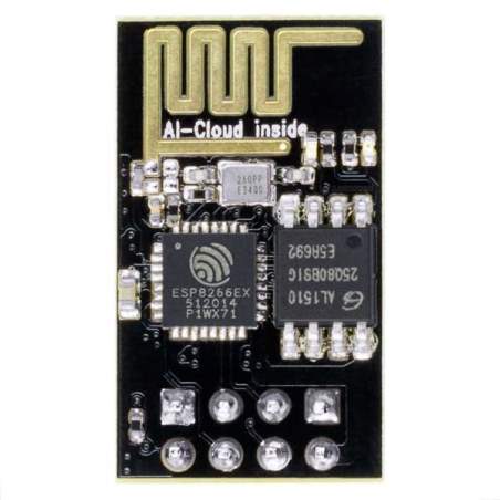
2.3   ESP8266 Wi-Fi module


2.3.1   Technical Overview

ESP Systems’ Smart Connectivity Platform (ESCP) is a set of high performance, high integration wireless SOCs, designed for space and power constrained mobile platform designers. It provides unsurpassed ability to embed WiFi capabilities within other systems, or to function as a standalone application, with the lowest cost, and minimal space requirement.

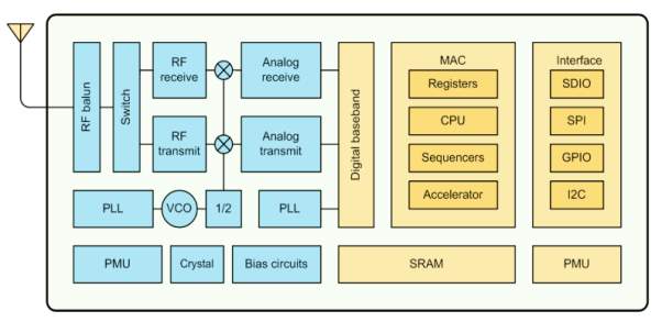
ESP8266 offers a complete and self-contained WiFi networking solution. It can be used to host the application or to offload WiFi networking functions from another application processor. When ESP8266 hosts the application, it boots up directly from an external flash. In has integrated cache to improve the performance of the system in such applications. Alternately, serving as a WiFi adapter, wireless internet access can be added to any micro controller based design with simple connectivity (SPI/SDIO or I2C/UART interface). ESP8266 is among the most integrated WiFi chip in the industry. It integrates the antenna switches, RF balun, power amplifier, low noise receive amplifier, filters, power management modules, it requires minimal external circuitry, and the entire solution, including front-end module, is designed to occupy minimal PCB area. ESP8266 also integrates an enhanced version of Tensilica’s L106 Diamond series 32-bit processor, with on-chip SRAM, besides the WiFi functionalities. ESP8266 is often integrated with external sensors and other application specific devices through its GPIOs; sample codes for such applications are provided in the software development kit (SDK).

ESP Systems’ Smart Connectivity Platform (ESCP) systems demonstrates sophisticated system-level features include fast sleep/wake context switching for energy-efficient VoIP, adaptive radio biasing for low-power operation, advance signal processing, and spur cancellation and radio co-existence features for common cellular, Bluetooth, DDR, LVDS, LCD interference mitigation.

2.3.2   Features

  • 802.11 b/g/n
  • Integrated low power 32-bit MCU
  • Integrated 10-bit ADC
  • Supports antenna diversity
  • WiFi 2.4 GHz, support WPA/WPA2
  • Standby power consumption of < 1.0mW (DTIM3)
  • Integrated TCP/IP protocol stack
  • Integrated TR switch, balun, LNA, power amplifier and matching network
  • Integrated PLL, regulators, and power management units
  • +20 dBm output power in 802.11b mode
  • Operating temperature range -40C ~ 125C
  • FCC, CE, TELEC, WiFi Alliance, and SRRC certified
  • Support STA/AP/STA+AP operation modes
  • Support Smart Link Function for both Android and iOS devices
  • SDIO 2.0, (H) SPI, UART, I2C, I2S, IR Remote Control, PWM, GPIO
  • STBC, 1×1 MIMO, 2×1 MIMO
  • A-MPDU & A-MSDU aggregation & 0.4s guard interval
  • Deep sleep power <10uA, Power down leakage current < 5uA
  • Wake up and transmit packets in < 2ms

2.3.3 Parameters

Categories Items Values
WiFi Paramters Certificates FCC/CE/TELEC/SRRC
WiFi Protocles 802.11 b/g/n
Frequency Range 2.4G-2.5G (2400M-2483.5M)
Tx Power 802.11 b: +20 dBm
802.11 g: +17 dBm
802.11 n: +14 dBm
Rx Sensitivity 802.11 b: -91 dbm (11 Mbps)
802.11 g: -75 dbm (54 Mbps)
802.11 n: -72 dbm (MCS7)
Types of Antenna PCB Trace, External, IPEX Connector, Ceramic Chip
Hardware Paramaters Peripheral Bus UART/SDIO/SPI/I2C/I2S/IR Remote Control
GPIO/PWM
Operating Voltage 3.0~3.6V
Operating Current Average value: 80mA
Operating Temperature Range -40°~125°
Ambient Temperature Range Normal temperature
Package Size 5x5mm
External Interface N/A
Software Parameters WiFi mode station/softAP/SoftAP+station
Security WPA/WPA2
Encryption WEP/TKIP/AES
Firmware Upgrade UART Download / OTA (via network)
Software Development Supports Cloud Server Development / SDK for custom firmware development
Network Protocols IPv4, TCP/UDP/HTTP/FTP
User Configuration AT Instruction Set, Cloud Server, Android/ iOS App

2.3.4   Ultra Low Power Technology

ESP8266 has been intended for portable, wearable hardware and Internet of Things applications with the point of accomplishing the most reduced power utilization with a mix of a few exclusive procedures. The power sparing design works predominantly in 3 modes: dynamic mode, rest mode and profound rest mode. By utilizing advance power administration methods and rationale to shut down capacities not required and to control exchanging amongst rest and dynamic modes, ESP8266 expends about than 60uA in profound rest mode (with RTC clock as yet running) and under 1.0mA (DTIM=3) or under 0.5mA (DTIM=10) to remain associated with the get to point. At the point when in rest mode, just the aligned continuous clock and guard dog stays dynamic. The constant clock can be modified to awaken the ESP8266 at any required interim. The ESP8266 can be customized to wake up when a predetermined condition is distinguished. This negligible wake-up time highlight of the ESP8266 can be used by cell phone SOCs, permitting them to stay in the low-control standby mode until WiFi is required. Keeping in mind the end goal to fulfill the power request of portable and wearable gadgets, ESP8266 can be customized to diminish the yield energy of the PA to fit different application profiles, by exchanging off range for power utilization.

2.2.5   Major Applications

Major fields of ESP8266EX applications to Internet-of-Things include:

  • Home Appliances
  • Home Automation
  • IP Cameras
  • Sensor Networks
  • Wearable Electronics
  • WiFi Location-aware Devices
  • Security ID Tags
  • Industrial Wireless Control
  • Baby Monitors
  • WiFi Position System Beacons
  • Smart Plug and lights

2.2.6   Pin Description

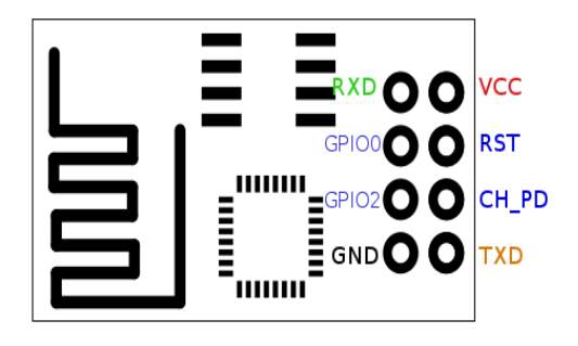
  1. RXD – UART Receive during flash programming. Serial data is received through this pin.
  2. GPIO0 – General purpose Input/Output pin0. This pin is made low during flash operation.
  3. GPIO2 – General Purpose Input/Output pin2.
  4. GND – Ground terminal for power supply.
  5. TXD – UART Receive during flash programming. Serial data is transmitted through this pin.
  6. CH_PD – Active high chip enable pin. High: On, chip works properly; Low: Off, small current.
  7. RST – Active low external reset pin.
  8. VCC – Power supply (3.0V-3.6V).

2.2.7   Microcontroller unit

ESP8266EX is embedded with Tensilica L106 32-bit micro controller (MCU), which features extra low power consumption and 16-bit RSIC. The CPU clock speed is 80MHz. It can also reach a maximum value of 160MHz. Real Time Operation System (RTOS) is enabled. Currently, only 20% of MIPS has been occupied by the WiFi stack, the rest can all be used for user application programming and development. The following interfaces can be used to connect to the MCU embedded in ESP8266EX:

  • Programmable RAM/ROM interfaces (iBus), which can be connected with memory controller, and can also be used to visit external flash.
  • Data RAM interface (dBus), which can connect with memory controller.
  • AHB interface can be used to visit the register.

2.2.8 Firmware & Software Development Kit

The application and firmware is executed in on-chip ROM and SRAM, which loads the instructions during wake-up, through the SDIO interface, from the external flash. The firmware implements TCP/IP, the full 802.11 b/g/n/e/i WLAN MAC protocol and WiFi Direct specification. It supports not only basic service set (BSS) operations under the distributed control function (DCF) but also P2P group operation compliant with the latest WiFi P2P protocol. Low level protocol functions are handled automatically by ESP8266:

  • RTS/CTS
  • acknowledgement
  • fragmentation and defragmentation
  • aggregation
  • frame encapsulation (802.11h/RFC 1042)
  • automatic beacon monitoring / scanning, and
  • P2P WiFi direct

Passive or active scanning, as well as P2P discovery procedure is performed autonomously once initiated by the appropriate command. Power management is handled with minimum host interaction to minimize active duty period. The SDK includes the following library functions:

  • 802.11 b/g/n/d/e/i/k/r support
  • WiFi Direct (P2P) support
  • P2P Discovery, P2P Group Owner mode, P2P Power Management.
  • Infrastructure BSS Station mode / P2P mode / softAP mode support.
  • Hardware accelerators for CCMP (CBC-MAC, counter mode), TKIP (MIC, RC4), WAPI (SMS4), WEP (RC4), CRC.
  • WPA/WPA2 PSK, and WPS driver
  • Additional 802.11i security features such as pre-authentication, and TSN.
  • Open Interface for various upper layer authentication schemes over EAP such as TLS, PEAP, LEAP, SIM, AKA, or customer specific.
  • 802.11n support (2.4GHz)
  • Supports MIMO 1×1 and 2×1, STBC, A-MPDU and A-MSDU aggregation and 0.4μs guard interval.
  • WMM power save U-APSD
  • Multiple queue management to fully utilize traffic prioritization defined by 802.11e standard.
  • UMA compliant and certified
  • 802.1h/RFC1042 frame encapsulation
  • Scattered DMA for optimal CPU off load on Zero Copy data transfer operations.
  • Antenna diversity and selection (software managed hardware).
  • Clock/power gating combined with 802.11-compliant power management dynamically adapted to current connection condition providing minimal power consumption.

2.2.9   AT commands

ESP8266, in it’s default configuration, boots up into the serial modem mode. In this mode you can communicate with it using a set of AT commands. Historically AT commands are based on the Hayes Command Set and these are no different. AT command set is divided into: Basic AT commands, Wi-Fi AT commands, TCP/IP AT commands. ESP8266 expects <CR> and <LF> or Carriage Return and Line Feed at the end of each command, but just<CR> seems to work too.

a.   Command description

Each command can have up to 4 variants changing the function of it. You can chose between them by appending one of four possible values to the end of the root command itself. These four appendices can have the following values “”,=<parameter|[parameters]>,”?”,=?

Type Example Description
Test AT + < x > =? Query the Set command or internal parameters and its

range values.

Query AT + < x >? Returns the current value of the parameter.
Set AT + < x > = < x > Set the value of user-defined parameters in commands and run.
Execute AT + < x > Runs commands with no user-defined parameters.

Notes:

1. Not all AT commands support all the above mentioned four variations.

2. [] = default value, not required or may not appear

3. String values require double quotation marks, for example:

AT+CWSAP=”ESP756290″, “21030826”, 1, 4

4. Default Baud rate = 115200

5. AT commands have to be capitalized, and must terminate with “/r/n”. Terminal programs must be set up accordingly (refer to screenshot below).

b.   Basic AT Commands

AT – Test AT startup

Variant Command Response Function
Execute AT OK Test if AT system works correctly

AT+RST – Restart module

Variant Command Response Function
Execute AT+RST OK Reset the module

AT+GMR – View version info

Variant Command Response Function
Execute AT+GMR version, OK Print firmware version

AT+GSLP – Enter deep-sleep mode

Variant Command Response Function
set AT+GSLP=time Time OK Enter deep sleep mode for time milli seconds

ATE – Enable / Disable echo

Variant Command Response Function
Execute ATE0 OK Disable echo (Doesn’t send back received command)
Execute ATE1 OK Enable echo (Sends back received command before response)

AT+CWMODE – WIFI mode( station, AP, station + AP)

Variant Command Response Function
Test AT+CWMODE=? +CWMODE:(1-3) OK List valid modes
Query AT+CWMODE? +CWMODE: mode OK Query AP’s info which is connecting by ESP8266.
Execute AT+CWMODE= mode OK Set AP’s info which will be connecting by ESP8266.


b.   WiFi related AT Commands

AT+CWJAP – Connect to AP

Variant Command Response Function
Query AT+CWJAP? +CWJAP: ssid OK Prints the SSID of Access Point ESP8266 is connected to.
Execute AT+CWJAP= ssid, pwd OK Commands ESP8266 to connect a SSID with supplied password.
Example:

AT+CWJAP=”my-test-wifi”,”1234test”

Example:
AT+CWJAP?:+CWJAP:”my-test-wifi”

AT+CWLAP – Lists available APs

Variant Command Response Function
Set AT+CWLAP=ssid,mac,ch +CWLAP:ecn,ssid,rssi,macOK Search available APs with specific conditions.
Execute AT+CWLAP AT+CWLAP:ecn,ssid,rssi,macOK Lists available Access Points.
Parameters:
  • ecn:
    • 0 = OPEN
    • 1 = WEP
    • 2 = WPA_PSK
    • 3 = WPA2_PSK
    • 4 = WPA_WPA2_PSK
  • ssid: String, SSID of AP
  • rssi: signal strength
  • mac: String, MAC address
Note:

On ESP-01 I have had no luck with the set version of this command (AT+CWLAP=…). If you know what it does please let me know.

Example AT+CWLAP:

+CWLAP:(3,”CVBJB”,-71,”f8:e4:fb:5b:a9:5a”,1)

+CWLAP:(3,”HT_00d02d638ac3″,-90,”04:f0:21:0f:1f:61″,1)

+CWLAP:(3,”CLDRM”,-69,”22:c9:d0:1a:f6:54″,1)

+CWLAP:(2,”AllSaints”,-88,”c4:01:7c:3b:08:48″,1)

+CWLAP:(0,”AllSaints-Guest”,-83,”c4:01:7c:7b:08:48″,1)

AT+CWQAP – Disconnect from AP

Variant Command Response Function
Execute AT+CWQAP OK Disconnect ESP8266 from the AP is currently connected to.
Note:

After running this command, if you run AT+CWJAP? it still shows the AP you were connected to before.

AT+CWSAP – Configuration of softAP mode

Variant Command Response Function
Query AT+CWSAP? +CWSAP:ssid,pwd,ch,ecnOK Query configuration of ESP8266 softAP mode.
Set AT+CWSAP=ssid,pwd,ch,ecn OK Set configuration of softAP mode.
Parameters:
  • ssid: String, ESP8266’s softAP SSID
  • pwd: String, Password, no longer than 64 characters
  • ch: channel id
  • ecn:
    • 0 = OPEN
    • 2 = WPA_PSK
    • 3 = WPA2_PSK
    • 4 = WPA_WPA2_PSK

Example
AT+CWSAP=”esp_123″,”1234test”,5,3
AT+CWSAP? => +CWSAP:”esp_123″,”1234test”,5,3

AT+CWLIF – List clients connected to ESP8266 softAP

Variant Command Response Function
Execute AT+CWLIF [ip,other] OK List information on of connected clients.
Parameters:

ip: IP address of a client connected to the ESP8266 softAP other: Other info, look at example. I don’t know what it means yet.

Example (ESP-01):

AT+CWLIF

192.168.4.100,3fff50b4:3fff50ba:3fff50c0:3fff50c6:3fff50cc:3fff50d2

OK

AT+CWDHCP – Enable/Disable DHCP

Variant Command Response Function
Set AT+CWDHCP=mode,en OK Enable or disable DHCP for selected mode
Parameters:
  • mode:
    • 0 : set ESP8266 as a softAP
    • 1 : set ESP8266 as a station
    • 2 : set both ESP8266 to both softAP and a station
  • en:
    • 0 : Enable DHCP
    • 1 : Disable DHCP

AT+CIPSTAMAC – Set MAC address of ESP8266 station

Variant Command Response Function
Query AT+CIPSTAMAC? +CIPSTAMAC:macOK Print current MAC ESP8266’s address.
Execute AT+CIPSTAMAC=mac OK Set ESP8266’s MAC address.
Parameters:
  • mac: String, MAC address of the ESP8266 station.
Example:

AT+CIPSTAMAC=”18:aa:35:97:d4:7b”

AT+CIPAPMAC – Set MAC address of ESP8266 softAP

Variant Command Response Function
Query AT+CIPAPMAC? +CIPAPMAC:macOK Get MAC address of ESP8266 softAP.
Execute AT+CIPAPMAC=mac OK Set mac of ESP8266 softAP.
Parameters:
  • mac: String, MAC address of the ESP8266 softAP.
Example:

AT+CIPAPMAC=”2c:aa:35:97:d4:7b”

AT+CIPSTA – Set IP address of ESP8266 station

Variant Command Response Function
Query AT+CIPSTA? +CIPSTA:ipOK Get IP address of ESP8266 station.
Execute AT+CIPSTA=ip OK Set ip addr of ESP8266 station.
Parameters:
  • ip: String, ip address of the ESP8266 station.
Example:

AT+CIPSTA=”192.168.101.108”

AT+CIPAP – Set ip address of ESP8266 softAP

Variant Command Response Function
Query AT+CIPAP? +CIPAP:ip OK Get ip address of ESP8266 softAP.
Execute AT+CIPAP=ip OK Set ip addr of ESP8266 softAP.
Parameters:
  • ip: String, ip address of ESP8266 softAP.
Example:

AT+CIPAP=”192.168.5.1″

c.   TCP/IP related AT commands

AT+CIPSTATUS – Information about connection

Variant Command Response Function
Test AT+CIPSTATUS=? OK
Execute AT+CIPSTATUS STATUS:status+CIPSTATUS:id,type,addr,port,tetypeOK Get information about connection.
Parameters:
  • status:
    • 2: Got IP
    • 3: Connected
    • 4: Disconnected
  • id: id of the connection (0~4), for multi-connect
  • type: String, “TCP” or “UDP”
  • addr: String, IP address.
  • port: port number
  • tetype:
    • 0 = ESP8266 runs as a client
    • 1 = ESP8266 runs as a server
Note:

On ESP-01 this command returns STATUS:1 instead (no extra info, but status changes) On 0018000902-AI03 this command returns STATUS:2 instead (no extra info, but status changes)

AT+CIPSTART – Establish TCP connection or register UDP port and start a connection

Variant Command Response Function
Set AT+CIPSTART=type,addr,port OK Start a connection as client. (Single connection mode)
Set AT+CIPSTART=id,type,addr,port OK Start a connection as client. (Multiple connection mode)
Test AT+CIPSTART=? [+CIPSTART:(id)(“type”),(“ip address”),(port)] OK List possible command variations)
Parameters:
  • id: 0-4, id of connection
  • type: String, “TCP” or “UDP”
  • addr: String, remote IP
  • port: String, remote port

AT+CIPSEND – Send data

Variant Command Response Function
Test AT+CIPSEND=? OK
Set AT+CIPSEND=length SEND OK Set length of the data that will be sent. For normal send (single connection).
Set AT+CIPSEND=id,length SEND OK Set length of the data that will be sent. For normal send (multiple connection).
Execute AT+CIPSEND Send data. For unvarnished transmission mode.
Parameters:
  • id: ID no. of transmit connection
  • length: data length, MAX 2048 bytes

AT+CIPCLOSE – Close TCP or UDP connection

Variant Command Response Function
Test AT+CIPCLOSE=? OK
Set AT+CIPCLOSE=id OK Close TCP or UDP connection.For multiply connection mode
Execute AT+CIPCLOSE OK Close TCP or UDP connection.For single connection mode
Parameters:
  • id: ID no. of connection to close, when id=5, all connections will be closed.

AT+CIFSR – Get local IP address

Variant Command Response Function
Test AT+CIFSR=? OK
Execute AT+CIFSR +CIFSR:ip OK Get local IP address.
Parameters:
  • ip: IP address of the ESP8266 as an client.
Example AT+CIFSR:

10.101.10.134

AT+CIPMUX – Enable multiple connections or not

Variant Command Response Function
Set AT+CIPMUX=mode OK Enable / disable multiplex mode (up to 4 conenctions)
Query AT+CIPMUX? +CIPMUX:modeOK Print current multiplex mode.
Parameters:
  • mode:
    • 0: Single connection
    • 1: Multiple connections (MAX 4)
NOTE:

This mode can only be changed after all connections are disconnected. If server is started, reboot is required.

AT+CIPSERVER – Configure as server

Variant Command Response Function
Set AT+CIPSERVER=mode[,port] OK Configure ESP8266 as server
Parameters:
  • mode:
  • 0: Delete server (need to follow by restart)
  • 1: Create server
  • port: port number, default is 333
NOTE:
  1. Server can only be created when AT+CIPMUX=1
  2. Server monitor will automatically be created when Server is created.
  3. When a client is connected to the server, it will take up one connection,be gave an id.

AT+CIPMODE – Set transfer mode

Variant Command Response Function
Query AT+CIPMODE? +CIPMODE:modeOK Set transfer mode,normal or transparent transmission.
Set AT+CIPMODE=mode OK Set transfer mode,normal or transparent transmission.
Parameters:
  • mode:
  • 0: normal mode
  • 1: unvarnished transmission mode

AT+CIPSTO – Set server timeout

Variant Command Response Function
Query AT+CIPSTO? +CIPSTO:time Query server timeout.
Set AT+CIPSTO=time OK Set server timeout.
Parameters:
  • time: server timeout, range 0~7200 seconds

AT+CIUPDATE – update through network

Variant Command Response Function
Execute AT+CIUPDATE +CIPUPDATE:n OK Start update through network
Parameters:

-n:
– 1: found server
– 2: connect server
– 3: got edition
– 4: start update

Example:

AT+CIUPDATE

+CIUPDATE: 1

+CIUPDATE: 2

+CIUPDATE: 3

+CIUPDATE: 4

x02x8clx8elx8ex1cpx0cx8cxf2nnxeex00lx8cx8el`

x02x90x12x12nnlx8cl`x02x0ex02nrx8ex92x92nx0cx0c

x02x8cx92`x02`

xf2nx0cx0cx0cx9exe0bx82nlx8cx0cx8c

xf2nnxeex00x0cx8ex0elpxf2nxe0x10x02x0c

x0crx8cx9cx9cxe2xe0x0cx0cx0c

x0cbx0cnxe2|x02xecxeclx8cx0cbx8cxf2nn

…forever

+IPD – Receive network data

Variant Command Response Function
Execute +IPD,len:data Receive network data from single connection.
Execute +IPD,id,len:data Receive network data from multiple connection.
Parameters:
  • id: id no. of connection
  • len: data length
  • data: data received

2.4 Atmega 328P Microcontroller

http://www.homeautomationhub.com/sites/default/files/imagecache/product_full/328p.jpg

2.4.1   Overview

A microcontroller is an application specific integrated circuit (ASIC) that fetches and executes instructions based on input from some user program. These devices do not have a fixed function, but rather are controlled by software. Microcontroller is designed to govern the operation of embedded systems in motor vehicles, robots, office machines, complex medical devices, mobile radio transceivers, vending machines, home appliances, and various other devices. A typical microcontroller includes a processormemory, and peripherals. The simplest microcontrollers facilitate the operation of the electromechanical systems found in everyday convenience items. Originally, such use was confined to large machines such as furnaces and automobile engines to optimize efficiency and performance. In recent years, microcontrollers have found their way into common items such as ovens, refrigerators, toasters, clock radios, and lawn watering systems. Microcomputers are also common in office machines such as photocopiers, scannersfax machines, and printers.

The most sophisticated microcontrollers perform critical functions in aircraft, spacecraft, ocean-going vessels, life-support systems, and robots of all kinds. Medical technology offers especially promising future roles. For example, a microcontroller might regulate the operation of an artificial heart, artificial kidney, or other artificial body organ. Microcomputers can also function with prosthetic devices (artificial limbs). A few medical science futurists have suggested that mute patients might someday be able, in effect, to speak out loud by thinking of the words they want to utter, while a microcontroller governs the production of audio signals to drive an amplifier and loudspeaker. Today’s microcontrollers are much different from what it were in the initial stage, and the number of manufacturers are much more in count than it was a decade or two ago. At present some of the major manufacturers are Microchip (publication: PIC microcontrollers), Atmel (publication: AVR microcontrollers), Hitachi, Phillips, Maxim, NXP, Intel etc.  Our interest is upon ATmega328. It belongs to Atmel’s AVR series micro controller family.

The ATmega328P is a low-power CMOS 8-bit microcontroller based on the AVR enhanced RISC architecture. By executing powerful instructions in a single clock cycle, the ATmega328P achieves throughputs approaching 1 MIPS per MHz allowing the system designed to optimize power consumption versus processing speed. The high-performance Microchip pico Power 8-bit AVR RISC-based microcontroller combines 32KB ISP flash memory with read-while-write capabilities, 1024B EEPROM, 2KB SRAM, 23 general purpose I/O lines, 32 general purpose working registers, three flexible timer/counters with compare modes, internal and external interrupts, serial programmable USART, a byte oriented 2-wire serial interface, SPI serial port, a 6-channel 10-bit A/D converter (8-channels in TQFP and QFN/MLF packages), programmable watchdog timer with internal oscillator, and five software selectable power saving modes. The device operates between 1.8-5.5 volts.

2.4.2   Block Diagram


The Atmel AVR® core combines a rich instruction set with 32 general purpose working registers. All the 32 registers are directly connected to the Arithmetic Logic Unit (ALU), allowing two independent registers to be accessed in a single instruction executed in one clock cycle. The resulting architecture is more code efficient while achieving throughputs up to ten times faster than conventional CISC microcontrollers.

The ATmega328/P provides the following features: 32Kbytes of In-System Programmable Flash with Read-While-Write capabilities, 1Kbytes EEPROM, 2Kbytes SRAM, 23 general purpose I/O lines, 32 general purpose working registers, Real Time Counter (RTC), three flexible Timer/Counters with compare modes and PWM, 1 serial programmable USARTs , 1 byte-oriented 2-wire Serial Interface (I2C), a 6-channel 10-bit ADC (8 channels in TQFP and QFN/MLF packages) , a programmable Watchdog Timer with internal Oscillator, an SPI serial port, and six software selectable power saving modes.

The Idle mode stops the CPU while allowing the SRAM, Timer/Counters, SPI port, and interrupt system to continue functioning. The Power-down mode saves the register contents but freezes the Oscillator, disabling all other chip functions until the next interrupt or hardware reset. In Power-save mode, the asynchronous timer continues to run, allowing the user to maintain a timer base while the rest of the device is sleeping. The ADC Noise Reduction mode stops the CPU and all I/O modules except asynchronous timer and ADC to minimize switching noise during ADC conversions. In Standby mode, the crystal/resonator oscillator is running while the rest of the device is sleeping. This allows very fast start-up combined with low power consumption. In Extended Standby mode, both the main oscillator and the asynchronous timer continue to run.

Atmel offers the QTouch® library for embedding capacitive touch buttons, sliders and wheels functionality into AVR microcontrollers. The patented charge-transfer signal acquisition offers robust sensing and includes fully debounced reporting of touch keys and includes Adjacent Key Suppression® (AKS™) technology for unambiguous detection of key events. The easy-to-use QTouch Suite toolchain allows you to explore, develop and debug your own touch applications.

The device is manufactured using Atmel’s high density non-volatile memory technology. The On-chip ISP Flash allows the program memory to be reprogrammed In-System through an SPI serial interface, by a conventional nonvolatile memory programmer, or by an On-chip Boot program running on the AVR core. The Boot program can use any interface to download the application program in the Application Flash memory. Software in the Boot Flash section will continue to run while the Application Flash section is updated, providing true Read-While-Write operation. By combining an 8-bit RISC CPU with In-System Self-Programmable Flash on a monolithic chip, the Atmel ATmega328/P is a powerful microcontroller that provides a highly flexible and cost effective solution to many embedded control applications. The ATmega328/P is supported with a full suite of program and system development tools including: C Compilers, Macro Assemblers, Program Debugger/Simulators, In-Circuit Emulators, and Evaluation kits.

2.4.3   Features

High Performance, Low Power Atmel®AVR® 8-Bit Microcontroller Family

  • Advanced RISC Architecture
  • 131 Powerful Instructions
  • Most Single Clock Cycle Execution
  • 32 x 8 General Purpose Working Registers
  • Fully Static Operation
  • Up to 20 MIPS Throughput at 20MHz
  • On-chip 2-cycle Multiplier
  • High Endurance Non-volatile Memory Segments
  • 32KBytes of In-System Self-Programmable Flash program Memory
  • 1KBytes EEPROM
  • 2KBytes Internal SRAM
  • Write/Erase Cycles: 10,000 Flash/100,000 EEPROM
  • Data Retention: 20 years at 85°C/100 years at 25°C(1)
  • Optional Boot Code Section with Independent Lock Bits
  • In-System Programming by On-chip Boot Program
  • True Read-While-Write Operation
    • Programming Lock for Software Security
    • Atmel® QTouch® Library Support
    • Capacitive Touch Buttons, Sliders and Wheels
    • QTouch and QMatrix® Acquisition
    • Up to 64 sense channels
    • Peripheral Features
    • Two 8-bit Timer/Counters with Separate Prescaler and Compare Mode
    • One 16-bit Timer/Counter with Separate Prescaler, Compare Mode, and Capture Mode
    • Real Time Counter with Separate Oscillator
    • Six PWM Channels
    • 8-channel 10-bit ADC in TQFP and QFN/MLF package
    • Temperature Measurement
  • 6-channel 10-bit ADC in PDIP Package
  • Temperature Measurement
  • Two Master/Slave SPI Serial Interface
  • One Programmable Serial USART
  • One Byte-oriented 2-wire Serial Interface (Philips I2C compatible)
  • Programmable Watchdog Timer with Separate On-chip Oscillator
  • One On-chip Analog Comparator
  • Interrupt and Wake-up on Pin Change
  • Special Microcontroller Features
    • Power-on Reset and Programmable Brown-out Detection
    • Internal Calibrated Oscillator
    • External and Internal Interrupt Sources
    • Six Sleep Modes: Idle, ADC Noise Reduction, Power-save, Power-down, Standby, and Extended Standby
    • I/O and Packages
    • 23 Programmable I/O Lines
    • 28-pin PDIP, 32-lead TQFP, 28-pad QFN/MLF and 32-pad QFN/MLF
  • Operating Voltage:
  • 1.8 – 5.5V
  • Temperature Range:
  • -40°C to 105°C
  • Speed Grade:
  • 0 – 4MHz @ 1.8 – 5.5V
  • 0 – 10MHz @ 2.7 – 5.5V
  • 0 – 20MHz @ 4.5 – 5.5V
  • Power Consumption at 1MHz, 1.8V, 25°C
  • Active Mode: 0.2mA
  • Power-down Mode: 0.1μA

      Power-save Mode: 0.75μA (Including 32kHz RTC)

2.2.4 Pin Description

1. VCC

Digital supply voltage.

2. GND

Ground.

3. Port B (PB[7:0]) XTAL1/XTAL2/TOSC1/TOSC2

Port B is an 8-bit bi-directional I/O port with internal pull-up resistors (selected for each bit). The Port B output buffers have symmetrical drive characteristics with both high sink and source capability. As inputs, Port B pins that are externally pulled low will source current if the pull-up resistors are activated. The Port B pins are tri-stated when a reset condition becomes active, even if the clock is not running. If the Internal Calibrated RC Oscillator is used as chip clock source, PB[7:6] is used as TOSC[2:1] input for the Asynchronous Timer/Counter2 if the AS2 bit in ASSR is set.

4. Port C (PC[5:0])

Port C is a 7-bit bi-directional I/O port with internal pull-up resistors (selected for each bit). The PC[5:0] output buffers have symmetrical drive characteristics with both high sink and source capability. As inputs, Port C pins that are externally pulled low will source current if the pull-up resistors are activated. The Port C pins are tri-stated when a reset condition becomes active, even if the clock is not running.

5. PC6/RESET

If the RSTDISBL Fuse is programmed, PC6 is used as an I/O pin. Note that the electrical characteristics of PC6 differ from those of the other pins of Port C. If the RSTDISBL Fuse is unprogrammed, PC6 is used as a Reset input. A low level on this pin for longer than the minimum pulse length will generate a Reset, even if the clock is not running.

6. Port D (PD[7:0])

Port D is an 8-bit bi-directional I/O port with internal pull-up resistors (selected for each bit). The Port D output buffers have symmetrical drive characteristics with both high sink and source capability. As inputs, Port D pins that are externally pulled low will source current if the pull-up resistors are activated. The Port D pins are tri-stated when a reset condition becomes active, even if the clock is not running.

7. AVCC

AVCC is the supply voltage pin for the A/D Converter, PC[3:0], and PE[3:2]. It should be externally connected to VCC, even if the ADC is not used. If the ADC is used, it should be connected to VCC through a low-pass filter. Note that PC[6:4] use digital supply voltage, VCC.

8. AREF

AREF is the analog reference pin for the A/D Converter.

9. ADC[7:6] (TQFP and VFQFN Package Only)

In the TQFP and VFQFN package, ADC[7:6] serve as analog inputs to the A/D converter. These pins are powered from the analog supply and serve as 10-bit ADC channels.

2.5    Liquid Crystal Display (LCD)

LCD (Liquid Crystal Display) screen is an electronic display module and find a wide range of applications. A 16×2 LCD display is very basic module and is very commonly used in various devices and circuits. These modules are preferred over seven segments and other multi segment LEDs. The reasons being: LCDs are economical; easily programmable; have no limitation of displaying special & even custom characters (unlike in seven segments), animations and so on.

A 16×2 LCD means it can display 16 characters per line and there are 2 such lines. In this LCD each character is displayed in 5×7 pixel matrix. This LCD has two registers, namely, Command and Data. The command register stores the command instructions given to the LCD. A command is an instruction given to LCD to do a predefined task like initializing it, clearing its screen, setting the cursor position, controlling display etc. The data register stores the data to be displayed on the LCD. The data is the ASCII value of the character to be displayed on the LCD.

2.5.1   Pin Description

http://circuits4you.com/wp-content/uploads/2016/05/lcd-16x2-pinout-300x196.png

 Pin No  Function  Name
1 Ground (0V) Ground
2 Supply voltage; 5V (4.7V – 5.3V)  Vcc
3 Contrast adjustment through a variable resistor  VEE
4 Selects command register when low; and data register when high Register Select
5 Low to write to the register; High to read from the register Read/write
6 Sends data to data pins when a high to low pulse is given Enable
7 8-bit data pins DB0
8 DB1
9 DB2
10 DB3
11 DB4
12 DB5
13 DB6
14 DB7
15 Backlight VCC (5V) Led+
16 Backlight Ground (0V) Led-

RS (Register select): A 16X2 LCD has two registers, namely, command and data. The register select is used to switch from one register to other. RS=0 for command register, whereas RS=1 for data register.

Command Register: The command register stores the command instructions given to the LCD. A command is an instruction given to LCD to do a predefined task like initializing it, clearing its screen, setting the cursor position, controlling display etc. Processing for commands happen in the command register.

Data Register:  The data register stores the data to be displayed on the LCD. The data is the ASCII value of the character to be displayed on the LCD. When we send data to LCD it goes to the data register and is processed there. When RS=1, data register is selected.

2.5.2   Working

LCD shows, each character is in a 5×8 framework. Where 5 are the number of rows and 8 is the number of columns. Here is a straight forward case on the most proficient method to make letter “b” in CG-RAM. The Array for producing “b” is char b[7]={0x10,0x10,0x16,0x19,0x11,0x11,0x1E}; That is,

  • Send address where you want to create character.
  • Now create your character at this address. Send the ‘b’ character array values defined above one by one to the data register of LCD.
  • To print the generated character at 0x40. Send command 0 to command register of LCD. The table below would explain this more clearly

2.6    Relay Driver ULN2003

https://electrosome.com/wp-content/uploads/2013/02/ULN2003.jpg


2.6.1   Overview

ULN2003 is a high voltage and high current Darlington array IC. It contains seven open collector darlington pairs with common emitters. A darlington pair is an arrangement of two bipolar transistors.

ULN2003 belongs to the family of ULN200X series of ICs. Different versions of this family interface to different logic families. ULN2003 is for 5V TTL, CMOS logic devices. These ICs are used when driving a wide range of loads and are used as relay drivers, display drivers, line drivers etc. ULN2003 is also commonly used while driving Stepper Motors. Refer Stepper Motor interfacing using ULN2003.

Each channel or darlington pair in ULN2003 is rated at 500mA and can survive peak current of 600mA. The inputs and outputs are given opposite to each other in the pin layout. Each driver also contains a suppression diode to scatter voltage spikes while driving inductive loads. The schematic for each driver is given below:

2.6.2   Features

  • High-Voltage Outputs: 50 V
  • 500-mA-Rated Collector Current (Single Output)
  • Inputs Compatible With Various Types of Logic
  • Relay-Driver Applications
  • Output Clamp Diodes

2.6.3   Pin Description

http://www.edgefxkits.com/blog/wp-content/uploads/Relay-Driver-IC-uln2003.jpg

PIN I/O DESCRIPTION
NAME NO.
1B 1 I Channel 1 through 7 Darlington base input
2B 2
3B 3
4B 4
5B 5
6B 6
7B 7
1C 16 O Channel 1 through 7 Darlington collector output
2C 15
3C 14
4C 13
5C 12
6C 11
7C 10
COM 9 Common cathode node for flyback diodes (required for inductive loads)
E 8 Common emitter shared by all channels (typically tied to ground)

I = Input, O = Output


2.6.4   Applications

  • Stepper and DC Brushed Motor Drivers
  • Logic Buffers
  • Lamp Drivers
  • Line Drivers
  • Relay Drivers
  • Display Drivers (LED and Gas Discharge)

2.7    Relays


2.7.1   Overview

The term Relay for the most part alludes to a gadget that gives an electrical association between at least two indicates accordingly the use of a control flag. The most well-known and generally utilized kind of electrical hand-off is the electromechanical transfer or EMR. The most essential control of any gear is the capacity to turn it “ON” and “OFF”. The most straightforward approach to do this is utilizing changes to intrude on the electrical supply. In spite of the fact that switches can be utilized to control something, they have their impediments. The greatest one is that they must be (physically) turned “ON” or “OFF”. Additionally, they are moderately extensive, moderate and just switch little electrical streams.

Electrical Relays in any case, are fundamentally electrically worked switches that come in many shapes, sizes and power appraisals reasonable for a wide range of uses. Transfers can likewise have single or numerous contacts inside a solitary bundle with the bigger power transfers utilized for mains voltage or high current exchanging applications being called “Contactors”.

Electrical transfers we are quite recently worried with the key working standards of “light obligation” electromechanical transfers we can use in engine control or automated circuits. Such transfers are utilized as a part of general electrical and electronic control or exchanging circuits either mounted specifically onto PCB sheets or associated unsupported and in which the heap streams are typically divisions of an ampere up to 20+ amperes.

The hand-off circuits are normal in Electronics applications. As their name suggests, electromechanical transfers are electro-attractive gadgets that change over an attractive flux created by the use of a low voltage electrical control flag either AC or DC over the hand-off terminals, into a pulling mechanical constrain which works the electrical contacts inside the hand-off. The most widely recognized type of electromechanical hand-off comprises of a stimulating curl called the “essential circuit” twisted around a penetrable iron center.

This iron center has both a settled bit called the burden, and a moveable spring stacked part called the armature, that finishes the attractive field circuit by shutting the air crevice between the settled electrical curl and the moveable armature. The armature is pivoted or rotated permitting it to uninhibitedly move inside the created attractive field shutting the electrical contacts that are joined to it. Associated between the burden and armature is ordinarily a spring (or springs) for the arrival stroke to “reset” the contacts back to their underlying rest position when the hand-off curl is in the “de-empowered” condition, i.e. turned “OFF”.

2.7.2   Electromechanical Relay Construction

Electromechanical Relay

In our straightforward hand-off above, we have two arrangements of electrically conductive contacts. Transfers might be “Ordinarily Open”, or “Regularly Closed”. One sets of contacts are classed as Normally Open, (NO) or make contacts and another set which are classed as Normally Closed, (NC) or break contacts. In the ordinarily vacant position, the contacts are shut just when the field current is “ON” and the switch contacts are pulled towards the inductive curl.

In the typically shut position, the contacts are for all time shut when the field current is “OFF” as the change contacts come back to their ordinary position. These terms Normally Open, Normally Closed or Make and Break Contacts allude to the condition of the electrical contacts when the transfer curl is “de-stimulated”, i.e, no supply voltage associated with the hand-off loop. Contact components might be of single or twofold represent the moment of truth plans. A case of this game plan is given beneath.

electrical relay contact tips

The transfers contacts are electrically conductive bits of metal which touch together finishing a circuit and permit the circuit current to stream, much the same as a switch. At the point when the contacts are open the resistance between the contacts is high in the Mega-Ohms, creating an open circuit condition and no circuit current streams.

At the point when the contacts are shut the contact resistance ought to be zero, a short out, yet this is not generally the situation. All transfer contacts have a specific measure of “contact resistance” when they are shut and this is known as the “On-Resistance”, like FET’s. With another hand-off and contacts this ON-resistance will be little, by and large under 0.2ω’s on account of the tips are new and clean, however after some time the tip resistance will increment.

For instance: If the contacts are passing a heap current of say 10A, then the voltage drop over the contacts utilizing Ohms law is 0.2 x 10 = 2 volts, which if the supply voltage is say 12 volts then the heap voltage will be just 10 volts (12 – 2). As the contact tips wear, and on the off chance that they are not appropriately shielded from high inductive or capacitive burdens, they will begin to hint at arcing harm as the circuit current still needs to stream as the contacts open when the transfer curl is de-invigorated.

This arcing or starting over the contacts will bring about the contact resistance of the tips to increment further as the contact tips end up noticeably harmed. On the off chance that permitted to proceed with the contact tips may turn out to be so scorched and harmed to the fact of the matter were they are physically shut however don’t pass any or almost no present. On the off chance that this arcing harm progresses toward becoming to serious the contacts will in the long run “weld” together creating a short out condition and conceivable harm to the circuit they are controlling.

In the event that now the contact resistance has expanded because of arcing to state 1ω’s the volt drop over the contacts for a similar load current increments to 1 x 10 = 10 volts dc. This high voltage drop over the contacts might be unsatisfactory for the heap circuit particularly if working at 12 or even 24 volts, then the flawed transfer should be supplanted. To decrease the impacts of contact arcing and high “On-resistances”, present day contact tips are made of, or covered with, an assortment of silver based amalgams to develop their life expectancy as given in the accompanying table.

2.7.3   Electrical Relay Contact Tip Materials

  • Ag (fine silver)
    1. Electrical and thermal conductivity are the highest of all the metals.
    2. Exhibits low contact resistance, is inexpensive and widely used.
    3. Contacts tarnish easily through sulphurisation influence.
  • AgCu (silver copper)
    1. Known as “Hard silver” contacts and have better wear resistance and less tendency to arc and weld, but slightly higher contact resistance.
  • AgCdO (silver cadmium oxide)
    1. Very little tendency to arc and weld, good wear resistance and arc extinguishing properties.
  • AgW (silver tungsten)
    1. Hardness and melting point are high, arc resistance is excellent.
    2. Not a precious metal.
    3. High contact pressure is required to reduce resistance.
    4. Contact resistance is relatively high, and resistance to corrosion is poor.
  • AgNi (silver nickel)
    1. Equals the electrical conductivity of silver, excellent arc resistance.
  • AgPd (silver palladium)
    1.   Low contact wear, greater hardness.
    2.   Expensive.
  • Platinum, Gold and Silver Alloys
    1. Excellent corrosion resistance, used mainly for low-current circuits.

Relay manufacturers data sheets give maximum contact ratings for resistive DC loads only and this rating is greatly reduced for either AC loads or highly inductive or capacitive loads. In order to achieve long life and high reliability when switching alternating currents with inductive or capacitive loads some form of arc suppression or filtering is required across the relay contacts.

Extending the life of relay tips by reducing the amount of arcing generated as they open is achieved by connecting a Resistor-Capacitor network called an RC Snubber Network electrically in parallel with an electrical relay contact tips. The voltage peak, which occurs at the instant the contacts open, will be safely short circuited by the RC network, thus suppressing any arc generated at the contact tips

2.7.4   Electrical Relay Contact Types

As well as the standard descriptions of Normally Open, (NO) and Normally Closed, (NC) used to describe how the relays contacts are connected, relay contact arrangements can also be classed by their actions. Electrical relays can be made up of one or more individual switch contacts with each “contact” being referred to as a “pole”. Each one of these contacts or poles can be connected or “thrown” together by energizing the relays coil and this gives rise to the description of the contact types as being:

  • SPST – Single Pole Single Throw
  • SPDT – Single Pole Double Throw
  • DPST – Double Pole Single Throw
  • DPDT – Double Pole Double Throw

With the action of the contacts being described as “Make” (M) or “Break” (B). Then a simple relay with one set of contacts as shown above can have a contact description of: “Single Pole Double Throw – (Break before Make)”, or SPDT – (B-M). Examples of just some of the more common diagrams used for electrical relay contact types to identify relays in circuit or schematic diagrams is given below but there are many more possible configurations.

2.7.5   Electrical Relay Contact Configurations

electrical relay contact configurations

Where:

  • C is the Common terminal
  • NO is the Normally Open contact
  • NC is the Normally Closed contact

Electromechanical transfers are additionally meant by the mixes of their contacts or exchanging components and the quantity of contacts joined inside a solitary hand-off. For instance, a contact which is regularly open in the de-invigorated position of the hand-off is known as a “Shape A contact” or reach. Though a contact which is typically shut in the de-invigorated position of the hand-off is known as a “Shape B contact” or break contact.

At the point when both a make and a break set of contact components are available in the meantime so that the two contacts are electrically associated with create a typical point (recognized by three associations), the arrangement of contacts are alluded to as “Frame C contacts” or change-over contacts. On the off chance that no electrical association exists between the make and break reaches it is alluded to as a twofold change-over contact.

One last indicate recall about utilizing electrical transfers. It is not fitting at all to interface hand-off contacts in parallel to deal with higher load streams. For instance, never endeavor to supply a 10A load with two transfer contacts in parallel that have 5A contact evaluations each, as the mechanically worked hand-off contacts never close or open at the very same moment of time. The outcome is that one of the contacts will dependably be over-burden notwithstanding for a short moment bringing about untimely disappointment of the transfer after some time.

Additionally, while electrical transfers can be utilized to permit low power electronic or PC sort circuits to switch generally high streams or voltages both “ON” or “OFF”. Never blend distinctive load voltages through neighboring contacts inside a similar hand-off such as, high voltage AC (240v) and low voltage DC (12v), dependably utilize isolate transfers for wellbeing.One of the more important parts of any electrical relay is its coil. This converts electrical current into an electromagnetic flux which is used to mechanically operate the relays contacts. The main problem with relay coils is that they are “highly inductive loads” as they are made from coils of wire. Any coil of wire has an impedance value made up of resistance ( R ) and inductance ( L ) in series (LR series circuit).

As the current flows through the coil a self induced magnetic field is generated around it. When the current in the coil is turned “OFF”, a large back emf (electromotive force) voltage is produced as the magnetic flux collapses within the coil (transformer theory). This induced reverse voltage value may be very high in comparison to the switching voltage, and may damage any semiconductor device such as a transistor, FET or micro-controller used to operate the relay coil.

flywheel diode across relay coil

One way of preventing damage to the transistor or any switching semiconductor device, is to connect a reverse biased diode across the relay coil. When the current flowing through the coil is switched “OFF”, an induced back emf is generated as the magnetic flux collapses in the coil. This reverse voltage forward biases the diode which conducts and dissipates the stored energy preventing any damage to the semiconductor transistor.

When used in this type of application the diode is generally known as a Flywheel Diode, Free-wheeling Diode and even Fly-back Diode, but they all mean the same thing. Other types of inductive loads which require a flywheel diode for protection are solenoids, motors and inductive coils. As well as using flywheel Diodes for protection of semiconductor components, other devices used for protection include RC Snubber Networks, Metal Oxide Varistors or MOV and Zener Diodes.

2.8   Voltage Regulator ICs

A voltage regulator is a voltage stabilizer that is intended to automatically stabilize a constant voltage level. A voltage regulator circuit is also used to change or stabilize the voltage level according to the requirement of the circuit. Hence, a voltage regulator is used for the following two reasons:-

  1. To regulate or vary the output voltage of the circuit.
  2. To keep the output voltage constant at the desired value in-spite of variations in the supply voltage or in the load current.

2.8.1   IC 7805

Voltage sources in a circuit may have fluctuations resulting in not giving fixed voltage outputs. Voltage controller IC keeps up the yield voltage at a consistent esteem. 7805, a voltage regulator integrated circuit (IC) is a member of 78xx series of fixed linear voltage regulator ICs used to maintain such variations in the output voltages. The xx in 78xx indicates the fixed output voltage that a regulator provides. IC 7805 provides +5 volts regulated power supply with provisions to add heat sink as well.

PIN NO PIN Function DESCRIPTION
1 INPUT Input voltage (7V-35V) Positive unregulated voltage is given this pin of the IC.
2 GROUND Ground (0V) Ground is connected to this pin.
3 OUTPUT Regulated output voltage = 5V ( 4.8V~5.2V ) The regulated 5V volt is taken out at this pin of the IC regulator.
  • Rating
  • Input voltage range 7V- 35V
  • Current rating Ic = 1A
  • Output voltage range   VMax = 5.2V, VMin = 4.8V

5v DC Supply

main-qimg-d1e728f2f684a47d10b25686f66e93f9 (372×142)

A 7805 regulator IC is used to provide a 5v regulated DC supply. The input to the regulator can be 9v~12v DC supply which is applied through a DC adapter. This 5v supply is used to drive the microcontroller, LCD display and relays.

2.8.2   IC 1117

The LD1117 is a LOW DROP Voltage Regulator ready to give up to 800mA of Output Current, accessible even in flexible rendition (Vref=1.25V). Concerning settled forms, are offered the accompanying Output Voltages: 1.2V,1.8V,2.5V,2.85V, 3.0V 3.3V and 5.0V.

The SOT-223 and DPAK surface mount bundles improve the warm qualities notwithstanding offering a significant space sparing impact. High effectiveness is guaranteed by NPN pass transistor. Actually for this situation, not at all like than PNP one, the Quiescent Current streams for the most part into the heap. Just an extremely regular 10μF least capacitor is required for steadiness. On chip trimming permits the controller to achieve a tight yield voltage resilience, inside ± 1% at 25°C. The customizable LD1117 is stick to stick good with the other standard. Flexible voltage controllers keeping up the better exhibitions regarding Drop and Tolerance.

PIN NO PIN Function DESCRIPTION
1 GROUND Ground (0V) Ground is connected to this pin. This pin is neutral for equally the input and output.
2 OUTPUT Regulated output; 3.3V The regulated 3.3V volt is taken out at this pin of the IC regulator.
3 INPUT Input voltage (5V-9V) Positive unregulated voltage is given this pin of the IC.

3.3v DC Supply

A 1117 regulator IC is used to provide a 3.3v regulated DC supply. The input to the regulator can be 5v~9v DC supply which is applied through a DC adapter. This 5v supply is used to drive the ESP8266 wifi module.


2.9   Proteus


https://4.bp.blogspot.com/-6Sr2ALykmvk/V5atNd3qOHI/AAAAAAAABmo/Fvle-L8n2_Agh76n_UqNF8PTaHnlgOH-wCLcB/s1600/GB4.jpg


2.9.1   Introduction

Proteus VSM Simulation was the world’s first schematic based micro-controller simulation tool and rapidly became a de-facto standard for teaching embedded systems within education. Today, it supports more processor families along with more embedded peripherals and more technologies than any other tool on the market and we remain world leaders in the field.

The Proteus PCB Design and Layout instruments have effectively served both business and instructive requirements for more than a quarter century. Understudies advantage from introduction to proficient review devices with an instinctive UI and a fast expectation to absorb information. From China and India, through South America and the USA, and over the UK and Europe, the Proteus Design Suite is trusted as the instrument of decision for installed building and hardware learning.

The Proteus schematic capture program is an experimental canvas for students. Placing and wiring is very intuitive and with tens of thousands of components to simulate, curiosity and creativity can be encouraged in equal measure. Together with our world class mixed-mode SPICE simulation engine Proteus provides a safe, fast and immersive learning environment for students. The ability to interact with a running simulation in Proteus by pressing buttons, ramping POTs or flicking switches makes it ideally suited for engaging students in learning electronic theory.

At introductory levels, simple animations for voltage levels on pins and current flow can be turned on to help students visualise what is happening. As students advance they can use basic meters to take measurements and then be introduced to instrumentation such as an oscilloscope or logic analyser for analysis. Advanced students can then work with more complex circuitry and use graphs to perform a host of more detailed analyses such as frequency, fourier or distortion.

Microcontroller simulation is where Proteus truly leads the way. The whole learning process takes place in software with the schematic capture module serving as the ‘virtual hardware’ and the VSM Studio IDE module enabling firmware development and compilation. Basic concepts such as using interrupts, reading from an ADC or setting up a UART can be shown in the context of a simulated embedded system. Educators or students can set breakpoints and pause at any time, examining source code or voltage levels on the schematic and then single stepping through the code. A host of register, variable and watch windows can be used to display relevant information and there is even diagnostics display that provides command and data information from the entire simulation in plain text form.

The detail and accuracy of our processor models mean that they will run third party libraries and code examples. This helps more advanced students experiment with advanced on-board peripherals such as USB. Meanwhile, our support for multiple 8-bit, 16-bit and 32-bit processor families enables educators to cover a broad range of embedded architectures and discuss the benefits, drawbacks and typical application areas of each.

2.9.2   Product Range Overview

The Proteus PCB Design product range is a professional’s choice for modern PCB Layout. With over 25 years of continuous development and innovation, the focus remains on adding functionality while maintaining a simple, clean user interface and tight integration with the schematic design.

All Proteus PCB products include a rich set of core functionality, with more advanced features being added in the higher product levels (PCB Level 2 and above). Design capacity also scales with the product range, from a 500 pin limit in the PCB Design Starter Kit to unlimited design capacity in the PCB Design Level 3 and the Platinum products. The following are certain features of Proteus PCB design suite.

  • 16 Copper Layers, 10nm Resolution, any angle placement.
  • Lightning Fast Hardware Accelerated Display.
  • Constraint Driven Layout with Design Rule Aware straight and curved interactive routing.
  • Integrated Shape Based Auto-routing included as standard.

2.9.3   Library Facilities

In a typical project the schematic components will already be packaged with one or more footprints and these parts will automatically then be selected into the parts bin for placement on the board.

Device libraries in the schematic and the layout are the building blocks of any project and are a fundamental piece of CAD software. However, with millions of electronic parts available and multiple packagings available for a given part it is impossible to supply a complete listing directly in the software package. Proteus includes several methods to help you get designing with the parts you want. First, we aim to provide a comprehensive set of ready-made schematic components and layout footprints. Second, we aim to take advantage of manufacturer information and emerging standards in dedicated tools to enable automated import of parts in both schematic and layout. Finally, we aim to make it as quick and easy as possible for users to create and manage their own library parts in the Proteus software.

The provided libraries cover an extensive scope of through opening parts including all the most widely recognized IC, transistor, diode and connector bundling sorts. We likewise supply as standard the full IEC libraries and SMT impressions which incorporate all the standard discrete and IC bundling styles. Both the IPC-782 and the IPC-7351 standard surface mount standard libraries are incorporated. On the off chance that required, new bundles can without much of a stretch be made straightforwardly on the drawing and general 2D drafting elements are likewise bolstered. An immediate import instrument for PADS ASCII Layout arrange permits impressions to be acquired from mainstream apparatuses, for example, PCB Library Expert. The following are the facilities provided by the libraries included in design suite.

  • Automated part import (schematic)
  • Automated part import (footprint)
  • Pre-supplied libraries
  • Manual part creation

2.9.4   Routing

a.   Manual Routing

https://i.ytimg.com/vi/RbTHoXu6RO4/hqdefault.jpg

Manual routing makes no requisite that you start from the rats nest lines (rubber banding). You can place tracking in any way you wish and Proteus will remove rats nest lines as the connections are actually completed. During track placement the route will follow the mouse wherever possible and will cleverly move around obstacles while following the design rules for the project.

When editing routes you can re-route or delete any section of a track, independent of how it was initially put. Commands are also provided to change the thickness and/or layer of any section of tracking. If thick tracks are laid between obstacles such as IC pads, the route will be automatically ‘necked’ in order to maintain the current design rules. Curved tracks can be laid down simply by pressing the CTRL key and marking the route with the mouse.

b.   Length Matching

Automatic Length Matching or Net Tuning in Proteus is used to ensure high speed signals arrive at their destination at the same time.

Length matching of tracks is an essential step in ensuring correct timing at the signal receiver for high speed transmissions. Proteus includes support for automatic length matching of tracks via a simple select and match user interface.

Much of the difficulty with length matching lies in the arrangement of the extra trace used to lengthen the shorter routes (often called the serpentine). Depending on the signal rise time, the frequency of the signal, the requirement for via sites on the PCB and many other factors the PCB designer may need to adjust or constrain serpentine hieght and width. In Proteus, this is all handled via a single dialogue form where the topology of the serpentine can be controlled. You can also adjust either an absolute or a relative tolerance for the length match according to the timing budget for your interface.

c.   Shape Based Auto Routing

The gridless shape based integrated autorouter can save you time and money.

Proteus incorporates a world class coordinated shape based autorouter as standard with all expert buys. The switch utilizes propelled cost-based clash decrease calculations demonstrated to expand culmination rates on even the most thickly stuffed sheets.

For aggregate control of the steering procedure, clients with the propelled highlight set (PCB Design Level 2 and higher) can likewise drive the switch either by composing custom directing scripts or by straightforwardly entering directing orders intelligently. This gives numerous extra components, for example, the capacity to course just specific ranges or net classes and furthermore extra adaptability, for example, the capacity to determine the fanout bearing or length.

2.9.5   Verification

During manual routing, Proteus checks each track as you place it and warns you if any design rules (physical/electrical) are broken. You can fully modify the board constraints, setting rules by layer and/or by scheme or even creating rules overriding behaviour between strategies on the board.

A live sign of both the connectivity and the design rule status of the board is provided on the status bar at the bottom of Proteus. Clicking on either produces a report listing any missing or extra connections – double click on any entry in the list, and the software will zoom in to show you exactly where the error is located on the PCB.

Finally, the Pre-production check runs prior to manufacturing output and is designed to be an automated quality assurance check. In addition to testing connectivity and design rules it tests power plane geometry and integrity through a completely separate code path and runs separate tests for common design errors.

2.9.6   3D Visualisation

https://lh5.googleusercontent.com/K0OAWvdXmsqEFU0n5KySsDLx6YVm_Na2qttIWI5EinuFpdf57CMuxLAWPVxyv5t6RzX77l1hyPMLexsT4jq_RKsy1fwRiISCm6sQ7mrpU0aLh0t7QdQ

The 3D Visualization Tool (3D Viewer) in Proteus gives an approach to expel a format and view the board as it would show up, all things considered. This is to a great degree helpful as a plan help amid board format. Route, both orbital and ‘fly by’ is to a great degree instinctive and mouse controlled. The client can likewise indicate a ‘tallness plane’ relating to the load up suspension which will show up as a semi-straightforward box around the load up, considering a speedy visual check for projections.

Proteus libraries come provided with 3D impressions and extensive support for making custom 3D impressions straightforwardly inside Proteus or by bringing in models by means of the standard STEP/IGES and 3DS record designs. Documents can be sent out in these configurations from the dominant part of business MCAD bundles and there are an extensive number of free web asset (e.g. 3dcontentcentral) which have unlimited libraries of STEP documents. Coordinate yield from the 3D Viewer incorporates the open source 3ds standard, STEP, IGES, 3D DXF and STL. IDF yield is accessible from the yield menu in the format proofreader.

2.9.7   Output Formats

As well as supporting the basic ability to output your PCB to standard windows printers, Proteus provides a full set of features for professional board manufacturing. Gerber X2 is the primary supported manufacturing output format. This format, together with an IPC-D-356 netlist and optional assembly drawings, provides an intelligent and complete representation of the PCB to your manufacturer. Traditional Gerber/Excellon output via the RS274X format is also supported.

ODB++ is the secondary supported manufacturing output format. Like Gerber X2, ODB++ is also an intelligent CAD/CAM data exchange format, capturing all CAD/EDA, assembly and PCB fabrication knowledge in one single, unified database. Finally, you can output to MCAD software like Solidworks directly via the STEP, IGES or IDF file formats.


2.10   Arduino IDE


https://cdn-learn.adafruit.com/guides/images/000/001/024/medium800/Screen_Shot_2015-05-07_at_8.19.13_AM.png?1448302170


2.10.1   Introduction

The open-source Arduino Software (IDE) makes it simple to compose code and transfer it to the board. It keeps running on Windows, Mac OS X, and Linux. The earth is composed in Java and in light of Processing and other open-source programming.

The Arduino Integrated Development Environment – or Arduino Software (IDE) – contains a word processor for composing code, a message region, a content support, a toolbar with catches for basic capacities and a progression of menus. It interfaces with the Arduino and Genuino equipment to transfer programs and speak with them.

2.10.2   Writing Schetches

Programs written using Arduino Software (IDE) are called sketches. These sketches are written in the text editor and are saved with the file extension .ino. The editor has features for cutting/pasting and for searching/replacing text. The message area gives feedback while saving and exporting and also displays errors. The console displays text output by the Arduino Software (IDE), including complete error messages and other information. The bottom righthand corner of the window displays the configured board and serial port. The toolbar buttons allow you to verify and upload programs, create, open, and save sketches, and open the serial monitor.

https://www.arduino.cc/en/uploads/Guide/play.png Verify
Checks your code for errors compiling it.
https://www.arduino.cc/en/uploads/Guide/export.png Upload
Compiles your code and uploads it to the configured board. See uploading below for details.

Note: If you are using an external programmer with your board, you can hold down the “shift” key on your computer when using this icon. The text will change to “Upload using Programmer”

https://www.arduino.cc/en/uploads/Guide/new.png New
Creates a new sketch.
https://www.arduino.cc/en/uploads/Guide/open.png Open
Presents a menu of all the sketches in your sketchbook. Clicking one will open it within the current window overwriting its content.

Note: due to a bug in Java, this menu doesn’t scroll; if you need to open a sketch late in the list, use the File | Sketch book menu instead.

https://www.arduino.cc/en/uploads/Guide/save.png Save
Saves your sketch.
https://www.arduino.cc/en/uploads/Guide/serial_monitor.png Serial Monitor
Opens the serial monitor.

Additional instructions are found within the five menus: File, Edit, Sketch, Tools, Help. The menus are context sensitive, which means only those items applicable to the work currently being carried out are available.

a.   File

  • New
    Creates a new instance of the editor, with the bare minimum structure of a sketch already in place.
  • Open
    Allows to load a sketch file browsing through the computer drives and folders.
  • Open Recent
    Provides a short list of the most recent sketches, ready to be opened.
  • Sketchbook
    Shows the current sketches within the sketchbook folder structure; clicking on any name opens the corresponding sketch in a new editor instance.
  • Examples
    Any example provided by the Arduino Software (IDE) or library shows up in this menu item. All the examples are structured in a tree that allows easy access by topic or library.
  • Close
    Closes the instance of the Arduino Software from which it is clicked.
  • Save
    Saves the sketch with the current name. If the file hasn’t been named before, a name will be provided in a “Save as..” window.
  • Save as…
    Allows to save the current sketch with a different name.
  • Page Setup
    It shows the Page Setup window for printing.
  • Print
    Sends the current sketch to the printer according to the settings defined in Page Setup.
  • Preferences
    Opens the Preferences window where some settings of the IDE may be customized, as the language of the IDE interface.
  • Quit
    Closes all IDE windows. The same sketches open when Quit was chosen will be automatically reopened the next time you start the IDE.

b.   Edit

  • Undo/Redo
    Goes back of one or more steps you did while editing; when you go back, you may go forward with Redo.
  • Cut
    Removes the selected text from the editor and places it into the clipboard.
  • Copy
    Duplicates the selected text in the editor and places it into the clipboard.
  • Copy for Forum
    Copies the code of your sketch to the clipboard in a form suitable for posting to the forum, complete with syntax coloring.
  • Copy as HTML
    Copies the code of your sketch to the clipboard as HTML, suitable for embedding in web pages.
  • Paste
    Puts the contents of the clipboard at the cursor position, in the editor.
  • Select All
    Selects and highlights the whole content of the editor.
  • Comment/Uncomment
    Puts or removes the // comment marker at the beginning of each selected line.
  • Increase/Decrease Indent
    Adds or subtracts a space at the beginning of each selected line, moving the text one space on the right or eliminating a space at the beginning.
  • Find
    Opens the Find and Replace window where you can specify text to search inside the current sketch according to several options.
  • Find Next
    Highlights the next occurrence – if any – of the string specified as the search item in the Find window, relative to the cursor position.
  • Find Previous
    Highlights the previous occurrence – if any – of the string specified as the search item in the Find window relative to the cursor position.

c.   Sketch

  • Verify/Compile
    Checks your sketch for errors compiling it; it will report memory usage for code and variables in the console area.
  • Upload
    Compiles and loads the binary file onto the configured board through the configured Port.
  • Upload Using Programmer
    This will overwrite the bootloader on the board; you will need to use Tools > Burn Bootloader to restore it and be able to Upload to USB serial port again. However, it allows you to use the full capacity of the Flash memory for your sketch. Please note that this command will NOT burn the fuses. To do so a Tools -> Burn Bootloader command must be executed.
  • Export Compiled Binary
    Saves a .hex file that may be kept as archive or sent to the board using other tools.
  • Show Sketch Folder
    Opens the current sketch folder.
  • Include Library
    Adds a library to your sketch by inserting #include statements at the start of your code. For more details, see libraries below. Additionally, from this menu item you can access the Library Manager and import new libraries from .zip files.
  • Add File…
    Adds a source file to the sketch (it will be copied from its current location). The new file appears in a new tab in the sketch window. Files can be removed from the sketch using the tab menu accessible clicking on the small triangle icon below the serial monitor one on the right side o the toolbar.

d.   Tools

  • Auto Format
    This formats your code nicely: i.e. indents it so that opening and closing curly braces line up, and that the statements inside curly braces are indented more.
  • Archive Sketch
    Archives a copy of the current sketch in .zip format. The archive is placed in the same directory as the sketch.
  • Fix Encoding & Reload
    Fixes possible discrepancies between the editor char map encoding and other operating systems char maps.
  • Serial Monitor
    Opens the serial monitor window and initiates the exchange of data with any connected board on the currently selected Port. This usually resets the board, if the board supports Reset over serial port opening.
  • Board
    Select the board that you’re using. See below for descriptions of the various boards.
  • Port
    This menu contains all the serial devices (real or virtual) on your machine. It should automatically refresh every time you open the top-level tools menu.
  • Programmer
    For selecting a harware programmer when programming a board or chip and not using the onboard USB-serial connection. Normally you won’t need this, but if you’re burning a bootloader to a new microcontroller, you will use this.
  • Burn Bootloader
    The items in this menu allow you to burn a bootloader onto the microcontroller on an Arduino board. This is not required for normal use of an Arduino or Genuino board but is useful if you purchase a new ATmega microcontroller (which normally come without a bootloader). Ensure that you’ve selected the correct board from the Boards menu before burning the bootloader on the target board. This command also set the right fuses.

e.   Help

Here you find easy access to a number of documents that come with the Arduino Software (IDE). You have access to Getting Started, Reference, this guide to the IDE and other documents locally, without an internet connection. The documents are a local copy of the online ones and may link back to our online website.

  • Find in Reference
    This is the only interactive function of the Help menu: it directly selects the relevant page in the local copy of the Reference for the function or command under the cursor.

f.   Sketchbook

The Arduino Software (IDE) utilizes the idea of a sketchbook: a standard place to store your projects (or outlines). The sketches in your sketchbook can be opened from the File > Sketchbook menu or from the Open catch on the toolbar. The first occasion when you run the Arduino programming, it will consequently make a catalog for your sketchbook. You can view or change the area of the sketchbook area from with the Preferences exchange.

g.   Tabs, Multiple Files, and Compilation

Allows you to manage sketches with more than one file (each of which appears in its own tab). These can be normal Arduino code files (no visible extension), C files (.c extension), C++ files (.cpp), or header files (.h).

h.   Uploading

Before transferring your outline, you have to choose the right things from the Tools > Board and Tools > Port menus. The sheets are portrayed beneath. On the Mac, the serial port is most likely something like/dev/tty.usbmodem241 (for an Uno or Mega2560 or Leonardo) or/dev/tty.usbserial-1B1 (for a Duemilanove or prior USB board), or/dev/tty. USA19QW1b1P1.1 (for a serial board associated with a Keyspan USB-to-Serial connector). On Windows, it’s most likely COM1 or COM2 (for a serial board) or COM4, COM5, COM7, or higher (for a USB board) – to discover, you search for USB serial gadget in the ports area of the Windows Device Manager. On Linux, it ought to be/dev/ttyACMx ,/dev/ttyUSBx or comparative. Once you’ve chosen the right serial port and board, press the transfer catch in the toolbar or select the Upload thing from the Sketch menu. Current Arduino sheets will reset consequently and start the transfer. With more seasoned sheets (pre-Diecimila) that need auto-reset, you’ll have to press the reset catch on the board just before beginning the transfer. On most sheets, you’ll see the RX and TX LEDs squint as the outline is transferred. The Arduino Software (IDE) will show a message when the transfer is finished, or demonstrate a blunder.

When you transfer an outline, you’re utilizing the Arduino bootloader, a little program that has been stacked on to the microcontroller on your board. It permits you to transfer code without utilizing any extra equipment. The bootloader is dynamic for a few moments when the board resets; then it begins whichever outline was most as of late transferred to the microcontroller. The bootloader will squint the on-board (stick 13) LED when it begins (i.e. at the point when the board resets).

2.10.3   Libraries

Libraries give additional usefulness to use in portrayals, e.g. working with equipment or controlling information. To utilize a library in an outline, select it from the Sketch > Import Library menu. This will embed at least one #include articulations at the highest point of the outline and gather the library with your draw. Since libraries are transferred to the board with your portray, they increment the measure of space it takes up. In the event that an outline no longer needs a library, essentially erase its #includestatements from the highest point of your code.

There is a rundown of libraries in the reference. A few libraries are incorporated with the Arduino programming. Others can be downloaded from an assortment of sources or through the Library Manager. Beginning with rendition 1.0.5 of the IDE, you do can import a library from a compress record and utilize it in an open portray. See these guidelines for introducing an outsider library.

2.10.4   Third-Party Hardware

Support for outsider equipment can be added to the equipment index of your sketchbook catalog. Stages introduced there may incorporate board definitions (which show up in the board menu), center libraries, bootloaders, and software engineer definitions. To introduce, make the equipment index, then unfasten the outsider stage into its own particular sub-catalog. (Try not to utilize “arduino” as the sub-index name or you’ll supersede the inherent Arduino stage.) To uninstall, essentially erase its catalog.

2.10.5   Serial Monitor

Shows serial information being sent from the Arduino or Genuino board (USB or serial board). To send information to the board, enter content and tap on the “send” catch or press enter. Pick the baud rate starting from the drop that matches the rate go to Serial.begin in your draw. Take note of that on Windows, Mac or Linux, the Arduino or Genuino board will reset (rerun your portray execution to the starting) when you associate with the serial screen.


2.11   Webpage (HTML page)

A website (page or Web page) is a document that is appropriate for the World Wide Web and web programs. A web program shows a website page on a screen or cell phone. The page is the thing that showcases, however the term additionally alludes to a PC record, generally written in HTML or similar markup dialect. Web programs organize the different web asset components for the composed page, for example, templates, scripts, and pictures, to introduce the site page. Ordinary pages give hypertext that incorporates a route bar or a sidebar menu to other site pages by means of hyperlinks, regularly alluded to as connections.

On a system, a web program can recover a website page from a remote web server. On a larger amount, the web server may confine access to just a private system, for example, a corporate intranet or it gives access to the World Wide Web. On a lower level, the web program utilizes the Hypertext Transfer Protocol (HTTP) to make such demands.https://cdn.colorlib.com/wp/wp-content/uploads/sites/2/porto-simple-web-design-agency-html-template.jpg

A site page (website page or Web page) is a report that is appropriate for the World Wide Web and web programs. A web program shows a site page on a screen or cell phone. The site page is the thing that presentations, yet the term additionally alludes to a PC document, generally written in HTML or equivalent markup dialect. Web programs facilitate the different web asset components for the composed page, for example, templates, scripts, and pictures, to show the website page. Run of the mill site pages give hypertext that incorporates a route bar or a sidebar menu to other site pages by means of hyperlinks, regularly alluded to as connections.

On a system, a web program can recover a website page from a remote web server. On a more elevated amount, the web server may confine access to just a private system, for example, a corporate intranet or it gives access to the World Wide Web. On a lower level, the web program utilizes the Hypertext Transfer Protocol (HTTP) to make such demands.

2.11.1 Elements of webpage

A web page, as an information set, can contain numerous types of information, which is able to be seen, heard or interacted with by the end user:

Perceived (rendered) information:

  • Textualinformation: with diverse render variations.
  • Non-textualinformation:
  • Interactiveinformation: see interactive media.
    • For “on page” interaction:
      1. Interactivetext: see DHTML.
      2. Interactiveillustrations: ranging from “click to play” images to games, typically using scriptorchestration, FlashJava appletsSVG, or shockwave
      3. Buttons: forms providing an alternative interface, typically for use with scriptorchestration and DHTML.
    • For “between pages” interaction:
      1. Hyperlinks: standard “change page” reactivity.
      2. Forms: providing more interaction with the server and server-side databases.

Internal (hidden) information:

CHAPTER THREE: METHODOLOGY

3.1   Block Diagram

The above figure shows the block diagram of the project. The block diagram shows the major components those are used in the project. It also shows how flow of control happens by indicating with the arrows. The block diagram consists of following five sections:

  • Power supply
  • Microcontroller
  • WiFi connection
  • Display
  • Relays and loads

The power supply section provides the required amount of DC and AC supply in order to drive respective components in the project. This section also ensures that supply is provided as required by the components. A microcontroller is an application specific integrated circuit (ASIC) that brings and executes guidelines in view of contribution from some client program. These gadgets don’t have a settled capacity, yet rather are controlled by programming. It works as per the code written inside it. This is the major component which regulates the flow of control.

The system is connected to the internet by using a wifi module. The wifi module is configured in such a way that as soon as power is switched on, it will get connected to the surrounding wifi router or hot spot whose information should be already mentioned in the code. As the connection with the internet gets established, module can receive data from WebPages.

An LCD display is used in order to display the status of loads which is useful to the user in knowing the status appliances in other rooms of the home. The Electromechanical Relays are used to switch ON and OFF electrical loads. As per the data received from the webpage, microcontroller makes the relays to switch the loads. These relays are driven by using a relay driver IC.

3.2    Components required

3.2.1   Hardware requirements

  1. ESP8266 module
  2. Atmega 328P Microcontroller
  3. 16*2 LCD display
  4. CP2102 USB to Serial Converter
  5. Relay driver IC ULN2003
  6. Relays
  7. IC 7805 Voltage Regulator
  8. IC1117 Voltage Regulator
  9. 9V adapter
  10. 5V adapter
  11. Crystal Oscillator (16 MHz)
  12. Resistors (10KC, 2.2KΩ, 3.3KΩ, 330Ω, 220Ω )
  13. Capacitors (10µF,22pF)
  14. Trim pot (10KΩ)
  15. LEDs (5mm)
  16. Miniature Push Button Switch (2 Terminal)
  17. Terminal Blocks (2 Terminal)
  18. PCB Clad Board (8*8)
  19. Light bulbs
  20. Bulb Holders

3.2.2   Software requirements

  1. Proteus 8 CAD
  2. Arduino IDE
  3. Webpage with Home Automation Layout
  1.       Circuit Schematic

The circuit schematic is drawn in the Proteus professional 8 CAD software using the ISIS feature. Its simulation is also done using the same software. Before creation of project whatever the microcontroller is to be used need to be selected. It is also necessary to select number of pcb layers. All the libraries are predefined and all the components are available in this software. Simply whichever the component is required that has to be picked up from the pick devices list. After that connections are drawn and simulation is done by loading the .hex file into the microcontroller.

3.4    PCB layout

The PCB layout is also designed using the Proteus Professional 8 CAD software. After the circuit schematic is drawn, it is directly transferred to ARES. The ARES consists of auto routing and auto placing features. These features enable the ease of designing the pcb layout.

First, size of the board should be selected. Then all the components are placed as per the requirement. Later tracks are drawn either manually or by using auto routing feature. If there are any conflicts, those can be compensated with the vias. The track and vais width can be selected as per the requirement. After completion of layout it can be saved and take a print out.

3.5    Home Automation layout

The above home automation layout shows the different rooms of a home with different types of electrical loads used in it. Here it shows four rooms with 3 light bulbs and a fan, each in a room. This is how layout is displayed in the webpage.

Whenever the images of bulbs and a fan are clicked, they gets switched on and the corresponding data is sent to wifi module through internet. This received data is transferred to microcontroller and the loads are switched as per the data received.

3.6    Microcontroller Code

#include <LiquidCrystal.h>

#include <iotgecko.h>

#include <SoftwareSerial.h>

#include <StringData.h>

#define esp_baudrate 115200 // enter baud rate of your wifi module

// initialize the library with the esp8266(wifi module)

iotgecko gecko = iotgecko(esp_baudrate);

String id = “avulaakhil306@gmail.com” ;

String pass = “7653”;

String ssid = “qwerty123”; // SSID/name of your wifi router or wifi hotspot

String pass_key = “12345678”; //Wifi Password

bool notConected = true;

bool login = false;

const int number_of_loads = 4; // number of loads/devices to control

int load_status[number_of_loads];

//Assign pins for loads

const int load1 = 6;

const int load2 = 7;

const int load3 = 8;

const int load4 = 9;

LiquidCrystal lcd(12, 11, 5, 4, 3, 2);

void setup()

{  pinMode(load1,OUTPUT);

pinMode(load2,OUTPUT);

pinMode(load3,OUTPUT);

pinMode(load4,OUTPUT);

digitalWrite(load1,LOW);

digitalWrite(load2,LOW);

digitalWrite(load3,LOW);

digitalWrite(load4,LOW);

lcd.begin(16, 2);

lcd.print(”   IOT based   “);

lcd.setCursor(0,1);

lcd.print(“Home Automation”);

while(notConected)

{

if(gecko.GeckoConnect(ssid,pass_key)) // connect to wifi with given SSID and password

{

lcd.clear();

lcd.print(” connected to   “);

lcd.setCursor(0,1);

lcd.print(”      wifi      “);

notConected = false;

}

else

{lcd.clear();

lcd.print(” can’t connect  “);

lcd.setCursor(0,1);

lcd.print(”    to wifi     “);

}

delay(1000);

}

while(!login)

{

if(gecko.GeckoVerify(id,pass)) // login to iotgecko.com with given ID and password

{

lcd.clear();

lcd.print(”   connected    “);

lcd.setCursor(0,1);

lcd.print(”   to webpage   “);

login = true;

}

else

{

lcd.clear();

lcd.print(“fail to connect “);

lcd.setCursor(0,1);

lcd.print(”   to webpage   “);

}}}

void loop()

{

int iot_status = gecko.GetgParams(load_status,number_of_loads);  if(iot_status == InvalidUserIdOrPassword)

{

while(1);

}

else if(iot_status == InvalidData)

{

while(1);

}

else if(iot_status == VALID)

{lcd.clear();

if(load_status[0]>=0 && load_status[1]>=0 && load_status[2]>=0 && load_status[3]>=0)

{

if(load_status[0]==1)

{

digitalWrite(load1,HIGH);

lcd.setCursor(0,0);

lcd.print(“L1= ON”);

}

else

{

digitalWrite(load1,LOW);

lcd.setCursor(0,0);

lcd.print(“L1=OFF”);

}

if(load_status[1]==1)

{

digitalWrite(load2,HIGH);

lcd.setCursor(10,0);

lcd.print(“L2= ON”);

}

else

{

digitalWrite(load2,LOW);

lcd.setCursor(10,0);

lcd.print(“L2=OFF”);

}

if(load_status[2]==1)

{

digitalWrite(load3,HIGH);

lcd.setCursor(0,1);

lcd.print(“L3= ON”);

}

else

{

digitalWrite(load3,LOW);

lcd.setCursor(0,1);

lcd.print(“L3=OFF”);

}

if(load_status[3]==1)

{

digitalWrite(load4,HIGH);

lcd.setCursor(10,1);

lcd.print(“L4= ON”);

}

else

{

digitalWrite(load4,LOW);

lcd.setCursor(10,1);

lcd.print(“L4=OFF”);

}}

else

{

lcd.clear();

lcd.print(“connection lost”);

delay(2000);

lcd.clear();

lcd.print(“reconnecting…”);

while(!gecko.GeckoReconnect()) // reconnect to the iotgecko.com

{delay(2000);

}

lcd.clear();

lcd.print(”  reconnected   “);

lcd.setCursor(0,1);

lcd.print(”   to webpage   “);

}}

delay(1000);

}

3.7    Working

The step by step working procedure of the project is given below.

         As soon as the power supply is turned on, microcontroller and wifi module gets initialized. The microcontroller code is written in such a way that initially the AT commands are sent to make wifi module connect to wifi.  The following are the required AT commands. If the wifi connection is established successfully module responds with “OK”.

AT+RST

ATE0

AT+CWMODE=3

AT+CWJAP=”ssid”,”pswd”

  • After the establishment of wifi connection, another set of AT commands are sent in order to make wifi module access the webpage.

AT+CIPSTART=4,”TCP”,”www.iotgecko.com”,80

AT+CIPSEND=4,97

If webpage gets accessible module responds with the data received from webpage as AT+CIPSTART=4,”TCP”,”www.iotgecko.com”,80

AT+CIPSEND=4,97

GET /IOTHIT.aspx?ID=avulaakhil306@gmail.com&Pass=7653&Data=0

HTTP/1.1 Host: www.iotgecko.com

  • As soon as the webpage gets accessible the status of the loads gets displayed on LCD display. Now the loads can be switched ON and OFF by opening the home automation layout webpage in any browser. The images of bulbs and a fan represent the loads of a home. If they are glowing or the fan is rotating, it means loads are switched ON, otherwise they are OFF. Thus by clicking on the images of loads, appliances are switched ON and OFF. The status of the loads available in the webpage helps the user if he is far away from home.


CONCLUSION

It is evident from this project work that an IOT based home automation system can be cheaply made from low-cost locally available components and can be used to control diverse home appliances ranging from the security lamps, the television to the air conditioning system and even the entire house lighting system. And better still, the components required are so small and few that they can be packaged into a small not noticeable container.

The designed home automation system was tested a number of times and certified to control different home appliances used in the lighting system, air conditioning system, heating system, home entertainment system and many more (this is as long as the maximum power and current rating of the appliance does not exceed that of the used relay). Finally, this home automation system can be also implemented using an android application without much change to the design and yet still be able to control a variety of home appliances. Hence, this system is scalable and flexible.

FUTURE WORK

Using this system as framework, the system can be expanded to monitor the sensor data, like temperature, gas, light, motion sensors, but also actuates a process according to the requirement, for example switching on the light when it gets dark. It also stores the sensor parameters in the cloud (Gmail) in a timely manner. This will help the user to analyze the condition of various parameters in the home anytime anywhere. It incorporates different alternatives which could incorporate home security highlight like catching the photograph of a man moving around the house and putting away it onto the cloud. This will diminish the information stockpiling than utilizing the CCTV camera which will record constantly and stores it. The framework can be extended for vitality observing, or climate stations. This sort of a framework with particular changes can be executed in the healing centers for impair individuals or in businesses where human attack is incomprehensible or hazardous, and it can likewise be actualized for ecological checking.


REFERENCES

Cite This Work

To export a reference to this article please select a referencing stye below:

Reference Copied to Clipboard.

Related Services

View all

Related Content

All Tags

Content relating to: "Internet of Things"

Internet of Things (IoT) is a term used to describe a network of objects connected via the internet. The objects within this network have the ability to share data with each other without the need for human input.

Related Articles

DMCA / Removal Request

If you are the original writer of this dissertation and no longer wish to have your work published on the UKDiss.com website then please: