OSIRIS-REx Spacecraft Mission Technical Report
Info: 8403 words (34 pages) Dissertation
Published: 9th Dec 2019
Tagged: GeologyAstrogeology
1. Research
1.1 The Mission Objectives
The OSIRIS-REx mission objectives centre on collecting data from a distant asteroid, that being 101955 Bennu. This data collection mission includes both the mapping of Bennu and collection of a rock and soil sample. It will then bring the samples back to Earth for further study. This mission will represent the first of its kind to be conducted by the USA. The specific objectives for the mission form the acronym ORIRIS-REX, they are:
- Origins: Return and analyse a pristine carbon rich asteroid sample.
- Spectral Interpretation: Provide ground truth or direct observations for telescopic data of the entire asteroid population.
- Resource Identification: Map the chemistry and mineralogy of a primitive carbon rich asteroid.
- Security: Measure the effect of sunlight on the orbit of a small asteroid, known as the Yarkovsky effect—the slight push created when the asteroid absorbs sunlight and re-emits that energy as heat.
- Regolith Explorer: Document the regolith (layer of loose, outer material) at the sampling site at scales down to the sub-centimetre.
(NASA, 2016a)
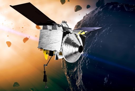 Figure 1 - OSIRIS-REx spacecraft (NASA, 2016b)
1.2 The Mission customer
In 2010 the OSIRIS-REx mission was put forward as a potential New Frontiers mission. This was a collaborative effort with the University of Arizona as the principal investigator and NASA Goddard Flight Space Centre, essentially managing the mission. The OSIRIS-REx mission along with two other mission concepts were selected for a 12 month mission concept study to assess the viability of the planned mission (Rob Gutro, 2010). In 2011 the OSIRIS-REx mission was selected as the winner (University of Arizona, 2011). The principal Investigator for the mission was Dr Michael Drake, Director of the Lunar and Planetary Laboratory at the University of Arizona. Dr Drake was involved in this initial bid phase, when the OSIRIS-REx proposal was initially being put forward. However, shortly after the program was funded, Dr Drake unfortunately died of liver cancer, in September 2011. Professor Dante Lauretta was made Dr Drake’s successor as Principal Investigator of the OSIRIS-REx mission. Due to the nature of the mission, the mission customer is essentially both NASA and the University of Arizona since they take up the role as the principal investigator. This structure of having a principal investigator is typical of New Frontiers missions.
1.3 The date of launch
The OSIRIS-REx spacecraft was scheduled to be launched on the 8th of September, 2016 from Cape Canaveral. There was a 33 day window from this date for additional attempts (NASA, 2016a). The OSIRIS-REx spacecraft was successful on the first day of the launch window, therefore being launched on the 8th of September 2016.
1.4 The operational life-time
The OSIRIS-REx spacecraft's mission duration commenced in September 2016, when the launch took place and is expected to jettison the SRC capsule on 24th of September 2023, which represents a mission lifetime of 7 years. Since the OSIRSI-REx will not be returning to Earth and will stay in orbit, the plans for the ORSIRIS-REx are not definite as the state of the spacecraft at this time will have to be evaluated for any potential missions afterwards.
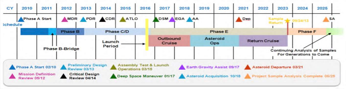 Figure 2 - OSIRIS-REx Mission timeline (OSIRIS-REx Project)
1.5 The system operator
The system operator of the OSIRIS-REx mission is predominantly NASA as they funded the majority of the spacecraft and mission. The principal investigator, Professor Dante Lauretta Direction will be providing leadership and direction to NASA for the mission and has control of most parts of the mission (Clark, 2016), Professor Dante Lauretta, is the head of the University of Arizona - Lunar and Planetary Laboratory research team. While NASA is the system operator, they have delegated this task by subcontracting Lockheed Martin to perform mission operations (NASA, 2016a).
1.6 The system users
The system users of the OSIRIS-REx mission include many different organisations and groups in the scientific community and the different user bases will have varying amounts of access to the mission data. The system users include:
1.6.1 Primary Users
The primary users of this mission include both NASA and the University of Arizona - Lunar and Planetary Laboratory research team. The project was mainly funded by NASA, which essentially gives them ultimate control over the spacecraft. However, as this is a New Frontiers mission, which requires a principal investigator, some of this control is effectively delegated to the principal investigator, which in this case is Professor Dante Lauretta and his team from the University of Arizona. Professor Lauretta's team, the Lunar and Planetary Laboratory at the University of Arizona will essentially be the primary benefactors of the mission data along with NASA.
1.6.2 Future Users
The OSIRIS-REx mission is rather complex and costly. If the mission is a success, mankind will have access to very unique asteroid samples, which have never been obtained before. Due to the immense amount of effort which was required to obtain these samples, steps have been put in place so that the sample which is collected is preserved for the future. This will enable future generations of scientists, with more advanced technologies to study the sample and potentially find new information about the sample, which present day technology cannot. For this reason NASA have guaranteed that at least 75% of the sample will be preserved for future generations of scientists.
1.6.3 Mapping data generated by OSIRIS-REx
The OSIRIS-REx mission will generate a wide array of various data. An example is the mapping data of Bennu. This will consist of high resolutions maps of Bennu. This is generated from the suite of sensors mentioned below and are used as described below, to generate the map data. This data, while critical for the mission, represents a product in itself, which can be studied for future generations to come. An explanation of this is detailed below:
- Bennu Map Data – The OSIRIS –REx spacecraft will complete quite an in-depth mapping campaign as it orbits around Bennu. It will include both global mapping of the entire asteroid and localised mapping in certain locations to provide a high enough resolution in which a penny could be detected on its surface. The mapping data will also include the mineral composition of Bennu. This data will be used to determine the optimal sampling site for the OSIRIS-REx to take samples. The mapping campaign will utilise the complex sensor suite aboard the OSIRIS – REx spacecraft. These sensors include:
- OCAMS – OCAMS is a camera suite which will be used for the global mapping of Bennu. OCAMS is made up of three cameras, PolyCam, MapCam and SamCam. PolyCam and MapCam will be used for specifically for the mapping. These cameras are detailed further in the Spacecraft Payload section.
- Laser Altimeter (OLA) – This will allow the spacecraft to determine the distance between it and Bennu thus allowing the exact shape of the asteroid to be mapped. This works in a very similar way to how a laser scanner is used in 3D printing works.
- Visible and Infrared Spectrometer (OVIRS) – This will allow the OSIRIIS-REx to measure both the visible and infrared light from Bennu and can be used to assist in determining the surface composition of the asteroid.
1.7 The launch vehicle and launch procedure
The Launch vehicle used for the OSIRIS-Rex mission was an Atlas V 411 rocket. The Atlas 5 launch system is operated by a joint venture between Boeing and Lockheed Martin called United Launch Alliance (ULA).
The Atlas V rocket is a dual stage expendable rocket. The first stage, is referred to as the Common Core Booster (CCB). This burns 284,450 kg of liquid oxygen as well as RP-1 and is a Russian RD-180 main engine. This is supplemented with a single additional strap-on solid rocket booster.
The subsequent stage is a Centaur second stage engine propelled by a cryogenic propellant with an Aerojet Rocketdyne RL10A-4-2.
As previously mentioned, the launch took place from Cape Canaveral Air Force Station with the launch date being set for the 8th of September 2016 with a 33 day launch window. Luckily, the OSIRIS-REx was able to be launched on the first day of this period.
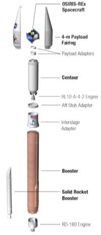 Figure 3 - Launch Configuration of the Atlas V rocket carrying the OSIRIS-REx spacecraft (NASA, 2016a)
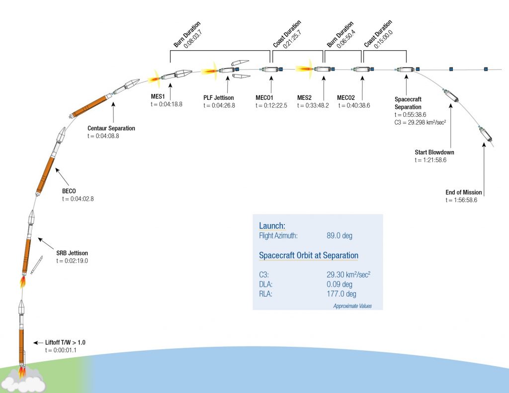 Figure 4 - Launch profile of the Atlas V rocket with the OSIRIS-REx on board (NASA/United Launch Alliance, 2016)
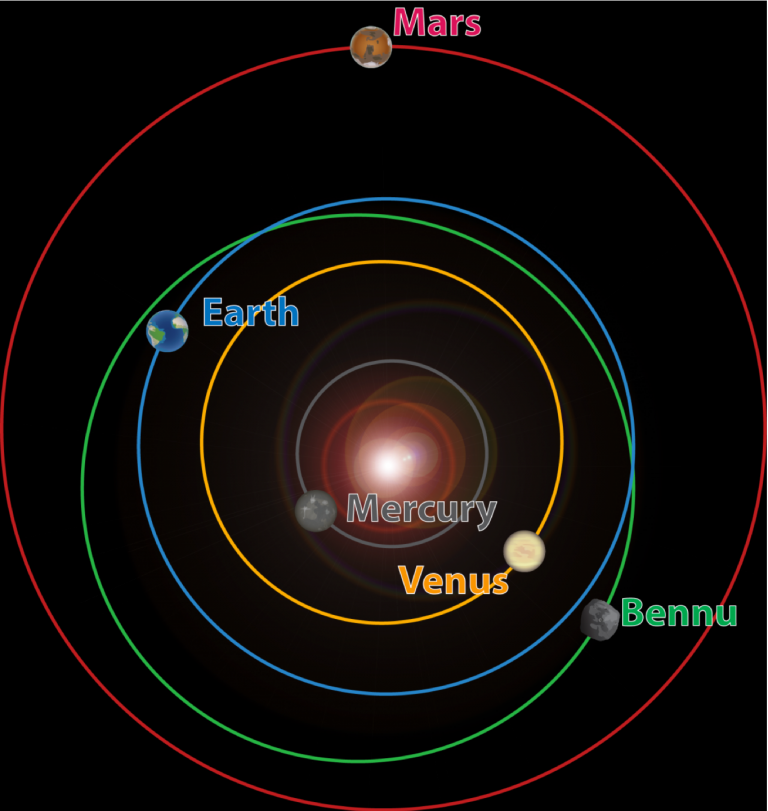
1.8 The trajectory followed by the spacecraft on its flight to and from its target
The OSIRIS-Rex was launched from Cape Canaveral, with a hyperbolic escape velocity of 5.4km/s. Once the OSIRIS-REx leaves Earth’s atmosphere it will perform a series of Deep Space Manoeuvres, which will change the velocity by 0.52km/s. The OSIRIS-REx spacecraft will then spend a year orbiting the Sun.
After this year of orbiting the Sun, the OSIRIS-Rex will perform what is known as a ‘slingshot manoeuvre’. It will fly relatively close to Earth and thereby enter back into Earth’s gravitational field, which will pull it towards Earth. This allows the OSIRIS-REx to borrow a small amount of Earth’s orbital energy. This will result in both a changed orbital inclination and a push back into space, towards a rendezvous with Bennu for the OSIRIS-REx craft.
When approaching Bennu in August 2018, the OSIRIS-REx will use an array of small on board rocket thrusters to match the velocity of the asteroid. When the ORISIRS-REx is approaching Bennu it will have a relative approach velocity of 20cm/s.
When the OSIRIS-REx has arrived to less than 10km of Bennu it will start to basically orbit Bennu, thus allowing the on-board sensors to map every part of the asteroid.
Once all tasks have been completed and a sample of the asteroid is safely stowed away, OSIRIS-REx will commence the return trip back towards Earth. The first opportunity for departure of Bennu is March 2021. When this time arrives the OSIRIS-REx will fire its main engines and will depart Bennu. This will place the spacecraft on a trajectory, which intersects the orbit of Earth in September 2023.
When the spacecraft is four hours away from reaching the atmosphere of Earth, the OSIRIS-REx will jettison the Sample Return Capsule (SRC) towards Earth. OSIRIS-REx will then perform a deflection manoeuvre which will place the spacecraft in a stable orbit around the Sun. Once the OSIRIS-Rex returns the SRC, the craft would have travelled 7 billion kilometres (Lockheed Martin Space Systems, 2017). As mentioned in 1.4, depending on the state of the spacecraft will depend on what the spacecraft is tasked to do next.
The jettisoned SRC will be traveling towards the Utah desert at a speed of 12.4km/s as it travels through the top of Earth’s atmosphere. After entry the SRC will free fall towards Earth until it reaches an altitude of 33.5km, which will trigger the deployment of the drogue parachute. As the SRC is travelling towards the Utah desert, the main parachute is released, which will enable the capsule to have a soft landing in a US military test range in Utah. The estimated date will be September 2023 (NASA, 2016a).
 Figure 5 - The orbit of Bennu relative to the Earth and Sun (Lauretta)
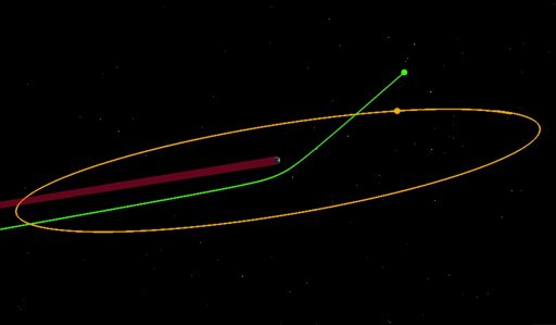 Figure 6 - The trajectory created by the Earth Gravity Assist manoeuvre (University of Arizona)
1.9 The spacecraft payload
The payload which will be carried by the OSIRIS-Rex consists mainly of imaging instruments, along with collection equipment to collect samples of the Bennu asteroid. In total, there are eight instruments carried on OSIRIS-REX, six being imaging and two being related to the collection and return of a sample of the asteroid. The eight instruments on the OSIRIS-REx include a Camera Suite (OCAMS), Laser Altimeter (OLA), Thermal Emission Spectrometer (OTES), Visible and Infrared Spectrometer (OVIRS), X-Ray Imaging Spectrometer (REXIS), Touch and Go Sample Acquisition Mechanism (TAGSAM), Touch and Go Camera System (TAGCAMS), Sample Return Capsule (SRC) (NASA, 2016a). These seven instruments are explored in detail below: The imaging instruments consist of six instruments, which will allow scientists to map with a high resolution and determine the composition of the asteroid so that there is information known about the distribution of elements, minerals and organic material. This will then allow the optimal sampling site to be determined so that a successful sample can be taken. The imaging instruments consist of:
- OSIRIS-Rex Camera Suite (OCAMS) – This system will observe Bennu and provide global image mapping as well as detailed mapping of recommended sites to obtain a sample of the asteroid. The OCAMS consists of three cameras and were provided by the University of Arizona and consist of:
- MapCam –The MapCam is a high resolution camera which will be used to map the surface of Bennu in four colours from a distance of approximately three miles.
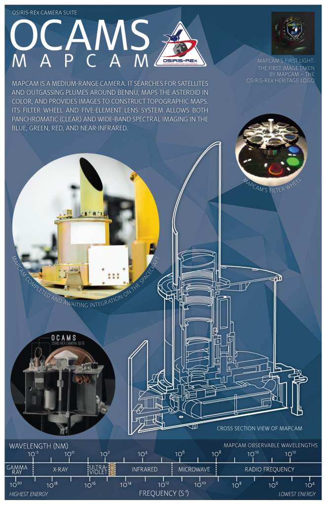
Figure 7 - MapCam Overview (NASA, 2015a)
- PolyCam – Polycam is the largest of the three cameras on the OSIRIS-REx, it is a dual-purpose camera, which has very high zoom. It is highly versatile as it can both function as a telescope, thereby acquiring the image of an asteroid which is very far away and can also function as a microscope, which can be used to analyse rocks and pebbles on the surface of the asteroid.
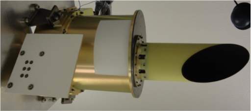
Figure 8 – PolyCam (Lauretta, 2014a)
- SamCam – The SamCam will be used during the sampling phase of the mission. The SamCam will be used to check the collected asteroid rocks, thereby ensuring that there has been a successful collection.]
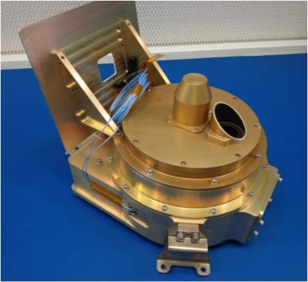
Figure 9 – SamCam (Lauretta, 2014b)
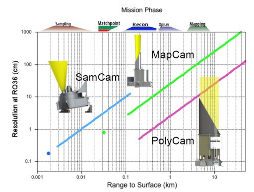 Figure 10 - OCAMS Coverage (University of Arizona, 2013)
- Touch and Go Camera System (TAGCAMS) – The Touch and Go Camera System is used to support the spacecraft for navigation and engineering purposes (Lakdawalla, 2016). The system consists of two camera systems, that being:
- NavCams – Navigational cameras which form part of the navigation, guidance and control system on the OSIRIS-REx. By analysing the sky and certain stars, they are used for optical navigation of the spacecraft. There are two Malin Space Science CAM-M50 5 megapixel cameras, which makeup the NAVCAMS system.
- StowCam – This high definition Malin Space Science CAM-C50 5 megapixel colour camera will image the transfer of the asteroid sample from the TAGSAM to the Sample Return Capsule (SRC).
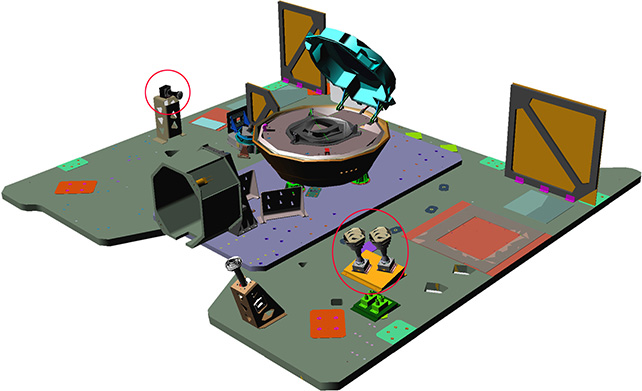
Figure 11 - TAGCAMS System (Malin Space Science Systems, 2014)
- OSIRIS-REx Laser Altimeter (OLA) – The OLA is an active device in that it is a scanning LIDAR (Light Detection and Ranging) instrument which will be used to collect data from the surface of Bennu, thus in turn will produce three dimensional topographic maps of the asteroid. It can do so from a distance of up to 7.5km away. A LIDAR essentially functions very similarly to a radar, in that it sends out a pulse of light and waits for it to return. The time taken for this pulse to be received is halved and then can be converted to a distance. The OLA utilises two lasers, the first one is a high powered laser in that it can operate between 1-7.5km while the second is lower powered and can be used at distances of less than 1.5km. The OLA was contributed from the Canadian Space Agency especially for the OSIRIS-REx mission.
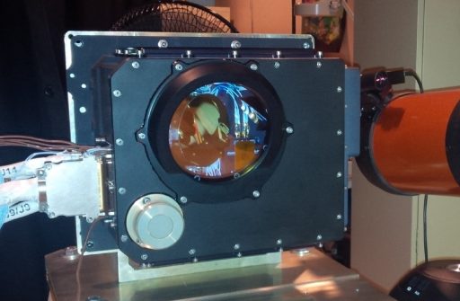
Figure 12 – OLA (MacDonald Dettwiler and Associates Ltd (MDA), 2015)
- OSIRIS-REx Thermal Emission Spectrometer (OTES) – The OTES is a passive device, in that it is a spectrometer, which will collect thermal infrared data with wavelengths between 5 and 50µm. The OTES’s primary purpose is to develop thermal emission and spectral global maps as well as local potential sample sites. Secondly the OTES will also measure the surface temperature and the total thermal emissions originating from Bennu. The OTES was contributed from Arizona State University (ASU) especially for the OSIRIS-REx mission.
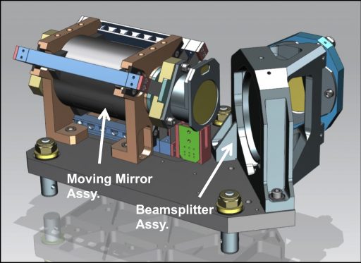
Figure 13 – OTES (Lauretta, 2015b)
- Visible and Infrared Spectrometer (OVIRS) – The OVIRS is a passive device, in that it is a spectrometer, however, unlike the OTES, this will measure much narrower wavelengths of light reflecting off the surface of Bennu, between 0.4-4.3µm. Like OTES this data will be used to produces spectral maps of the asteroid to help determine potential sample sites for the mission.
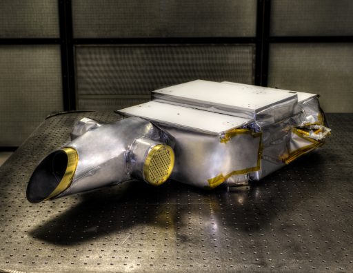
Figure 14 - OVIRS Instrument (NASA, 2015b)
- X-Ray Imaging Spectrometer (REXIS) – The last imaging instrument carried on the OSIRIS-REx spacecraft is the REXIS. This is also a passive device, as it is a spectrometer which is designed to collect and image fluorescent X-rays, which have been emitted by the Asteroid. This is designed to collect data about the regolith of Bennu. The REXIS is a student science experiment, from both students of Harvard University (HU) and Massachusetts Institute of Technology (MIT).
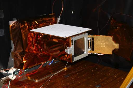
Figure 15 - REXIS Instrument (Lauretta)
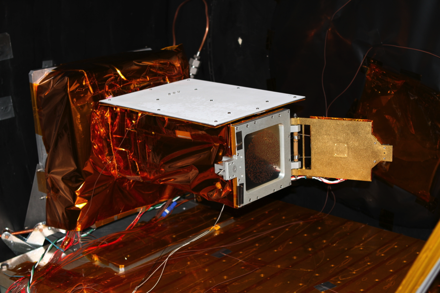
- Touch and Go Sample Acquisition Mechanism (TAGSAM) – The TAGSAM will collect regolith samples from Bennu. It comprises of a sampling head with surface contact pads, which resembles a net with Velcro, which contains a nozzle of nitrogen. When sampling, the sampler head makes contact with the surface of Bennu and the jet of nitrogen is applied to disturb the surface. Once sampled, the robotic arm will move the sampler head to within view of SamCam to verify that a sufficient sample has been captured. The sample will be weighed. If the sample is successful the robotic arm will place the sampler head into the SRC for secure storage. If a sufficient sample has not been collected, the process of collecting a sample will repeat with enough nitrogen for two more attempts.
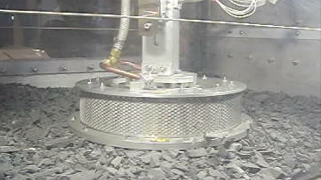
Figure 16-Testing the sampling head (Lockheed Martin Space Systems)
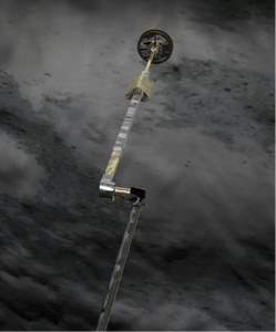 Figure 17- The testing of the TAGSAM (Lockheed Martin Space Systems)
- OSIRIS-REx Sample return capsule (SRC) – The Sample Return Capsule is one of the most important payloads on the spacecraft. Its job is to return the sample of the asteroid in a pristine condition. The successful return of surface samples of the asteroid is the major objective of the OSIRIS-REx mission. For this reason, after the sample has been taken, the OSIRIS-REx mission risk profile will become very conservative, with no additional experiments to take place and the OSIRIS-REx craft will be sent directly back towards Earth (NASA, 2016c).

Figure 18 - Instrument Deck of the OSIRIS-REx(NASA, 2016a)
1.10 The space segment architecture
The OSIRIS-REx spacecraft consists, of two main sections – the spacecraft bus and the payload (instruments which will be used to fulfil the mission) in this case collect data from Bennu. The spacecraft bus is responsible for facilitating the mission objectives, which is the collection of data from Bennu. To enable the spacecraft to facilitate these objectives it has a complex network of systems which include Propulsion, Attitude Control, Navigation, Thermal Management, Power, Data Processing and Communications.
1.10.1 Propulsion System
For the spacecraft to control its trajectory it requires a method of changing direction and velocity. The OSIRIS-REx spacecraft utilises 28 different Hydrazine Monopropellant thrusters. The different categories of thrusters on the spacecraft are:
- 4 x High Thrust, Aerojet Rocketdyne (AR) MR-107S, for large delta v manoeuvres including the Earth Flyby, Asteroid Approach Braking Burn and the Asteroid Departure Burn. These thrusters have a Nominal thrust of 275N
- 6 x 22N Medium Thrust AR MR-106L thrusters used for pitch and yaw control during High thrust manoeuvres.
- 16 x low thrust 4.5N AR AMR-111G thrusters provide attitude control thrust.
- 2 x ultralow thrust AR MR-401 AR thrusters– Used for the Touch and Go manoeuvre.
All 28 thrusters are fed from a central Hydrazine tank in the spacecraft with a volume of 1300litres and the capacity to hold up to 1245kg of propellant. The Propulsion system on the OSIRIS-REx spacecraft is based on the type of system which was used on various Mars missions including the orbiter and MAVEN.
1.10.2 Power System
The power system on the OSIRIS-REx utilises a complex system of power components. Power is generated from 2 x Gallium Arsenide solar panels. These high performance solar panels have a span of 6.2m with an active area of 8.5m^2 and an approximate efficiency of around 38%. The solar panel cannot actively track the Sun but requires the spacecraft to move. The solar panels do however, have a gimbaling function which will allow them to rotate away from the surface of Bennu, during the sampling event to ensure that they do not get coated in dust. Power is stored in 2 x 30Ah EaglePicher lithium-ion batteries (EaglePicher Technologies, 2016) with integrated Battery Management Systems (BMS). The power supply system on the spacecraft handles the distribution and regulation on the spacecraft.
1.10.3 Attitude determination and Control
For a spacecraft to control its attitude it requires a control system to detect and then control its attitude. The OSIRIS-REx utilises an advanced system of sensors and actuators to keep its attitude aligned. The sensor system consists of a primary and secondary system. The primary system utilises two star trackers, which acquire optical images of the star filled sky and utilise on-board algorithms, which rely on data from a database of known stars and from that a 3 axis orientation of the spacecraft can be determined. The secondary system consists of two Inertial Measurement Units (IMU), which can also derive the attitude of the spacecraft. Additionally, Sun sensors are also installed on OSIRIS-REx in case the systems safe mode is activated. This way if an event occurred on the spacecraft, which trigged the safe mode, such as a system fault etc., the Sun sensors would be used to enable the spacecraft's solar panels to point towards the Sun to ensure the spacecraft would have sufficient power. Attitude Control on the OSIRIS-REx is provided by various actuators on the spacecraft. These include the medium and low thrust thrusters and reaction wheels installed on the spacecraft. Different actuators are used depending on the objective of the attitude adjustment.
1.10.4 Navigation
Navigation is provided on-board the OSIRIS-REx from the data derived from the two different sensors. The first sensor is TAGCAMs, which is a three camera, wide field of view system which forms part of the payload of the spacecraft. This can be used for optical navigation predominantly when the spacecraft is within view of Bennu.
The second sensor is a 3 dimensional LIDAR. The LIDAR (Light Direction and Ranging) is used to measure the distance between itself and a target. The transmitting component is a Laser which sends pulses of light. When the light returns it will be measured and therefore distance can be obtained. Additionally, since this LIDAR is a 3D type, there are 16384 separate receivers essentially. These are arranged on a 128x128 matrix which is similar to an image sensor on a camera. By detecting the time difference of the light which has been received on each of the sensors, 3D data of the target surface can be determined.
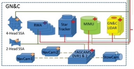 Figure 19 - OSIRIS-REX's Attitude Control and Navigational System (NASA/Lockheed Martin, 2015a)
1.10.5 Data and Processing
The processing choice on OSIRIS-REx has never been released to the public (SPACEFLIGHT101, 2016). Based on the hardware reuse which the OSIRIS-REx mission utilises from other Mars missions, we can assume it was most likely the RAD750. The BAE Systems RAD750 is a single board computer (SBC). The CPU can tolerate very high radiation doses, up to 1 million times the fatal radiation dose for a human. The SBC is also very reliable, on average over 15 years the device is specified to only encounter 1 interrupt (system failure). The RAD750 only consumes 10W of power and can operate over a temperature range of –55->155°C.
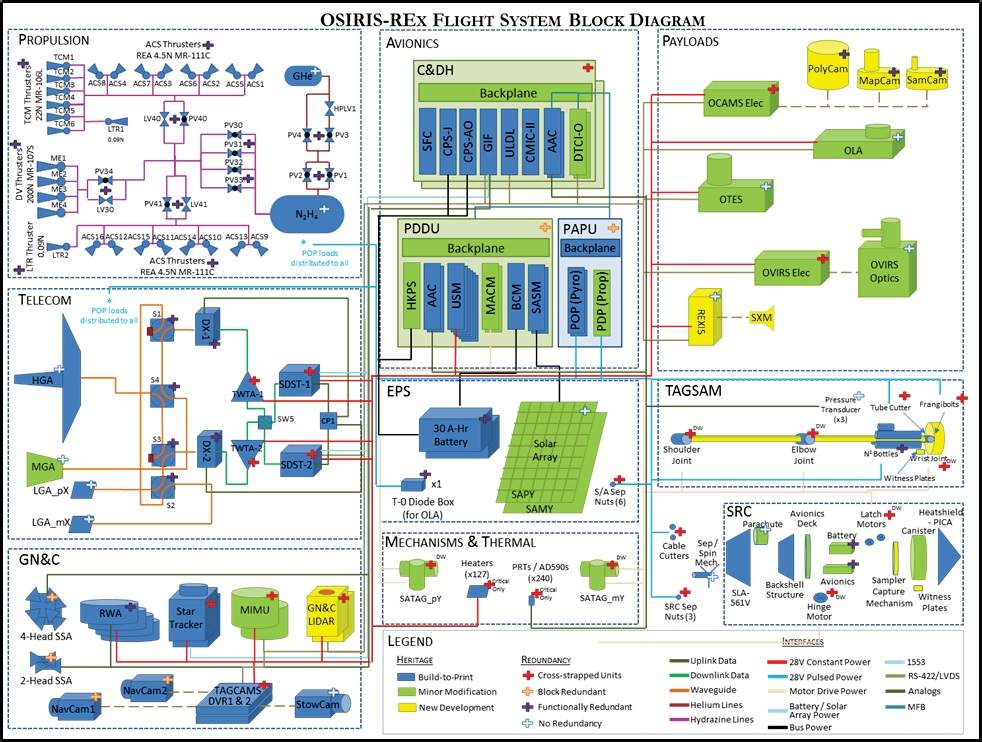 Figure 20 - OSIRIS-REx's Functional Block Diagram (NASA/Lockheed Martin, 2015b)
1.11 The ground segment architecture
Due to the enormous distance which the OSIRIS-REx spacecraft is from Earth, it will communicate to Earth via NASA’s Deep Space Network (DSN). The DSN utilises 3 ground stations located at unique sites around the world, which typically provides 24/7 tracking while the Earth rotates. The three sites are located in:
- Madrid, Spain has 7 antennas, with its largest being a 70m parabolic reflector.
- Goldstone, USA has 5 antennas, with its largest being a 70m parabolic reflector.
- Canberra, Australia has 4 antennas, with its largest being a 70m parabolic reflector.
Due to the distance that OSIRIS-REx is away from Earth and the power being transmitted, only a 34m parabolic ground station antenna is typically needed for the tracking of the spacecraft. If we compare this to a spacecraft like Voyager 2, generally a 70m antenna is needed for its increased gain, in order to receive a good quality Voyager 2 signal.
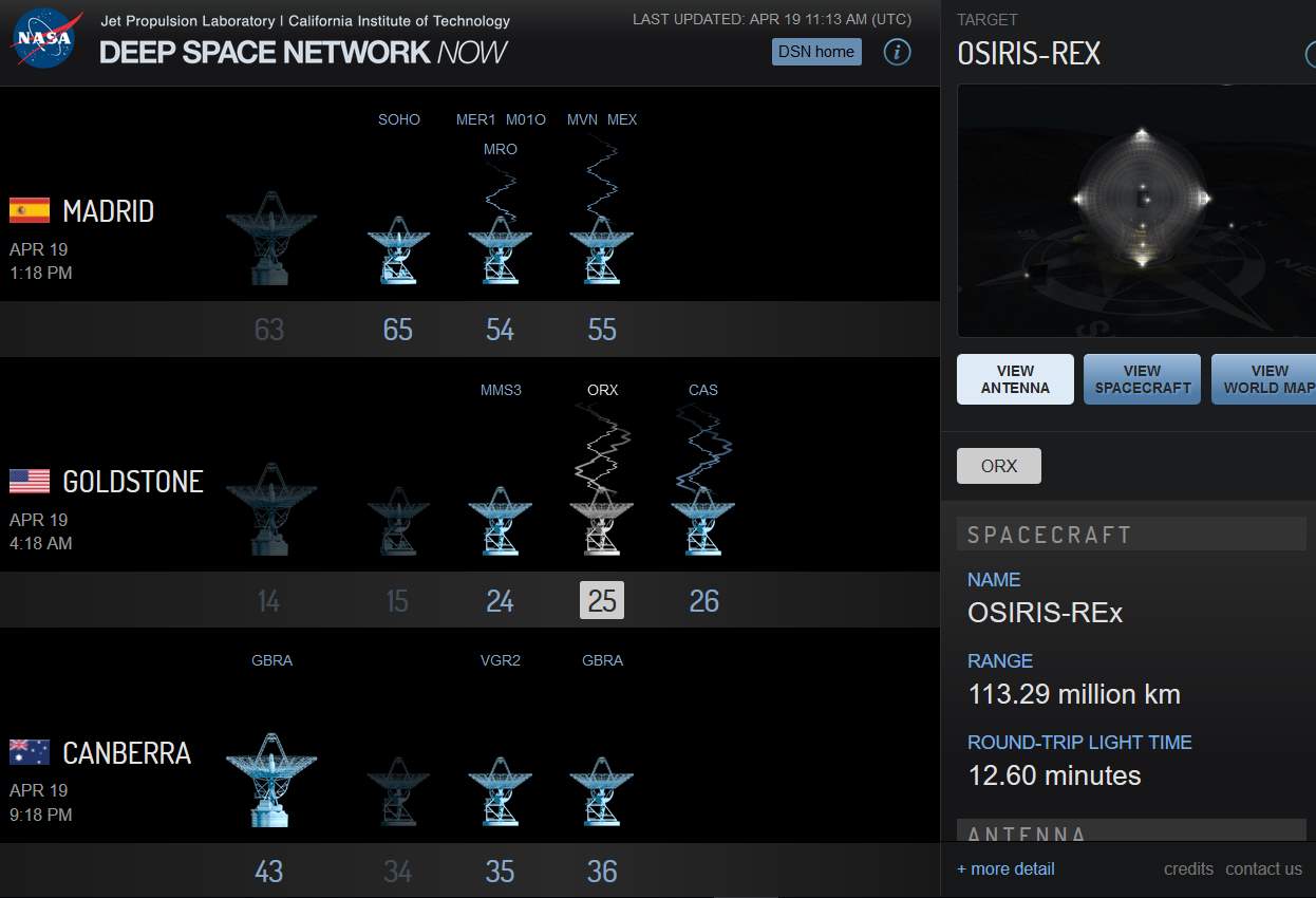 Figure 21 - Screenshot showing that the OSIRIS-REx is being tracked by a 34m parabolic antenna in Goldstone, USA (NASA, 2017)
1.12 The major mission developers
The OSIRIS-Rex mission was quite a complex mission and it had many different stakeholders involved in the design of the spacecraft and the various instruments, which make up the payload. NASA’s Goddard Space Flight Centre provided the overall mission planning, safety assurances, project management and requirements to each of the relevant subcontractors involved in producing the different parts for the mission.
1.12.1 Lockeheed Martin Space Systems
Lockheed Martin Space Systems built the OSIRIS-REX spacecraft bus and performed the system integration. They are also responsible for the mission operations.
1.12.2 Malin Space Science Systems
The OSIRIS-REx mission utilises three Malin Space Science Systems cameras which form the TAGCAMS system. The two major components of the TAGCAMS system are NavCams and StowCam.
As previously mentioned, the NavCams consist of two CAM-M50 5-megapixel monochromatic cameras. Two are used to bring a level of redundancy to the navigational system on-board the OSIRIS-REx. The third Malin Space Sciences camera is an ECAM-M50 5-megapixel colour camera which is referred to as StowCam. All three cameras are capable of acquiring still images and high definition video.
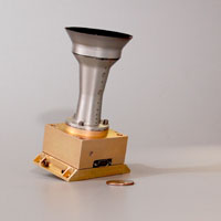 Figure 22 - ECAM-C50 (MSSS, 2017)
1.12.3 Canadian Space Agency (CSA)
The Canadian Space Agency contributed the OSIRIS-REx Laser Altimeter (OLA) to the mission. This was a project which was run in collaboration with a Canadian-US led team, led by Michael Daly who was the OLA instrument scientist at York University, while Catherine Johnson was the deputy OLA instrument scientist at the University of British Columbia. Oliver Barnouin also assisted and was from Johns Hopkins University (NASA, 2016a).
1.12.4 Arizona State University (ASU)
ASU contributed to the OSIRIS-REx mission by building the OSIRIS-REx Thermal Emission Spectrometer (OTES). This team was led by Phillip Christensen, instrument scientist at ASU with assistance from Victoria Hamilton, who was the deputy instrument scientist at Southwest Research Institute (SwRI).
1.12.5 Harvard University (HU) and Massachusetts Institute of Technology (MIT)
HU and MIT ran a collaborative student project to design and build the Regolith X-Ray Imaging System (REXIS) for the OSIRIS-REx mission.
1.12.6 University of Colorado (CU)
The Radio Sciences team helped develop the telecommunications subsystem aboard OSIRIS-REx and will use high and low gain antennas to communicate with the Deep Space Network (DSN). They will use the Doppler shift from the carrier wave to make a range of measurements about the mass and gravity field that is being faced by the OSIRIS-REx. The radio science team is led by Daniel Scheeres from CU.
1.12.7 NASA Goddard Space Flight Centre
As described above, apart from the overall mission planning, safety assurances, project management, The Goddard Space Flight centre developed the OSIRIS-REx Visible and Infrared Spectrometer (OVIRS) system specifically for the OSIRIS-REx mission.
1.13 The communication system
The OSIRIS-Rex space craft’s Telecommunications Subsystem will use any one of three antennas that being a low gain (LGA), medium gain (MGA) and high gain antenna (HGA) to communicate back to Earth. The telecoms system is essentially a clone of the system on board NASA’s Mars Atmosphere and Volatile Evolution mission (MAVEN). The core of the OSIRIS-REX’s telecommunication system is a Small Deep Space Transponder (SDST) and a Travelling Wave Tube Amplifier (TWTA). There are two sets of these devices installed on the OSIRIS-REx spacecraft in the interests of redundancy. The SDST is a NASA/JPL design and is typically used for deep space missions as it integrates numerous functions into a single unit including receiver, telemetry, command detection, modulation, exciters, control and tone generation. The unit supports frequencies in both the X and Ka band and has a mass of 4kg. Depending on the distance away from Earth, data rate needed and ability to accurately point the spacecraft dictates whether a low, medium or high gain antenna is used on the spacecraft. The three antennas offer different features including:
- Low Gain Antenna (LGA) – The LGA utilises two chocked horn antennas. The result of these antennas give the spacecraft Omni-directional coverage, therefore allowing the spacecraft to be pointed in any direction. However, the data rate is very low as the system uses MFSK tones.
- Medium Gain Antenna (MGA) – The MGA is a circular horn antenna, which allows an increased data rate, however it has a limited beamwidth. This works well when the spacecraft is roughly pointing in the right direction and essentially offers a middle ground between the other two antennas. For this reason, the MGA will be used in the critical Touch and Go sampling operation when the OSIRIS-REx takes a sample of the asteroid.
- High Gain Antenna (HGA) – The HGA is a highly directional antenna. It is a 2.1m diameter parabolic antenna. Since we know the frequencies used are both X-band and Ka Band, this results in a 3dB beamwidth from the antenna of between 0.2°-1.2°. This allows the spacecraft to send data back to Earth at a much higher data rate of up to 914kbits/s, while the spacecraft is accurately pointing towards Earth.
As mentioned above, communication to Earth will be via NASA’s Deep Space Network (DSN). This network can obtain accurate Doppler and range measurements of the spacecraft, which can be used to measure the mass and gravity field of Bennu. The communications side of the mission is led by Daniel Scheeres at the University of Colorado.
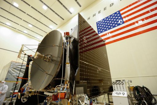 Figure 23 - OSIRIS-REx's HGA parabolic antenna (NASA/Lockheed Martin)
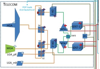 Figure 24 - OSIRIS-REx Telecommunications subsystem schematic (NASA/Lockheed Martin)
2. Budget Calculations
2.1 Mass Budget
2.1.1 Research
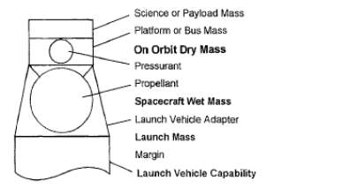
Two of the key masses of the OSIRIS-REx spacecraft are published, that being the Dry and Wet mass. For the system’s mass budget to be determined, there are still two masses which need to be obtained as from extensive research, a payload mass and a Launch Vehicle Capability is unable to be obtained. There are generic Launch vehicle capabilities for the Atlas V rocket, however the OSIRIS-REx utilises a custom configuration of the Atlas 5. Therefore, going forward, some reasonable estimates shall be made for the remaining masses.
Since the On Orbit dry mass is given of 880kg, this mass can be used to estimate a payload mass. Figure 2.7 of Elements of Spacecraft Design (Brown, 2002), illustrates that for a planetary spacecraft with an on orbit dry mass of 880kg, a typical payload mass would be approximately 116kg.
From these three masses, all that is left is a Launch Vehicle Capability mass or a Launch Vehicle Adaptor mass and then we can deduce the entire set of spacecraft specific masses. This mission is quite unique in that in the initial design stage there was a small mass margin of 33kg (Lauretta, 2015a). However, it was determined that the wet mass will actually be greater than the launch vehicle capability of 1955kg. The launch mass with the propellant tanks full will be 2110kg. As a result of this, the launch provider United Launch Alliance (ULA) performed a study to determine the absolute limit which can be launched.
The study concluded that the Atlas V can support a launch mass of 2078kg, and hence the propellant tanks were therefore filled until the entire spacecraft had a wet mass equal to the launch capability and thus there was a margin of 0kg (Lauretta, 2015a). However, a NASA press release after this study states the wet mass at launch was 2110kg (NASA, 2016a). This tell us that the propellant tanks were at 100% capacity upon launch.
It is important to note when conducting research and hence the findings above, when talking about Launch Vehicle Capability, I believe that the sources are ignoring the Launch Vehicle Adaptor mass in the Launch Vehicle Capability calculations therefore, I assume its mass has already been accounted for and included in the Launch Vehicle mass. I believe this to be the case as Professor Dante Lauretta, Principal Investigator of OSIRIS-REx mission states that “We will simply add the extra fuel until the wet mass equals the launch vehicle capability”(Lauretta, 2015a).
The Launch vehicle adaptor mass can be estimated based on historical missions by the following equation, as given in Elements for Spacecraft design (Brown, 2002):
LVA=0.0755*LM+50
Since the Launch Mass in this standard formula includes the LVA (unlike the OSIRIS-REx Launch mass/wet mass) we can say that LM=LM_rex+LVA, LM_rex=2110kg.
LVA=0.0755*LMrex+LVA+50
This results in a LVA mass =226kg.
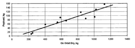 Figure 25 - Payload Mass vs On Orbit Dry Mass (Brown, 2002)
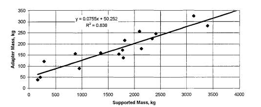 Figure 26 - Launch Vehicle Adaptor Mass (Brown, 2002)
2.1.2 Calculations and Results
Dry Mass=Md=880kg (NASA, 2016a){Arizona`;, 2015 #5}{NASA, #6}
Wet Mass=Mw=2110kg (NASA, 2016a)
Payload Mass=Mp=116kg
Mass of Propellant + Pressurant = Mpp=Mw-Md=1230kg
Bus Mass=Mb=Md-Mp=764kg
Launch Vehicle Adaptor = LVA= 226kg
Launch Vehicle capability=2326kg
2.2 The Spacecraft Power budget
2.2.1 Research
The OSIRIS-REx spacecraft's primary source of power is from two solar arrays which generate between 1226W to 3000W depending on the spacecraft's distance from the Sun. Electricity will be stored in two 8 cell 28V 30Ah (1680Wh) Li-ion batteries with integrated battery management systems (BMS) as previously discussed. Since this data tells us that when the spacecraft is further from the Sun, the minimum power being produced will be 1226W, we can say that the spacecraft will typically be able to operate on this minimum level of power. This is based on the trajectory of the mission, in that it will be away from the Sun for some time, and since the OSIRIS-REx has only 1680wh of battery storage, the spacecraft will effectively need to be able to sustain its operations from the minimum power of 1226W. However this is not to say that the system won’t survive on less power, it most likely would, it only says that the spacecraft can most likely function, (at least at a minimum level) for extended periods on 1226W of power. Attempts have been made to quantify the power requirements of the payload, however, there was not much success on this front, due to a lack of published specifications, therefore exact payload and subsystem power requirements could not be made. As a result we can use estimates based on previous planetary missions. The textbook “Elements of Spacecraft Design” (Brown, 2002), Table 2.9, page 33, demonstrates that for a typical planetary mission, the payload power requirement can be expressed as: Pt=332.93*lnPpl-1046.6 Pt=Total Power P_pl=Payload Power
2.2.2 Calculations and Results
Payload Power -> 1226=332.93*ln(Pl)-1046.6, P_Pl=921W Therefore we can estimate a subsystem power of =1226-921=305W Since we are making estimations it would be prudent to use a conservative margin value. For this reason, a margin value of 0.7 will be used for calculations This results in a margin of 0.7*305=213.5W In the Textbook “Elements of Spacecraft Design” (Brown, 2002) Table 2.10, outlines the figures of a typical power distribution for a Planetary mission, from these figures we can estimate the power used by each of the subsystem components as:
| Subsystem | Power distribution for planetary spacecraft (Brown, 2002) % | Power Allocation for OSIRIS-REx based on 100%=305W W |
| Thermal control | 28 | 85.4 |
| Attitude control | 20 | 61 |
| Power | 10 | 30.5 |
| CDS | 17 | 51.8 |
| Communications | 23 | 70.15 |
| Propulsion | 1 | 3.05 |
| Mechanisms | 1 | 3.05 |
Figure 28 - Power Estimation of various subsystem components on OSIRIS-REx
References
BROWN, C. D. 2002. Elements of Spacecraft Design. CLARK, S. 2016. OSIRIS-REx reaches launch pad with money to spare [Online]. Spaceflight Now. Available: https://spaceflightnow.com/2016/09/07/osiris-rex-reaches-launch-pad-with-money-to-spare/ [Accessed 08/04/2017 2017]. EAGLEPICHER TECHNOLOGIES. 2016. OSIRIS-REx Spacecraft Launched Carrying EaglePicher Batteries [Online]. Available: http://www.eaglepicher.com/m/news/eaglepicher-news/436-osiris-rex-spacecraft-launched-carrying-eaglepicher-batteries [Accessed]. LAKDAWALLA, E. 2016. OSIRIS-REx’s cameras see first light [Online]. Available: http://www.planetary.org/blogs/emily-lakdawalla/2016/09290125-osiris-rex-cameras-first-light.html [Accessed]. LAURETTA, D. Orbit of Asteroid Bennu [Online]. Available: http://spaceflight101.com/osiris-rex/wp-content/uploads/sites/103/2016/08/orbit-768x811.png [Accessed 04/05/2017]. LAURETTA, D. REXIS Instrument [Online]. Available: http://spaceflight101.com/osiris-rex/wp-content/uploads/sites/103/2016/08/rexis-em.png [Accessed 01/05/2017]. LAURETTA, D. 2014a. PolyCam [Online]. Available: http://spaceflight101.com/osiris-rex/osiris-rex-instruments/ [Accessed 02/04/2017]. LAURETTA, D. 2014b. SamCam [Online]. Available: http://spaceflight101.com/osiris-rex/osiris-rex-instruments/ [Accessed 02/04/2017]. LAURETTA, D. 2015a. The OSIRIS-REx Heavy Launch Opportunity [Online]. Available: https://dslauretta.com/2015/02/08/the-osiris-rex-heavy-launch-opportunity/ [Accessed 28/04/2017 2017]. LAURETTA, D. 2015b. OTES [Online]. Available: 01/05/2017 [Accessed 01/05/2017]. LOCKHEED MARTIN SPACE SYSTEMS TAGSAM testing. LOCKHEED MARTIN SPACE SYSTEMS. 2017. OSIRIS-REx [Online]. Available: http://lockheedmartin.com/us/products/osirisrex.html [Accessed]. MACDONALD DETTWILER AND ASSOCIATES LTD (MDA). 2015. OLA [Online]. Available: http://spaceflight101.com/osiris-rex/osiris-rex-instruments/ [Accessed 01/05/2017]. MALIN SPACE SCIENCE SYSTEMS. 2014. OSIRIS-REx Touch-and-Go Camera System (TAGCAMS) [Online]. Available: http://www.msss.com/all_projects/osiris-rex-tagcams.php [Accessed 01/05/2017]. MSSS 2017. ECAM-C50. NASA. 2015a. OSIRIS-REx Mission [Online]. Available: http://www.asteroidmission.org/objectives/instruments/ [Accessed 02/05/2017]. NASA. 2015b. OVIRS [Online]. Available: http://spaceflight101.com/osiris-rex/osiris-rex-instruments/ [Accessed 01/05/2017]. NASA 2016a. OSIRIS-REx Press Kit. NASA. 2016b. OSIRIS-REx Spacecraft [Online]. Available: http://spaceflight101.com/osiris-rex/osiris-rex-spacecraft-overview/ [Accessed 04/05/2017]. NASA. 2016c. The Science of OSIRIS-REx [Online]. Available: https://www.youtube.com/watch?v=Fu2Z5ZC1HBo&t=1307s [Accessed]. NASA. 2017. Deep Space Network Now [Online]. Available: http://eyes.nasa.gov/dsn/dsn.html [Accessed 19/04/2017]. NASA/LOCKHEED MARTIN OSIRIS-REx Telecommunications subsystem schematic. NASA/LOCKHEED MARTIN. 2015a. OSIRIS-REX's Attitude Control and Navigational System [Online]. Available: http://spaceflight101.com/osiris-rex/osiris-rex-spacecraft-overview/ [Accessed]. NASA/LOCKHEED MARTIN. 2015b. Spacecraft Functional Block Diagram [Online]. Available: http://spaceflight101.com/osiris-rex/osiris-rex-spacecraft-overview/ [Accessed 02/05/2017]. NASA/UNITED LAUNCH ALLIANCE. 2016. OSIRIS-REx Launch Profile [Online]. Available: http://spaceflight101.com/osiris-rex/osiris-rex-mission-profile/ [Accessed 04/05/2017]. OSIRIS-REX PROJECT. Mission Timeline [Online]. NASA. Available: http://spaceflight101.com/osiris-rex/osiris-rex-mission-profile/ [Accessed 01/05/2017]. ROB GUTRO, N. 2010. Two of Three Finalists Chosen as Next New Frontiers Mission Candidates Feature Role for Goddard Space Flight Center [Online]. Available: https://www.nasa.gov/centers/goddard/news/topstory/2010/goddard-new-frontiers.html [Accessed]. SPACEFLIGHT101. 2016. OSIRIS-REx Spacecraft [Online]. Available: http://spaceflight101.com/osiris-rex/osiris-rex-spacecraft-overview/ [Accessed 04/05/2017]. UNIVERSITY OF ARIZONA. Earth Gravity Assist Trajectory [Online]. Available: http://spaceflight101.com/osiris-rex/osiris-rex-mission-profile/ [Accessed 04/05/2017]. UNIVERSITY OF ARIZONA. 2011. OSIRIS-REx Wins UA's Largest Grant Ever [Online]. Available: http://www.arizona.edu/osiris-rex-wins-uas-largest-grant-ever [Accessed 02/05/2017]. UNIVERSITY OF ARIZONA 2013. THE OSIRIS-REX CAMERA SUITE (OCAMS). 44th Lunar and Planetary Science Conference.
Cite This Work
To export a reference to this article please select a referencing stye below:
Related Services
View all


Related Content
All TagsContent relating to: "Astrogeology"
Astrogeology is a discipline of science related to geology, focusing on planets, moons, stars, and other celestial bodies. Astrogeologists, otherwise known as planetary geologists, study planets, their moons and other celestial bodies so that we can develop a greater understanding.
Related Articles

DMCA / Removal Request
If you are the original writer of this dissertation and no longer wish to have your work published on the UKDiss.com website then please: