Prototype for a Wired Network Between PIC Microcontrollers
Info: 12633 words (51 pages) Dissertation
Published: 26th Aug 2021
Tagged: Information Systems
Abstract
Development of transistors and later semiconductor based digital logic has led to many innovations including microprocessors. This has further enhanced the human experience of automation and ease of life. Over the last few decades these digital logic blocks have improved so much that they are now found everywhere. However, making human lives easier integration of such microprocessors in almost every device has become common. Having a microcontroller has made devices smarter. This includes a lot of sensors and actuators like temperature, light, humidity, displacement sensors etc. More important these days is to develop a network of these devices so they can be monitored from a central location. For this purpose, a network protocol is used. In this project, one of the most commonly used protocol I2C is used to communicate between two microcontrollers. A master and slave device is setup and the slave is used to transmit data gathered from a temperature sensor. This information is relayed to the master controller and displayed on an LCD. The project further includes research of various other device communication protocols such as RS485. An addition to developing embedded software, hardware for the slave device was also designed in this project to test the researched I2C network.
Acknowledgement
I would like to start with expressing my sincere gratitude to the project supervisor Dr. Saeed Baghtar, this project would have been an unsuccessful struggle without his guidance. His overall support throughout the supervision meetings and direction has motivated me as well as helped me to develop as a better student. I would like to put on record my sincere thanks for Dr. Baghtar’s feedback, advice and support through this project and his understanding of my medical condition.
This project would not have been a success without the continuous support of the University of Huddersfield’s facilities mainly the electronics and the embedded systems lab. The technicians were always available for help and also provided support in the making of the Printed Circuit Board.
Lastly, I would like to thanks my family, friends and the sponsor who supported me through all my years of study especially my final year and during the writing of my dissertation. Due to English not being my first language I had to put a lot of effort in order to produce this dissertation. There were ups and downs during this phase but with the support of my family and friends it was manageable, for this thanks once again.
Nomenclature
| Acronym | Full Form |
| MCU | Microcontroller Unit |
| PIC | Peripheral Interface Controller |
| UART | Universal Asynchronous Receiver Transmitter |
| I2C | Inter-Integrated Circuit |
| I2S | Inter-Integrated Circuit Sound |
| GPIO | General-purpose input/output |
| SDA | Serial Data |
| SCL | Serial Clock |
| IDE | Integrated Development Environment |
| GPIO | General-purpose input/output |
| LCD | Liquid Crystal Display |
| LDR | Light Dependent Resistor |
| LED | Light Emitting Diode |
| INTCON | Interrupt Configuration Register |
| PIE | Peripheral Interrupt Enable |
| SSPIE | Synchronous Serial Port Interrupt Enable bit |
| TRIS | Tri State |
| CAN Bus | Controller Area Network |
| PCB | Printed Circuit Board |
| CAD | Computer Aided Design |
Table of Contents
1.4 Work Packages and Deliverables
2.1 Selection of Microcontroller:
2.2.1 Communication between MCUs
3.1.1 Matrix Multimedia Board (EB006-9)
3.2.1 Integrated Development Environment (MikroC)
3.2.2 Eagle Cadsoft PCB Design Software:
6.2.2 Add more features to the Slave
6.2.4 Robust Packaging or Enclosure:
List of Figures
Figure 1 General block diagram
Figure 2 Arduino DUE (Arduino, 2017)
Figure 3 Aruino Uno (Arduino, 2017)
Figure 4 microchip comparison chart of MCUs
Figure 5 RS232 Layout diagram (OMEGA, 2018)
Figure 6 RS485 Schematic diagram (Omega, 2018)
Figure 7 SPI Bus pin schematic (Phase, 2018)
Figure 8 I2C configuration and Pin schematic (Ward, 2017)
Figure 9 EB009 matrix multimedia main board (Matrixtsl, 2018)
Figure 10 Daughter Eblock EB083-02 (Matrix, 2018)
Figure 11 Eb083-02 block diagram (Matrix, 2018)
Figure 12 Pickit 3 programmer (Electronics M. , 2018)
Figure 13 schematic for icsp connector (Electronics L. a., 2018)
Figure 14 Dallas sensor schematic and housing
Figure 15 Eblock sensor schematic
Figure 16 MSSP Module block diagram (Microchip, PIC16F87XA Data Sheet, 2017)
Figure 17 All the registers needed to configure I2c (Microchip, PIC16F87XA Data Sheet, 2017)
Figure 18 SSPSTAT Register (Microchip, PIC16F87XA Data Sheet, 2017)
Figure 19 Mikroc library manager
Figure 20 Functions available in i2c Library
Figure 21 MAtrix multimedia main and daughter board
Chapter 1
1.1 Introduction
With the advances in smart and embedded electronics, we are now surrounded with millions of tiny computers. These powerful and miniature integrated circuits can handle multiple tasks on their own. Including basic tasks such as turning on or off lights, switching variable speed drive motors or very time critical processes like tracking radars or alarm systems etc.
It is impossible to ignore their presence around us. Wearable smart watches, mobile phones to timers in our microwave ovens. The more a process can be made independent from the master computer, the more dependence is placed on a local microcontroller. However, this raises a further issue of communication between two or multiple of these devices. Like in any organisation, if a system has to be successful in producing one single job it must work together in order to deliver the same objective. For this purpose, all the individual devices i.e. small embedded controllers must work together to achieve the same outcome.
This is only possible due to communication between devices. Sharing information amongst each of the device of the same system will ensure a system is working well and together at all times. Larger systems normally use well-established high-speed networks likes of Ethernet, WiFi using TCP/IP protocols. However, at a low level of such implementation a more robust device-to-device network is needed. Robustness in this arrangement can be defined in terms of speed, reliability and packet loss handling.
One of the major motivation for the development of such device-to-device networks has been the ever-evolving industry. Industry is mainly focused at making multiple machines such as assembly lines connected and working together to help produce one single product quickly and efficiently. It is therefore of high importance to have fast and noise free communication links established in an assembly line where these machines operate. Since the demand arises from industry, therefore specification and development of such protocols also came from industry. Many protocols to date are standardised and developed by industry. Most popular of these protocols include RS232, LIN, CANBus, SPI, UART, ModBus, ProfiBus, RS485 and I2C to name a few.
In this project a simple network of sensors will be developed to understand operation and significance of such networks using matrix multimedia Eblocks and PIC16F877A.
1.2 Aim
This final year project aims at producing a small prototype depicting a wired network between PIC microcontrollers. The network will be established using I2C protocol. Project life will include design, build, testing of this network using various sensors where possible. Sensors will include temperature and humidity. Planning of the wired network layout, programming of PIC16F877A using MPLAB or MikroC, and development of PCB will be the key outcomes of this project.

Figure 1 General block diagram
1.3 Objectives
- Investigation of the suitable Protocol and Microcontroller to achieve the set aim.
- Development of a hardware platform for testing of the code.
- Acquire sensor boards that are easily interface-able with the development board.
- Functional test codes for individual parts of the system
1.4 Work Packages and Deliverables
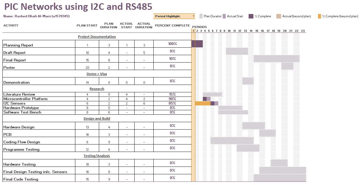
For a better understanding and clarity of organisation of work, work packages are categorised into main headings. These headings define key milestones or section of work in terms of work completion
(refer to Gantt chart from appendix).
Gantt Chart made for this project is tracked on a weekly basis. It is assumed that the total duration required will span over 23weeks. Most of the research work is carried out in the first 10 weeks of the project and remainder is used for design, implementation and build of the defined objectives. Detailed work package description is as follows:
1.4.1 Project documentation
This section will run throughout the length of the project and will be updated based on key deadlines i.e. submission dates. This mainly includes Planning report, Final Report and Poster. However, aim is to also produce draft reports where possible. The whole duration of which will be from start until the final submission.
1.4.2 Research
This work package has the most significance in the early stage of the project, as this will help in finding a direction. All other work packages like design and testing rely on this category. This will have an estimated duration of about 2-3months covering major decisions like choice of micro-controller platform, sensors, prototyping design and a strategy to write the code. Without having a clear guideline or research strategy in later stages will be affected heavily in terms of time scale. These delays will have impact on the overall planning as well as cost. Much emphasis is put in this section.
1.4.3 Design and Build
Following the research and completion of literature review, it should provide a clear path for hardware and software development. As this part of the project is heavily dependent on other factors such as parts availability, delivery, cost and most important of all their operations. Based on the review carried out in the earlier section if the devised methodology is incorrect then this will have an impact on design and build section. This section will also deal with software development which will be carried out over a time period of 12-14 weeks including testing. Once the code is tested and finalised the hardware design will be transferred on a PCB using KiCad or similar open source package. This build will be based on time taken by the lab to produce the board and building it by hand.
1.4.4 Testing and Analysis
Final section will involve rigorous testing of the developed hardware and software. This section is dependent on the previous section, as this cannot be continued without a fully designed and programmed sensor network. This will further include making sure all the hardware works without any electrical issues. In addition, software will be tested fully using different conditions. This will help verify any bugs in the software. All this will take up to around a total of 12weeks time once the design is completed.
1.4.5 Deliverables
- D1 – Embedded C code for PIC16F877A
- D2 – Design of a main board (PCB) based on PIC16F877A
- D3 – Design of multiple sensor boards (PCB) including temperature and humidity sensors.
1.4.6 Key Milestones
M1 – Hardware Selection and Order Placement
This Milestone is based on the preliminary investigation and a mutual decision with agreement of supervisor. Development will start based on this milestone.
M2 – Development of C code for the matrix multimedia development board
Initial development of a test environment where matrix multimedia board is connected with the acquired eblocks. MPLAB is installed and a basic interface is developed with the help of switches, LEDs and an LCD.
M3 – Sensor Networks using I2C protocol
Using the sensor eblocks and the I2C protocol a sensor network will be programmed using MPLAB/MikroC and PIC16F877A. This milestone will include completion of a software to communicate with the individual sensors, data acquisition and display on the main matrix multimedia board using an LCD module.
M4 – PCB Development
As a final milestone, a PCB will be designed with the sensor used on eblocks. Using the PIC16F877A microcontroller, a main PCB will be designed and will be connected to custom designed sensor boards.
Chapter 2
In this chapter, discussion about the previously set aim will be carried out. Main sections will include various communication protocols available within device-to-device communication. Later selection of Microcontrollers and overview of sensors will be presented.
2.0 Background
Specified in the introduction chapter, key feature of the project is to develop communication link between a microcontroller (MCU) therefore it is important to understand various types of MCUs available in the market and how are they different from each other.
This search can be divided in to two main categories. Development system and MCU on its own. With a lot of recent publicity and cheap prices to produce MCUs many companies have started to produce their own development kits. This is mainly to provide an easy start for beginners and to help them learn embedded programming. However, sometimes learning is not an objective and building a project is. For such approach, people do not require prior knowledge and like to just follow instruction and build a kit. Some microcontroller kits and devices are presented in the next section before deciding on the final one.
2.1 Selection of Microcontroller
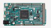
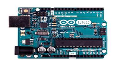
The two major suppliers of microcontrollers are ATMEL and Microchip. Microchip is famous for its standalone 8 and 16-bit PIC MCUs whereas ATMELs MCUs are famous because of the Arduino platform. (Arduino, 2017). This is because Arduino is created mainly by software and electrical engineers to provide an open source platform for those wishing to just use the MCU without knowing much about its fundamentals. Also the differences include the architecture as well as the peripherals i.e. GPIOs, timers, interrupts, memory etc. Arduino bootloader has many different MCUs available but their most famous ones are Arduino UNO, DUE, Nano and Mega. The two most common ones are listed below. (Quora, 2016)
| Uno (ATMEGA328P) | Due (SAM3X8E) |
| 8-bit | 32-bit |
| 16 Digital I/Os | 54 Digital I/Os |
| 4 Analogue Pins | 12 Analogue Pins |
| 16MHz clock frequency | 84MHz clock frequency |
| 32KB RAM | 512KB |
| 2KB SRAM | 96 SRAM |
| 5V input voltage at 50mA current consumption | 3.3-5V input voltage at 130mA |
The second important MCU is PIC16F877A from microchip. This microcontroller is an 8-bit MCU as seen in the diagram below. The PIC 8-bit family also has 18F and 24F series. A sample chart can be taken from microchips website, which provides parametric search as given below.
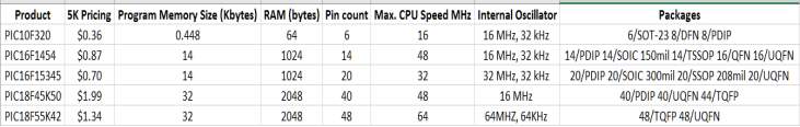
Similar to Arduino microcontroller various size microcontrollers are available from microchip as well. Their selection is mainly based on user application. They also come in big memory sizes as well as high clock speed. But with higher memory and clock speed the cost of the microcontroller also increases. Also to be noted is that these microcontrollers are in standard dual in line (DIL) packages and not like a development board like Arduino platform.
2.2 Communication
2.2.1 Communication between MCUs
For an easier understanding, we can consider computer networking as communication between devices. However, since sophisticated protocols such as TCP/IP are already implemented on the operating system and the network cards we use therefore, it is hard to imagine how the devices actually talk to each other. To understand this concept we need to understand how an MCU will establish communication with another MCU. This is essential when we have multiple MCUs responsible for doing various tasks while communicating with each other.
Device communication can be broken down in to two; wired and wireless. The traditional style of communication commonly seen in the form of a telephone was carried out using just two wires. This is the oldest form of wired communication and also reliable too. For complicated networks, there are certain rules of communication established by the regulatory authorities such as the IEEE (IEEE, 2018). These certain rules of communication are referred as protocols. These protocols were developed based on the infrastructures need and were improved based on industrial requirements. Most modern of these stood out to be serial communication compared to parallel. This was because parallel communication used more hardware than serial. Some of the most popular serial industrial standards include RS232, RS485, SPI, I2C, CANBus, MODBus, Ethernet and LIN. There are others as well that are used in manufacturing industry such as for PLC control and communication etc.
Also to mention are some wireless communication protocols that have evolved over the years including Bluetooth, Zigbee, Wi-Fi (TCP/IP), RF 433MHz etc. (IEEE, 2018)
2.2.2 Protocols
As described in the previous section many of the communication standards created are referred as protocols. In complex systems there can be multiple protocols. The communication between devices entirely depends on the end devices. In electrical systems their type can be determined based on the data that is flowing, the environment where the communication has to take place, how much the error in the communication can be avoided, how frequent is the communication going to happen. Also hardware is also an import part of the selection criteria. Within serial communication, few protocols are listed below to give an overview of the usability and implementation of each one of these.
2.2.3 RS232
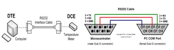 One of the earliest and the most popular device-to-device communication protocol has been RS232, also defined as “Interface between data terminal equipment (DTE) and data communications equipment (DCE) using serial binary data exchange”. As the official name suggest this type of communication was developed to establish connection between terminals and establish a digital communication using binary data exchange. The transmission in this protocol can be broken into STOP BIT, Parity Bit, 8-bit data, and then START bit. Usually only two wires are used namely transmission TX and reception RX. To create a common ground a GND wire is also used. There is no way to address device other than the Baud Rate. Both devices need to be on the same baud in order to communicate. There is also no sophisticated way to address multiple devices. Voltage levels determine the transmitted and received signal. A transmitted signal will have a Binary value 0 if the dc voltage is +5V to +15V and Binary 1 is -5 to -15V whereas, the received signal will be represented by Binary value 0 when the dc voltage is +3 to +13V and Binary 1 when the voltage levels are -3 to -13. The wiring schematic can be seen below. (OMEGA, 2018)
2.2.4 RS485
One of the main problems highlighted in the RS232 section includes communication with multiple devices. RS232 protocol is not capable of having multiple terminals connected together. This makes it almost impossible to develop a network because it only has one device. There are no simple or complex ways to have various devices talk to each other. It is easier to just have to connect a simple device in RS232 protocol but not possible to have multiple devices or sensors connected together. This problem is addressed in a relatively newer protocol the RS485. RS485 is also similar to the RS422 protocol which is a multi-drop protocol meaning multiple devices can be connected to it i.e. up to 32. Each port is then assigned a fixed address. Message sent from the terminal is heard by all the devices but only picked and responded by the main slave device. The host only has two wired TX and RX wires. The controllers can also talk to each other without any interruptions from the host. The main difficulty in implementing RS485 is its complex programming and a dedicated hardware. There needs to be a system which switches between transmitted and received signals as they both cannot be high at the same time. The wiring can be shown below. (Omega, 2018)
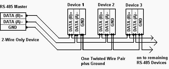
Figure 6 RS485 Schematic diagram (Omega, 2018)
2.2.5 SPI
One of the recently popular protocol is the Serial Peripheral Interface or more commonly known as SPI Bus. This serial bus interface is based on two-way communication for both sending and receiving data. Such type of communication is known as full duplex. This means that data is simultaneously sent and received at the same time. The most common way of implementing serial communication is to use master/slave configuration. This means that communication is set up by a master device which is responsible of requesting information from a slave device like RS485. This type of communication is also synchronous meaning that both master and slave needs to be on the same clock frequency. Having the same clock means that there is a dedicated physical pin that provides this purpose, SCK (Serial Clock). Further to clock pin, data lines are defined as MOSI (Master Out Slave In) to send data from the master or Receive pin for the slave device. Also for the slave device to send data MISO (Master In Slave Out) line used. So far the total number of pins become three. Since there can be many devices on the bus therefore a dedicated pin is used to first enable the slave and then request or send data to it. This line is referred as SS (Slave Select) or CE (Chip Enable) pin. The following diagram shows the schematic of a SPI bus. (Circuit Worx, 2017)
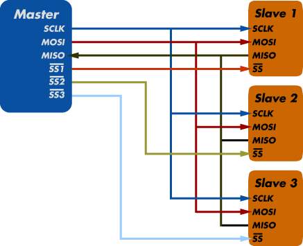
Figure 7 SPI Bus pin schematic (Phase, 2018)
2.2.6 I2C:
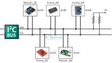
Another famous serial full duplex protocol is commonly referred as “I2C” or “I two C”. The actual name is Inter Integrated Circuit protocol. This protocol was developed by Philips in the early 1980s. After acquisition by NXP in 2006 this protocol is associated with NXP semiconductors. Compared to its counterpart protocols this protocol was aimed at making communication simplistic and faster. This requires a very low use of hardware and also simple software implementation. Like other communication protocols where either they are half duplex or require a separate hardware or even an extra pin are addressed in this protocol. Initially I2C provided speeds of 100kbit per second. Later this improved up to 3.4 Megabits, also further improvements include UFM or the ultra-fast mode. Like RS485 the bus only requires two lines SDA (Serial Data) and SCL (Serial Clock) clock and data. Also all the devices work as master and slave meaning they can talk to other devices on the network as well. Unlike RS232 no fixed baud rate is required. Addressing of the devices is done through the software so unlike SPI bus the device does not require a dedicated chip enable pin. This makes I2C a true multi-master bus. (I2C, 2017)
Chapter 3
3.1 Overall Hardwar Design
Understanding various design features of the project are important as they help in understanding the specifications. As part of good engineering practice the concept is transferred in to researching how to solve the problem and what are possible solutions to the problem. This approach is further used in hardware design section. Based on the work carried out in chapter 2, now components are decided and will be used in to designing a network. In chapter 2, we presented various microcontrollers and different types of communication protocols. In this chapter, one from the many protocols is selected and also a microcontroller is chosen to best suit the selected communication protocol.
Before the development begins, it is further important to decide how the system will be first developed and later tested. This is also part of the main project deliverables. To develop a system in a controlled environment it is vital to have a fixed hardware that will not fail during the development. Selection of this hardware is also described in a later section. At a small scale, showing how two devices can communicate there must be a use of low cost computer that is programmable but sufficient enough to produce the desired results. Discussion regarding microcontroller mentioned in the previous section is further extended in a later section of this chapter.
In order to avoid higher development cost slave device will be designed in this section. This will help understand the complexity of developing your own purpose built microcontroller based slave device. For this purpose, PCB design tool such as SoftCAD Eagle is utilised. This approach is very useful in project design where a test code is developed and tested on a fixed working hardware and is later transferred to a custom built PCB. Hardware is also kept modular in order to do easy fault finding. If a component fails during the development phase we can easily replace it. This saves both testing and development time. From programming perspective, a well-known platform is also used which is provided by microchip free of cost and another useful compiler by MikroElectronika. As recommended by the MCU manufacturer primary coding language used will be C.
To maintain compatibility, all the parts are purchased from the same manufacturer. Some of their devices are purpose built and compatible with the software. Furthermore, manufacturer also provides useful libraries or code in order to test the devices. In this project Matrix Multimedia development system along with Eblocks will be utilised. Also, since the aim is to develop a purposeful communication network therefore a sensor is also added on the slave device which will be updated occasionally to prove that communication is consistently happening and without any errors.
3.1.1 Matrix Multimedia Board (EB006-9)
One of the recommended development systems by Microchip includes Matrix Multimedia development system. This system is also used within my educational institutes such as University of Huddersfield. This development board is very versatile and is based around Microchip’s PIC 12F, 16F and 18F family devices. Not only can it feature these devices but also accepts various MCU packages such as 14, 28 and 40 pin MCUs. Furthermore, the board has a very good power management system in order to provide power to the main IC. It can be powered from both a USB Type-B connector and also using a power supply unit. Since there is a voltage regulation circuitry available on the board higher voltages cannot damage the MCU. Having a screw terminal on the side also means that power can be transferred on to other boards from one single power source. Another useful feature is to have a removable crystal on this board. By using this feature various frequency crystals can be used. It is normally shipped with 20MHz crystal which in our case is replaced with a 4MHz crystal. To programme this board separate programmer is not required. It has proprietary Ghost chip which communicates over USB with the provided software. This chip eliminates the need to buy another programmer. However, there is a separate header available on the board in order to programme from an external programmer. The thing that makes this a development board are its expansion ports and daughter boards. They are known as Eblocks. They connect with the main board using a 9-way D-type connector normally used for serial ports. Since there are only 8 bits on each port, therefore it is sufficient to use such a connector. PIC16F877A microcontroller has PORTA to PORTE. Next section describes various daughter boards and their use. (Matrixtsl, 2018)
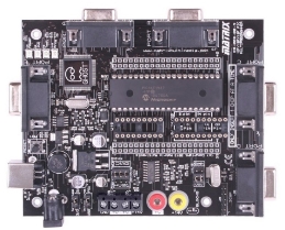
Figure 9 EB009 matrix multimedia main board (Matrixtsl, 2018)
3.1.2 Daughter Board (EB083)
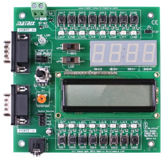
Matrix Multimedia supplies individual boards to be used with the main board. This ranges from simple toggle switches, LEDs, LCD, 7-Segment, Sensor, Actuator and communication boards. They have a variety of boards all available through their website. Since some of the basic components are necessary for any type of development therefore the created an all-purpose daughter board shown below.
From projects prototyping point of view this board is very useful since it is a simple one-board solution that contains all the needed features. It mainly contains the following features illustrated in the block diagram shown below.
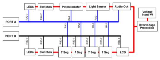
Figure 11 Eb083-02 block diagram (Matrix, 2018)
This board mainly utilises PORTA and PORTB. Some of the peripherals are connected to PORTB such as the LCD and 7-Segments. Both ports have their own LEDs and Switches which can be individually programmed. One thing to be noted here is that power available to drive the LCD is not sufficient since the LEDs and switches only work through the current available from the MCU. In order to make the LCD work an external power source must be connected. This can be taken from the main board’s screw terminal and connected to the input voltage terminal of the daughter board. The ground is already connected through the 9-way connector.
3.1.3 PICKit 3
After the development is finished a custom made daughter board will be made using PIC16F877A. Once the board is developed it should have the capability to be reprogrammable. This is important since during the programming phase many changes are made to and various tests will be carried out. To make slight changes it does not make sense to remove the MCU from the board plug it into the main board and programme it every time the code changes. This will make the system inefficient. For this purpose, an In Circuit Serial Programmer (ICSP) is used. This feature is available in many modern 8-bit microcontrollers. Another one of Microchip’s product is called a PICKit 3 programmer. This programmer can be used to programme any 8-bit PIC microcontroller (shown below). The following PIN diagram is used from the provided application notes. (Microchip, In-Circuit Serial Programming, 2017)
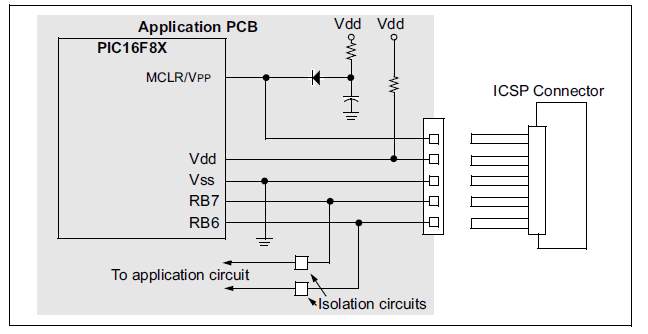
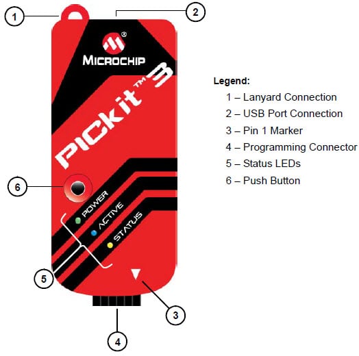
In comparison to the Ghost chip programming method PICKit 3 programmes the MCU quicker and can also be used with the main board.
3.1.4 The Sensors
Selection of microcontroller development system and the programmer now leads to the selection of the sensor that is going to be used with the slave board. There are many sensors available these days and are easily available too. However, their selection depends on many factors. One of the major factor in selection is their application, what is intended to be measured. Is it light, temperature, motion or acceleration? Once the application of the sensor is chosen then it’s interface is important. Which type of interface is available and how will it work with our choice of microcontroller? Similar to the device-to-device communication sensors come with various communication protocols as well. Some are simple analogue sensors which produce change in resistance and can be measured using an analogue to digital converter. Some however are digital sensors which require extra bit of programming in order to calculate the value. The clear advantage of using a digital sensor is that the readings are accurate and there is a very little chance of getting errors in the reading as the signal will not get corrupted. Following are selected sensors for the project.
Digital Temperature Sensor (DS18B20): One of the very popular temperature sensor in recent years has been the DS18B20 digital temperature sensor by Maxim. This tiny thermometer has many features and is considered very precise. The biggest advantage of this temperature sensor is that it is also known as one wire sensor meaning that it only requires one wire to communicate with the MCU. Furthermore, it has a unique 64-bit serial code therefore you can have as many temperature sensors as you like and request temperature value from the sensor you need. This temperature sensor has a range of -55°C to +125°C (-67°F to 257°F with an accuracy of ±0.5°C. This type of sensor is very much used in many temperature controlled applications. With it being a digital sensor it is reprogrammable. Also, it provides a programmable precision from 9 to 12bits. (Integrated, 2018)
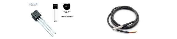
Figure 14 Dallas sensor schematic and housing
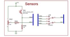
Further sensor available on the daughter board is a Light Dependent resistor (LDR) and a Potentiometer. The main role of this sensor is to provide measurement of light intensity. This is done through the change in physical property of the material when light falls on it. Since the resistance change cannot be measured directly therefore a potential divider circuit is made to draw current from the light dependent resistor. This is implemented on the daughter board as shown below.
- Further components as described in the previous section are used such as LEDs and switches. They are connected using current limiting resistors since the MCU can only provide up to 40mA of source current. The PCB will have three LEDs and switches.
3.1.5 MCU Pin Map for Slave
The only components that are left to be selected are the pins of the microcontroller that are going to be used on the slave board. Most of the PINs are already selected since they are fixed peripherals. One main advantage of using PIC 16F is that unlike RS485 it has a built-in I2C module available on PORTC. Therefore, the pins for this module are fixed. On the slave controller the only pins that are needed to be set include the LEDs, switches and the temperature sensor. They are shown in the table below.
| PIN | PORT | Connected To | Type/Direction | Description |
| 30 | RD7 | Switch 1 | INPUT | Momentary Switch |
| 24 | RC5 | Switch 1 | INPUT | Momentary Switch |
| 22 | RD3 | Switch 1 | INPUT | Momentary Switch |
| 37 | RB4 | LED1 | OUTPUT | Red LED |
| 35 | RB2 | LED2 | OUTPUT | Yellow LED |
| 34 | RB1 | LED3 | OUTPUT | Green LED |
| 23 | RC4 | SDA | Digital | Serial Data |
| 18 | RC3 | SCL | Digital | Serial Clock |
| 38 | RB5 | TEMP | Digital | DS18B20 Input |
Out of many ports available, only the above are used to have less hardware issues when designing the PCB. The switches can be used to request the temperature from the master or to set different threshold values for the temperature. The LEDs are added to the slave board so they can be used during the development phase as flags during testing. Later they can be utilised to show various errors or alert user.
3.2 Development Software
Once the hardware is finalised the final part of the development included making the software to be able to communicate with the devices. This is distributed into two main parts. One for slave and one for the master. Initially MPLAB X was used due to its ease of programming and familiarity but since making the project work in time was more important therefore libraries were used from MikroC. Therefore, using MikroC was the choice of development software in this project.
3.2.1 Integrated Development Environment (MikroC)
In order to programme the microcontroller there are various languages available such assembly, C, C++, Java and even python to name a few. The newer the language or higher the language the harder it gets to programme a controller easily. It is however easier to programme a microcontroller with higher-level language for a beginner using simple IDEs such as Arduino but the problem with such environment is that all the functions are premade. The programmer can hardly change anything because it is a readymade function. This can cause issues when we are trying to programme time critical or specific peripherals of a microcontroller. In this project prior knowledge was gained through the embedded systems module. Two compilers are famously used for this purpose, MPLAB X and MikroC. Both of these compilers come with their own features. MPLAB is an old compiler and has been used by educators and engineers for more than 30 years. Since MPLAB is designed and published by Microchip, who are also the manufacturers of the PIC microcontroller, makes MPLAB more suited for PICs. However, MPLAB has many advanced features and requires more than intermediate knowledge. Therefore, creating your own functions and library for a specific sensor can be very time consuming as the IDE is targeted towards professionals. Initial work is carried out in MPLAB and later for integration and final code, MikroC is used. MikroC is also based on similar structure like MPLAB but a lot of features are simplified as drop down menus. It also incorporates an extensive library already installed for sensors and other C language functions.
3.2.2 Eagle Cadsoft PCB Design Software
In any engineering project, a final product is mostly expected. Similarly, once the programming is done for the slave board it is part of the project deliverable to design and assemble a printed circuit board (PCB). Over the past few years there has been a lot work carried out to make computer-aided software (CAD) for PCB designing. One of which is very popular amongst hobbyists is called Eagle from Autodesk. This software is mainly famous because of its completeness. This means that you can make a schematic inside the software and transfer it to make PCB layout. Eagle is also widely used and accepted by PCB manufacturers including technicians in university’s lab. It easy to use but most importantly free to develop non-commercial educational projects. Once the layout is done, it can be sent to a manufacture for mass production. Further key features include open source library files, which are available for almost every component that is manufactured for electronics.
Chapter 4
In this chapter, main focus is on the development and final design of the main project. This is mainly divided in to two major sections, software and hardware. In this project the software has been more challenging then developing the hardware. However the complete code is available in the appendix for both master and slave device. In this chapter all the libraries and registers used are explained.
4.1 Setup
After selection of the pins, the I2C registers are located in the PIC16F877a board. The schematic diagram provided by microchip can be seen as follows. Main part of the project is to understand where the I2C peripheral is located inside the microcontroller and how can it be configured; all the important information is taken from the datasheet. The following block diagram is for the MSSP serial communication module present inside the PIC16F877a.
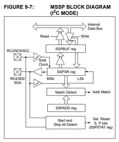
Figure 16 MSSP Module block diagram (Microchip, PIC16F87XA Data Sheet, 2017)
Looking at the above block diagram of the I2C module, there are further registers that require configuring. Both the clock pin and the SDA lines are controlled and linked through the SSPSR register. This register is also responsible for making sure the address bit matches with the slave. Before further looking into other registers, we need to check which registers which are involved in configuring the I2C bus. These are listed as follows:
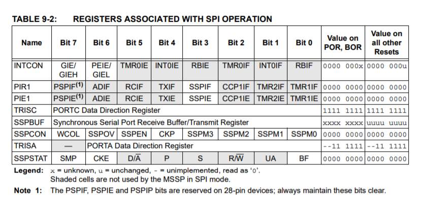
As shown in the above register, TRISC is the register which sets the direction for the SDA and SCL lines. Further important registers include SSPCON register, which has the I2C enable pin as well as sets the role of the module. Here the module can be setup as master or slave. Addressing of the slave is also setup in this register along with bus speed. After SSPCON the most important is the SSPSTAT register. This register holds the status of several bits or can be referred as flags register. These flags are set high or low based on their set functions. D/A, R/W and BF are the main flags that are used. Individual bits are described as shown below.
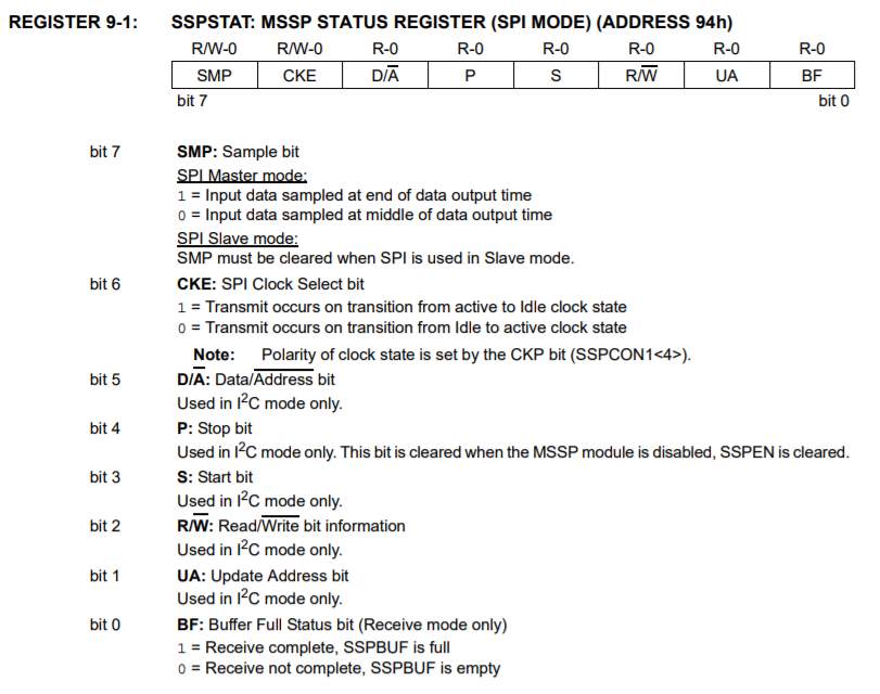
Figure 18 SSPSTAT Register (Microchip, PIC16F87XA Data Sheet, 2017)
D/A bit is used to confirm the address of the receiving data. R/W bits provides with the status whether it is a data read request or write. This bit is important since this tells the slave whether a write or read request has come from the master device. To finally check whether the data has been received BF bit is checked as this indicates buffer is full. Start and Stop bits are set high or low based on the timing of the transmission. At the beginning the Start bit is set high and after appropriate delays and message transmission Stop bit is set high. The sequence of this is provided in the data sheet application notes.
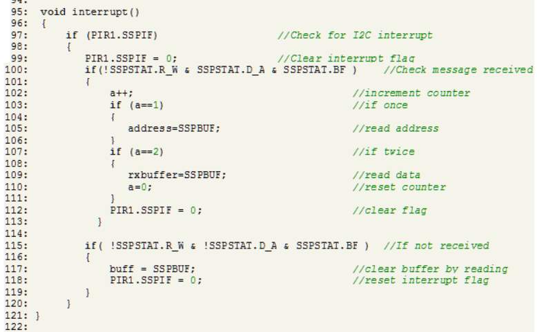
The message sent is available in the SSPBUF buffer register. This register holds the data. When the buffer is read the value held in the buffer is discarded or in other words the buffer is cleared. In any transmission the buffer is always read initially to make sure no error or gibberish data is present. On the second read, the actual data is passed to a global variable. For a more efficient implementation of the I2C bus, interrupts can be used. The I2C bus has its dedicated interrupt peripheral and a flag. Interrupt enable pin is found in the PIE1 register as SSPIE and the serial interrupt flag is present in PIR1 register as SSPIF. It can be used as any other interrupt present in PIC16F877a.
4.2 Libraries
In order to focus more on the implementation and avoid any configuration issues MikroC compiler was used with its premade libraries. These libraries were enabled in the library manager of the MikroC tab as shown below.
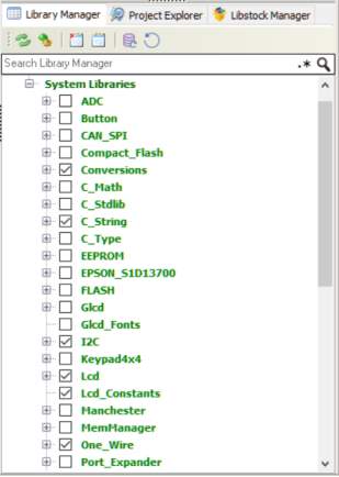
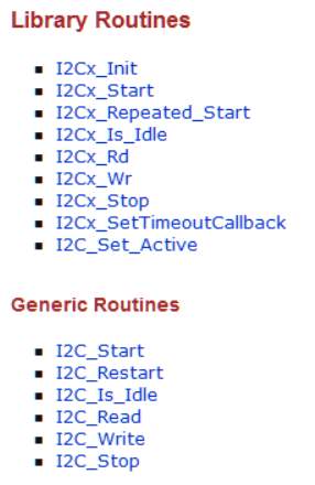
As can be seen above LCD and I2C libraries are the main libraries selected in order to configure the I2C bus. This is also to mention here that in MikroC it is simple to just select the desired library and the functions are made available without attaching any source or header files. Inside the I2C library these are following functions that are made using registers and bits mentioned in the previous section.
To simply set the parameters and the speed of the I2C bus I2C1_Init function is used. However other bits are used to form a full function in order to read and write from the I2C bus. This is shown in the later section.
The LCD library is also used within the master code to display the message on the LCD module available on the daughter board.
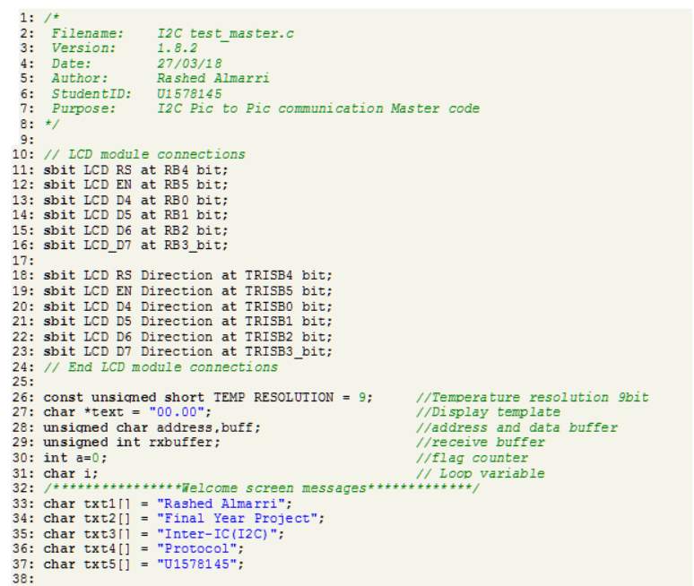
4.3 Master Code
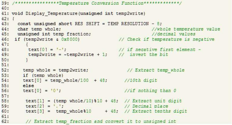
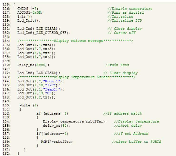
The master code comprises of different functions. The simplest of which is setting up the pins for the LCD module and initialising the LCD. Cursor, Write and various other functions are provided in the library. The master device in this project is used so it can provide conversion for the temperature as it is sent from the slave device. For this purpose, a display temperature function is also added. This function can take an integer as its argument and separates the tens, units, hundredths and thousandths from the reading value. After doing so, it combines all these digits inside any array and displays this on the LCD (refer to code in the appendix).
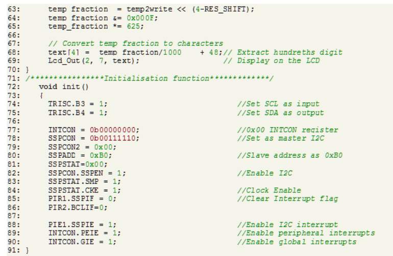
In the initialisation part of the code, the I2C bus is first initialised as mentioned in the setup section. Address of the slave is set as 0xB0 where the zero indicates read mode. The master code uses the Interrupt service routine to check if the message has arrived. SSPIF register is checked and R/W, D/A and BF bits are checked. If its read mode, address matches and the buffer is full then the SSPBUF is read and stored in to the global variable to be sent to the temperature conversion function. Whenever an interrupt occurs, the temperature is updated.
4.4 Slave Code
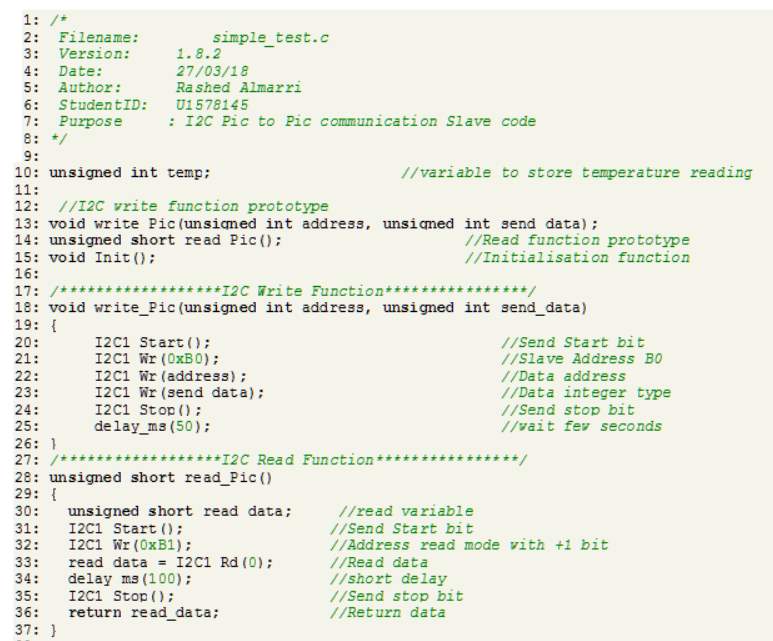
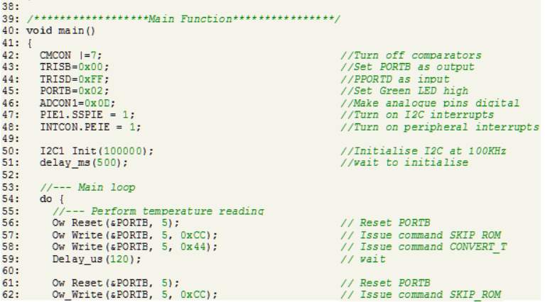
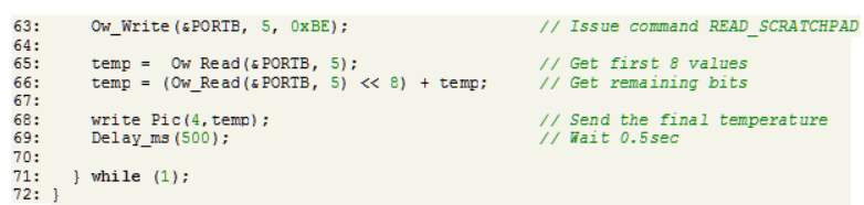
Slave code also uses the same libraries however; the functions developed for slave are simpler. The I2C bus is first initialised at 100KHz. Since we require the setup of the DS18B20 sensor One Wire library is used to setup the sensor. 9-bit data is read and stored. Since the registers are only 8-bit the bits are shifted and a 9-bit temperature value is made on every cycle. Using the write_pic() function the data is transmitted every 0.5 milliseconds. The slave code is set simplistic and main work is carried out in the master controller.
4.5 Hardware Setup
4.5.1 The Master Board
For the main development phase all the coding was carried out using the matrix multimedia board and the daughter board. As suggested in chapter 3 the boards are simply connected together and PORTs are configured accordingly. The LCD available on the version two board is a 4×20 LCD which is slightly different from the Hitachi LCD commonly used. This LCD provides more space for the display but has a different LCD library associated with it since the driver chip is different. PORTB and PORTA are used to check if the interrupt flag is working or not. A 9-way connector was used to connect the slave to the master board.
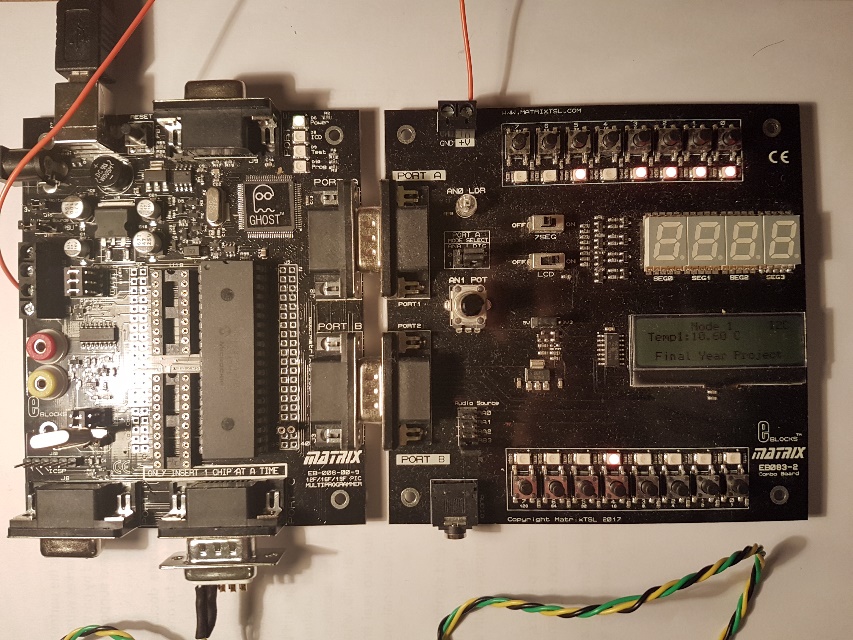 Figure 21 MAtrix multimedia main and daughter board
4.5.2 PCB Design
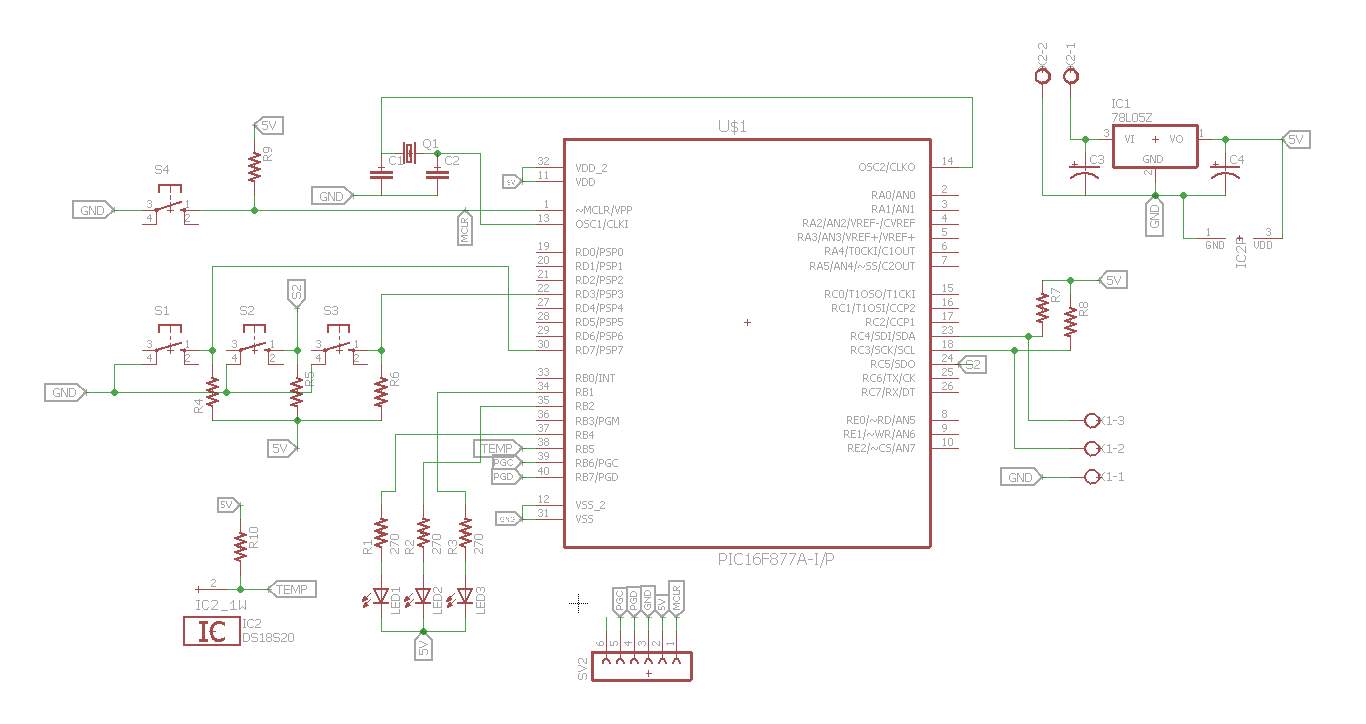 |
| PCB Schematic |
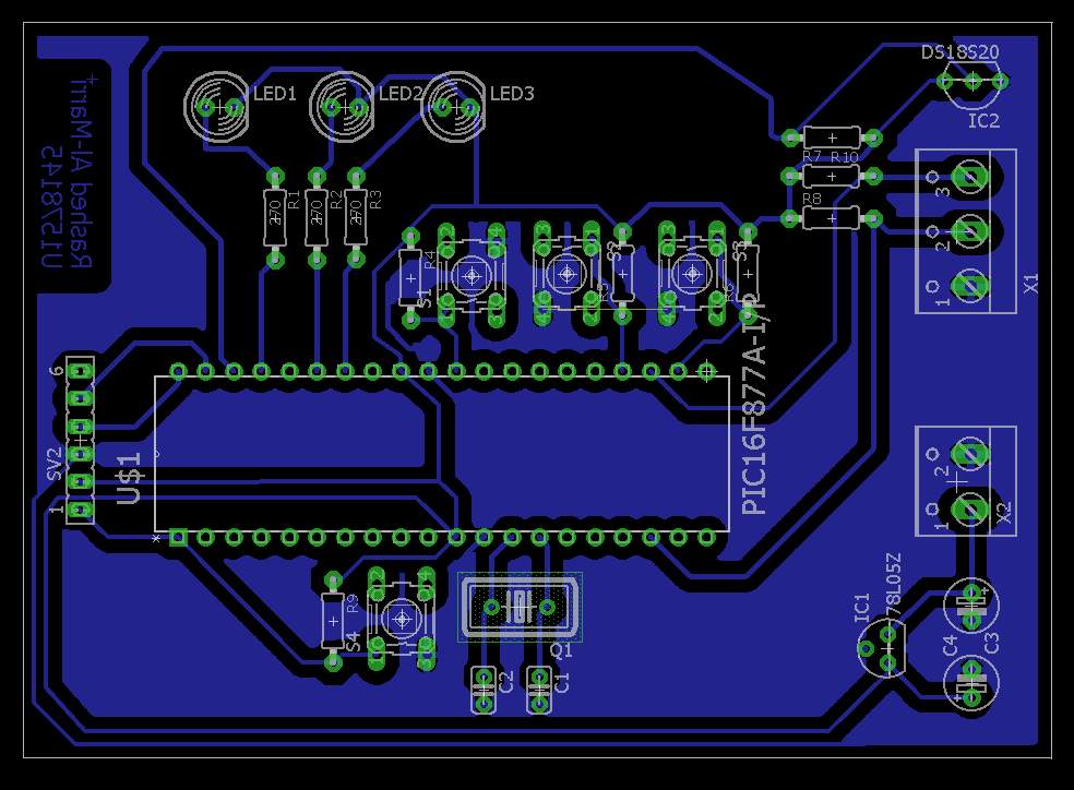 |
| PCB Layout |
PCB designing as mentioned in the previous section is divided in to two main parts. The first part deals with the schematic design of the desired circuit. As described in chapter 3 the pins are connected to peripherals based on the pin map provided. This is all done in Eagle software package.
Places where a connection could be made using a wire, a wire net was used and other places we used labels as they are considered internal connections. As can be seen there is also an ICSP header added to programme the MCU later.
From the schematic phase, the design is moved to layout where a CAD drawing is made of the final PCB and how it will look at the end. Since the lab requirement is to make a single sided board, therefore there are no double sided tracks. The blue area is common ground plane. The track width and spacing is done after consulting the lab technicians as an outside specification will mean that the PCB cannot be developed properly. All the components used are through hole.
Chapter 5
In this chapter, all the results are presented based on the work carried out in the previous chapter.
Main outcome of the project is has been the development of the PCB as it is seen in the picture below. The slave PCB is developed in the electronics lab and it was printed out without any manufacturing issues in the lab. Since the finishing is carried out by the developer the board is later drilled and the components are populated on the board. To check if the board was populated correctly the PicKit 3 programmer was connected and it worked.
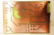 |
| Unpopulated PCB |
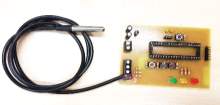 |
| Assembled PCB |
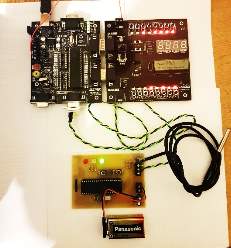 |
| Master Slave together |
Once the PCB was fully functional it was attached with the master board as can be seen above.
5.1 Analysis/Discussion
As part of the main outcome of the project both master and slave boards are programmed. Using the provided programmer and the MikroC IDE. There was a 9-way style D-type connector used to connect the slave board with the main board on PORTC. Using the schematic diagram from Matrix Multimedia RC3 and RC4 are located on the board. The wires were then soldered and connections were made.
An initial software was written to check if the I2C bus is working by sending simple binary data such as 1,2,4,16,32 and 64 by making the slave board as master and the Matrix board as slave. This data was received by the master board and sent to PORTB. The LEDs on the daughter board incremented in the right order. Using the switch on PORTB of the master board bit R/W was set so that the master can request data from the slave board. In the slave code, an interrupt was used during testing and the LED on slave board was toggled. Once this testing was successful then further development was carried on the slave board. Main objective at this point was to make the one wire temperature sensor to work on the slave board. A sample code was written in MikroC to read temperature from the DS18B20 sensor. Since there was no LCD on slave board therefore this code was first tested on Matrix Multimedia board and the temperature was displayed on the LCD. Once there were accurate temperature readings it was clear that the code is ready to be tested on the Slave board.
The indicator LEDs present on the slave board were programmed so they show the status of the board. Green LED shows that the board has power. To make a fair test the slave board is independent of the power from the master board. Therefore, a 9V battery is connected to the slave board to provide its own power. Since the MCU only operates at 5VDC therefore a voltage regulator is used to step down the 9V to 5V. On the slave board the resistors were used to limit the current for the LEDs and the switches.
Only the temperature was gathered from the sensor on the slave board. All the 8 bit data was sent to the master board. This method seemed useful, as this does not require a lot of code or configuration of the slave MCU. This technique is very useful as this also ensures that the data does not become corrupted and all the conversions take place in the master board. This also means that the slave board does not require a powerful MCU and instead only one master can be used with a powerful MCU. This will further reduce the cost. This method can also be seen as a fixed conversion point where slaves can send information to be converted and sent back to them from the master device.
Using the 4×20 LCD present on the daughter board, multiple messages such as presence of slaves on the bus and the connectivity with the bus were displayed. Any time a new temperature reading was present the LCD was updated with the new value. As soon as the wire was disconnected, the latest value was shown on the LCD until the wire was connected back for the new temperature reading. It was very robust and quick since interrupt was used. If the bus was polled every few seconds then this refresh method would have failed. Using interrupt ensures that the I2C bus does not need re initialisation and the master will not crash. This way even if one slave is offline others can still communicate with the master and keep sending data back and forth.
Chapter 6
6.1 Conclusion
All the major objectives set out in this project were successfully achieved. All the deliverables are set in the main chapter are successfully delivered. This included research of various device to device protocols. Understanding the complexity of implementing an I2C bus using PIC16F877A microcontroller. Furthermore, embedded code was written in C using MikroC IDE (code attached in appendix). One of the more challenging task of the project was to also design an example slave board and also make a PCB. This was done using Eagle software and a PCB was developed in the electronics lab.
The milestones set at the beginning of the project were very useful in tracking the progress of the project. Most of these milestones were achieved on time however there were some delays such as receiving the parts from Matrix Multimedia. This item was considered critical while making the project plan. Since delays are possible due to local holidays and part availability. Next major hurdle was the coding and switching between the two compilers. Initially the LCD library in MPLAB did not work for the LCD provided on the daughter board. This was due to a difference of LCD drivers. The provided LCD driver file used in embedded systems module was not compatible with this new LCD therefore moving from MPLAB was necessary. However, based on the example codes given by microchip for I2C MPLAB was used to test the slave and the master board. Since the LCD did not work using MPLAB, LEDs were used to indicate interrupts and messages.
Successful test developed confidence using MPLAB but due to time constraints it was wiser to move to MikroC to further develop the code with compatible LCD drive files. While working with MikroC I2C library was also used as this helped speed up the debugging and testing phase of the project. During the development a lot of testing was carried out to make sure the code delivers as set out in the objectives. Initially multiple nodes and sensors were to be used. But since most of the time was used in the understanding of the code and make one node work it was important to complete the project with a working code therefore only one successful and working node was created in this process. The total project cost worked out to be £225.18. Major cost incurred was due to the development board and the programmer (see appendix). However, these are one off costs meaning they are only to be invested in once. After the successful completion of the project, some future recommendations are made as follows.
6.2 Further Work
6.2.1 Add More Sensors
In order make the system more versatile more sensors should be added to each node in future such as Humidity, Light and motion sensor.
6.2.2 Add more features to the Slave
Since there are buttons and LEDs available on the current PCB design of the slave board more features can be added. These features can be an LED warning system where temperature thresholds are set to light up the LEDs. In addition, the buttons should be used to request temperature or turn off the slave when not needed. This can also be used to wake up the master device if it goes into sleep mode.
6.2.3 Add Multiple Nodes
Not only multiple sensors but also multiple nodes can be added to this network. To make the network versatile various microcontrollers of different types can also be used to run on the same network. Multiple master devices can also be added.
6.2.4 Robust Packaging or Enclosure
Finally, to protect the slave board it can be put inside a robust enclosure appropriate for the sensor.
References
Arduino. (2017, 04 22). Arduino Board DUE. Retrieved from Arduino: https://www.arduino.cc/en/Main/ArduinoBoardDue
Arduino. (2017, 04 22). Arduino UNO. Retrieved from Arduino: http://www.arduino.org/products/boards/arduino-uno
Arduino. (2017, 04 12). Home. Retrieved from Arduino: https://www.arduino.cc/
Circuit Worx. (2017, 03 29). Technology Introduction: Communications Protocols > SPI, I2C, I2S. Retrieved from CircuitWorx Electronic & Software Design: http://www.circuitworx.co.uk/communication-technologies/spi-i2c-i2s/
Edvard. (2016, December 7th). Correct Cabling of Modbus and RS485. Retrieved from Electrical Engineering Portal: http://electrical-engineering-portal.com/correct-cabling-modbus-rs485
Electronics, L. a. (2018, March 3). How to connect a In-Circuit Serial Programming (ICSP) interface? Retrieved from Learning about Electronics: http://www.learningaboutelectronics.com/Articles/How-to-connect-an-ICSP-interface.php
Electronics, M. (2018, January 19). Microchip Technology PICKit 3 Programmer/Debugger. Retrieved from Mouser: https://www.mouser.com/new/microchip/microchip-pickit-3-programmer-debugger/
I2C. (2017, December 13). I2C-What’s That? Retrieved from I2C-bus: https://www.i2c-bus.org/
IEEE. (2018, February 12). Wired and Wireless Communications Standard. Retrieved from IEEE Standards Association: https://standards.ieee.org/findstds/standard/wired_and_wireless_communications.html
Integrated, M. (2018, April 09). DS18B20. Retrieved from Maxim Integrated: https://datasheets.maximintegrated.com/en/ds/DS18B20.pdf
Matrix. (2018, Feb 24). Eblocks Combo Board. Retrieved from Matrix Tsl: http://www.matrixtsl.com/resources/files/datasheets/EB083-30-1.pdf
Matrixtsl. (2018, March 10). What are E-blocks? Retrieved from Matrix TSL: https://www.matrixtsl.com/eblockslegacy/
Microchip. (2017, October 30). In-Circuit Serial Programming. Retrieved from Microchip: http://ww1.microchip.com/downloads/en/DeviceDoc/31028a.pdf
Microchip. (2017, November 05). PIC16F87XA Data Sheet. Retrieved from microchip: http://ww1.microchip.com/downloads/en/DeviceDoc/39582b.pdf
Omega. (2018, January 25). RS485, RS422 and RS232. Retrieved from Omega.co.uk: https://www.omega.co.uk/techref/das/rs-232-422-485.html
OMEGA. (2018, January 19). The RS-232 Protocol. Retrieved from Omega.co.uk: https://www.omega.co.uk/temperature/z/rs232standard.html
Phase, T. (2018, Feburary 05). SPI Background. Retrieved from Total Phase: https://www.totalphase.com/support/articles/200349236-SPI-Background
Quora. (2016, November 13). What is the difference between PIC, AVR, ARM and Arduino Microcontrollers? Retrieved from quora.com: https://www.quora.com/What-is-the-difference-between-PIC-AVR-ARM-and-Arduino-Microcontrollers
Spark Fun; Mikegrusin. (2017, April 2). Serial Peripheral Interface (SPI). Retrieved from Sparkfun Start Something: https://learn.sparkfun.com/tutorials/serial-peripheral-interface-spi
Ward, D. D. (2017, November 27). I2C for arduino. Retrieved from Super House: https://www.superhouse.tv/i2c-for-arduino/
Appendix
a. Master Code
b. Slave Code
c. Gantt chart
d. Costing
| Item | Unit/Price | Total |
| Matrix Multimedia Board (EB009) | £132.62 | £132.62 |
| Extended E-Block EB083-02 | £65.00 | £65.00 |
| DS18B20 | £1.52 | £3.04 |
| PIC16F877A | £0.89 | £1.78 |
| Printed Circuit Board | £3 | £3 |
| Buttons | £0.18 | £0.54 |
| LEDs | £0.10 | £0.30 |
| Male D-type connector | £1.50 | £1.50 |
| Screw Terminal | £0.35 | £0.70 |
| PicKit 3 | £16.70 | £16.70 |
| Total | £225.18 |
Cite This Work
To export a reference to this article please select a referencing stye below:
Related Services
View all


Related Content
All TagsContent relating to: "Information Systems"
Information Systems relates to systems that allow people and businesses to handle and use data in a multitude of ways. Information Systems can assist you in processing and filtering data, and can be used in many different environments.
Related Articles

DMCA / Removal Request
If you are the original writer of this dissertation and no longer wish to have your work published on the UKDiss.com website then please: