PLC Strategies for Automatic Mixing and Bottle Filling
Info: 8343 words (33 pages) Dissertation
Published: 21st Jan 2022
Tagged: Information SystemsSupply Chain
Abstract
The goal of this work is to utilize the PLC strategies for atomization of modern item assembling to accomplish high throughput and enhanced quality and consistency. This technique incorporates putting bottles onto a transport line and filling bottles each one in turn. Filling is controlled by PLC (Programmable Logic Controller) utilizing step rationale technique. In the jug filling framework the PLC gets the sensor input and controls the solenoid valve timing and in addition controls the transport line. By programming the PLC, the whole framework is being controlled. Sensor remains as the most critical part for bottle filling.
Regularly in all robotization ventures, PLC is considered as the core of any framework Software approval and equipment execution utilized for showing the simplicity of task with this control alongside tuning of the whole framework for the three applications are exhibited. The outcomes from programming and exploratory setup are given framework equipment and programming points of interest alongside the understanding between tally of aggregate time taken for every task and the time set in program.
The confirmation of the rationale is done utilizing Ladder chart and in view of this rationale equipment has been executed. The outcomes from programming and exploratory setup are given framework equipment and programming points of interest alongside the assent ion between check of aggregate time taken for every activity and the time set in program. The whole framework is made more adaptable, efficient and easy to use. Each outcome prompts the conclusion that the activity of PLC in is exceptionally rousing.
CONTENTS
Click to expand Contents
Chapter 1: Introduction
1.1 Overview
1.2 Methodology
1.3 Problem statements
1.4 objective of the projects
1.5 scope of the projects
1.6 feature of the proposed system
Chapter 2: Design and Implementation
Chapter 3: Programmable logic controller (PLC)
3.1 Overview
3.2 PLC compare with other control system
3.3 Block diagram of PLC
3.3.1 I/O Module
3.3.2 CPU (central processing unit)
3.3.3 Program Memory
3.3.4 Power Supply
3.4 Mitsubishi PLC FX3G
3.4.1 Special feature of Mitsubishi PLC FX3G
3.4.2 Feel our quantity
3.4.3 Simple framework combination
3.4.4 Simple development
3.5 PLC Interfacing with PC
3.6 Communication
Chapter 4: PLC Programming with Instruction
4.1 introduction
4.2 ladder language
Chapter 5: IR Sensor
5.1 Working principle
5.2 The feature of the Sensor
Chapter 6: Relay
Chapter 7: Solenoid Valve
7.1 Working principle of solenoid valve
7.2 Different parts of a solenoid valve
Chapter 8: Conveyor Belt
8.1 Principle of conveyor belt
8.2 Benefits of conveyor belt
List of Figures
Fig. 2.1 Block diagram of the system
Fig. 2.2 Automation mixing of different liquids and filling
Fig. 3.1 Block diagram of PLC
Fig. 3.2 Mitsubishi FX3G PLC
Fig. 5.1 Functional diagram of IR Sensor
Fig. 5.2 IR Sensor
Fig. 6.1 Relay
Fig. 7.1 Functional diagram of solenoid valve
Fig. 7.2 solenoid valve
Fig. 8.1 Conveyor Belt
Chapter 1: Introduction
1.1 Overview
Computerization is utilized for all control frameworks and the advances in PLC is used to decrease the human work and aides in expanding the generation. PLC assumes a vital part in the realm of robotization industry. It acts a noteworthy capacity in the robotization field which has a tendency to diminish the intricacy, expands security and cost proficient. In this framework we have connected a PLC based control framework in a programmed bottle filling station. Mechanization is making the procedures programmed. It is the technique for utilizing control frameworks to work and control the working of modern handling innovation.
Mechanization can be found in businesses like steel processing plants, sustenance and drink ventures logical robotization et cetera. One of the control frameworks is Programmable Logic Controller, PLC, or programmable controller, utilizing advanced PC for computerization of normally mechanical electromechanical procedures, for example, control of apparatus on processing plant sequential construction systems, beguilement rides, or light installations. In little ventures bottle filling task is done physically. The manual filling process has numerous weaknesses like spilling of water while filling it in bottle, break even with amount of water may not be filled, delay because of common exercises of human and so forth.
This issue looked by little enterprises constrains us to take up this undertaking. It makes utilization of sensors for isolation and coordinating of the materials is controlled by utilizing engine and the transport line contingent upon the directions determined in the stepping stool rationale in PLC. In nourishment bundling industry PLC is essentially utilized for robotization reason which helps in decreasing bundling time and builds the generation rate as contrasted and manual framework. The acquired electrical flag is passed to PLC machine which contains the stepping stool outline of the circuit which holds the predetermined guidelines of the framework in interior stockpiling. Thus the framework is completely mechanized without manual mediation.
Another use of PLC can be found in programmed fluid blending and container filling industry. PLC can be customized utilizing stepping stool rationale, Boolean dialect and useful outline. Our venture is implied for little enterprises. It plans to take out issue looked by little scale bottle filling framework. With this framework that works consequently, every procedure can be smooth and the way toward refilling can lessen specialist’s cost and task time. The framework works by the program that intended to do the activity.
1.2 Methodology
There are three compartments, first holder contains shading 1 fluid, second compartment contains shading 2 fluid with the individual solenoid valve associated on it, and center compartment is blending and filling holder. Blending holder associated with a solenoid valve and a level sensor to detect the water level in it. At the point when the level sensor moves from NO contact to NC contact the transport line (i.e. DC Motor) begins pivoting. Thereafter the container is set on the transport then nearness sensor 1 detects the jug and transport line stops underneath the solenoid valve 3.Then there will be postponement of 5 seconds, after this solenoid valve open and begins filling the jug for 15 seconds, following 2 second of defer filled jug will advance on transport framework till the closeness sensor 2 detects the jug. After this the procedure proceeds till the stop switch isn’t squeezed.
1.3 Problem Statement
This machine is intended to consolidate the filling and topping procedure in a solitary machine. This undertaking will lessen the utilization of labor since the greater part of the work will be finished by machine. Human held filling procedure will cause estimated volume of fluid into the container. So utilizing mechanized framework will set the volume of the fluid precisely the same for each container. Human can’t give the enough strain to top the container, so it will utilize the high weight instrument to press the top on the jug. On the off chance that all the procedure is done physically, it will cost part of time to finish the undertaking. This machine will likewise lessen the human blunder while doing this procedure physically.
1.4 Objectives of the Project
- The task is expected to meet the accompanying destinations:
- To plan and actualize computerized filling and blending machine.
- To take in the idea of pneumatic framework, electrical DC engine framework.
- To actualize equipment establishment, wiring, mechanical mounting.
- To get the hang of investigating and examining.
- To learn PLC programming.
1.5 Scope of the Project
- All tasks have their own degree or confinement as a rule all through the consummation of the undertaking. The task scope for the usage of this undertaking is:
- Design and build up the entire robotized framework that is use to apply the filling and topping framework in term of equipment and programming improvement.
- The equipment improvement and usage comprise of mechanical structure, dc engine electrical framework, pneumatic framework, PLC and detecting gadget. The PLC will be the fundamental controller for the framework.
- The programming or programming improvement and usage.
1.6 Features of the Proposed System
- Our proposed framework has the accompanying highlights:
- Detection of the nearness of a jug utilizing sensor
- Timer based programmed bottle filling
- Control of the fluid level of the overhead tank
Despite the fact that this kind of PLC controlled frameworks as of now exist in the enterprises, however we got profitable handy experience on the most proficient method to outline a genuine mechanical framework and control a procedure utilizing PLCs while outlining and executing the undertaking.
Chapter 2 : Design and Implementation
This segment gives the usage points of interest of models which are utilized for modern applications. The models talked about are programmed blending and container filling framework.
Programmed blending and container filling framework utilizing PLC has been displayed. There are two destinations to be accomplished in this venture.
- To build up a program utilizing PLC for programmed blending and container filling.
- To create and plan a programmed blending and jug filling framework, the model must lessen the human mediation in the procedures.
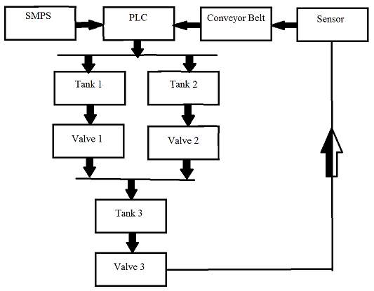
Fig 2.1 block diagram of system
Figure demonstrates the model of the proposed work for blending of water and proteins utilized as a part of drinks and squeeze industry. Here the sensor yield is contribution to the PLC and yields of PLC controls the valves, blender and transport line. In programmed blending and jug filling framework, at first two fluids specifically water and protein fluid from two unique holders are to be blended in a blending compartment. The blended arrangement is to be filled in the containers one by one. The entire framework must be begun by ‘S1’ begin catch. The main fluid (water) needs to stream in to the blending holder for 10 seconds. So also second one (Protein fluid) needs to stream into the blending holder for 15 seconds. The blending activity needs to occur for 20 seconds. When blending activity finishes, filling of each container needs to occur for 15 seconds. The required segments are as given underneath:
- Programmable rationale controller for building up the product/Logic to programmed entire framework.
- Containers to store fluids.
- Conveyor belt framework for bottle filling process.
- DC engine for blending activity.
- Sensors and transfers to recognize the jug.
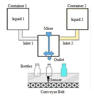
Fig 2.2 automatic mixing of different liquids and filling
Chapter 3: Programmable logic controller
3.1 Overview
These days, PLC is generally utilized as a part of uses of advanced world which is connected at the modern part. Typically, the PLCs have been utilized as a part of the modern field, to control a mechanical development, both of the machine or substantial machines for effective generation. The successive tasks and rehashed activities in businesses is ordinarily completed utilizing PLC. In Food and refreshment ventures, bottle rounding assignment is completed by a machines as manual filling process has numerous inadequacies for case spilling of water while filling it in bottle, break even with amount of water may not be filled, delay because of common exercises of human and cleanliness conditions.
3.2 PLC compared with other control system
PLCs are very much adjusted to a scope of computerization assignments. These are regularly modern forms in assembling where the cost of creating and keeping up the robotization system is high with respect to the aggregate cost of the mechanization, and where changes to the framework would be normal amid its operational life. PLCs contain info and yield gadgets perfect with modern pilot gadgets and controls; minimal electrical plan is required, and the outline issue fixates on communicating the coveted grouping of tasks. PLC applications are regularly exceedingly redone frameworks, so the cost of a bundled PLC is low contrasted with the cost of a particular custom-constructed controller plan. Then again, on account of mass-delivered merchandise, modified control frameworks are practical. This is because of the lower cost of the parts, which can be ideally picked rather than a “nonexclusive” arrangement, and where the non-repeating designing charges are spread more than thousands or a large number of units.
A microcontroller-based outline would be suitable where hundreds or thousands of units will be created thus the advancement cost (plan of energy supplies, input/yield equipment and important testing and accreditation) can be spread over numerous deals, and where the end-client would not have to adjust the control. Car applications are an illustration; a large number of units are manufactured every year, and not very many end-clients change the programming of these controllers. Be that as it may, some claim to fame vehicles, for example, travel transports monetarily utilize PLCs rather than hand crafted controls, on the grounds that the volumes are low and the improvement cost would be uneconomical.
PLCs may incorporate rationale for single-variable input simple control circle, a relative, essential, subsidiary (PID) controller. A PID circle could be utilized to control the temperature of an assembling procedure, for instance. Verifiably PLCs were normally designed with just a couple of simple control circles; where forms required hundreds or thousands of circles, a dispersed control framework (DCS) would rather be utilized. As PLCs have turned out to be all the more intense, the limit amongst DCS and PLC applications has turned out to be less unmistakable.
PLCs have comparable usefulness as remote terminal units (RTU). A RTU, nonetheless, generally does not bolster control calculations or control circles. As equipment quickly turns out to be all the more capable and less expensive, RTUs, PLCs and DCSs are progressively starting to cover in obligations, and numerous merchants offer RTUs with PLC-like highlights and the other way around. The business has institutionalized on the IEC 61131-3 useful piece dialect for making projects to keep running on RTUs and PLCs, albeit about all merchants additionally offer exclusive options and related advancement conditions.
3.3 Block diagram of PLC
- Input and Output module
- CPU (central process unit)
- Program memory
- Power supply
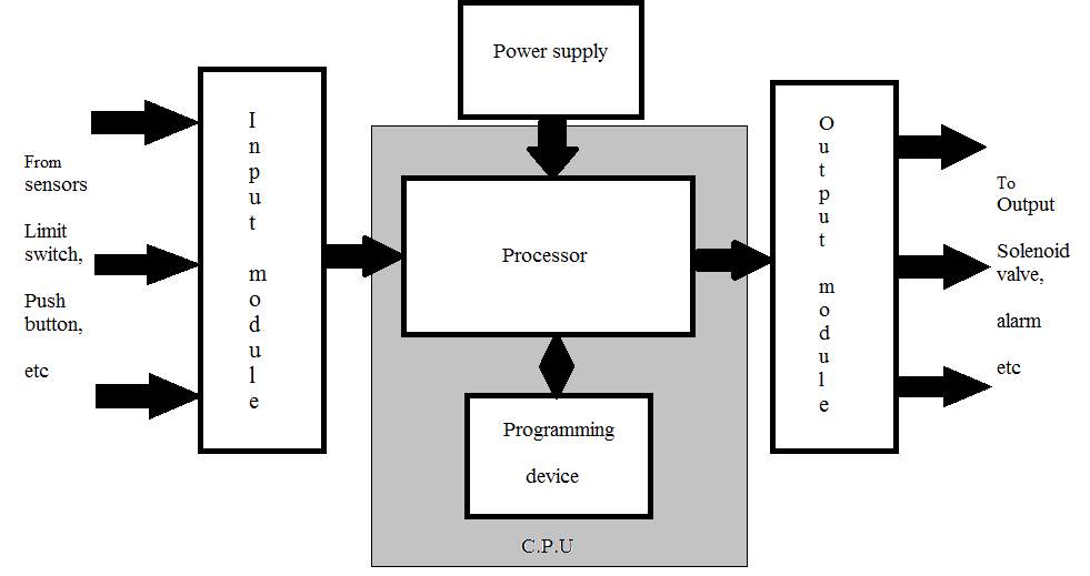
Fig 3.1 block diagram of PLC
3.3.1 Input and Output module
The I/O area set up the interfacing between physical gadgets in reality outside the PLC and the computerized field inside the PLC.
The info module has bank of terminals for physically associating input gadgets, similar to push catches, restrain switches and so on to a PLC. the part of an info module is to decipher signals from input gadgets into a frame that the PLC’s CPU can get it.
The Output module likewise has bank of terminals that physically associate yield gadgets like solenoids, engine starters, showing lights and so forth to a PLC. The part of a yield module is to decipher signals from the PLC’s CPU into a frame that the yield gadget can utilize.
The assignments of the I/O area can be delegated:
- Conditioning
- Isolation
- Termination
- Indication
An electronic framework for interfacing I/O modules to remotely found I/O gadgets can be included if necessary. The genuine working procedure under PLC Control can be a great many feet from the CPU and its I/O modules
Input module:
There are two types of input modules
- Digital inputs
- Analog inputs
1. Digital inputs
These convert the external binary signal from the process to the internal digital signal level of programmable controller.
Digital Input devices
- Switches
- Photo sensor
- Push button
- Limit switch
- Proximity sensor
- Limit switch
2. Analog inputs
Analog inputs cards converts’ continuous signal via a analog to digital converter into discrete values for the PLC Analog inputs devices
- Pressure transmitter
- Thermo couples
- Flow transmitter
- Level transmitter
- Load cell
Output modules:
There are two types of input modules
- Digital outputs
- Analog outputs
1. Digital outputs
These convert the internal signal level of the programmable controller into the binary signal level required externally by the process.
Digital outputs devices
- Solenoid value
- Led
- Coilers
- Relay
- Contractor
2. Analog outputs
Analog outputs cards converts’ digital values in the PLC to converts continuous signals via a digital to analog converts.
Analog outputs devices
- Flow control values
- Pressure control values
- Drive inputs
- Values
- Analog ports
3.3.2 CPU (Central Processing Unit)
The CPU is the cerebrum of the framework. The CPU is an extremely microchip based framework that replaces control transfers, counter, clocks and sequencers. A processor seems just once in a plc and it can be either a one piece (or) a word rationale activity. PLCs with word processors are utilized when handling content and numerical information, figuring’s, measuring, controlling and recording and in addition the basic preparing of signs in paired code are required. The CPU acknowledges (peruses) input information from different detecting gadgets, executes the put away client program from memory and sends proper summons to control gadget. An immediate current (dc) source is required to deliver the stream level voltage utilized by the processor and the data sources and yields modules.
This power supply can be housed in the CPU unit (or) might be an independently mounted unit relying upon the PLC framework producer. The vast majority of the CPUs contain the reinforcement batteries that keep the working project away in case of a plant control disappointment.
The processor memory module is a noteworthy piece of the CPU lodging. Memory is the place the control design or program is held or put away in the controller the data put away in the memory identifies with the way the information and yield information ought to be handled. The measure of memory required depends on the multifaceted nature of the program. Memory components store singular snippets of data called bits (for twofold digits).
The main purpose of the CPU is “scanning”. It performs the three main functions like
- Read the inputs
- Depends up on reading executes
- Return to the values of the output
These three capacities done at the same time by the CPU called CPU examine cycle. The time required to finish the just a single cycle is called “CPU examine time”. The CPU examine time relies on our rationale. In the event that the sweep time is increment the plc speed diminishes. In the event that the sweep time is diminishes the plc speed increments.
1. CHECK INPUT STATUS (read the data sources)
Initially the PLC investigates each contribution to decide whether it is on or off. At the end of the day, is the sensor associated with the primary contribution on? , Then the second info? , Then the third et cetera… It records this information into its memory to be utilized amid the following stage.
2. EXECUTE PROGRAM (depends up on perusing executes)
Next the PLC executes your program one direction at any given moment. Possibly the program says that if the principal input was on then it should turn on the main yield. Since it definitely knows which inputs are on/off from the past advance it will have the capacity to choose whether the primary yield ought to be turned on in view of the condition of the principal input. It will store the execution comes about for utilize later amid the following stage.
3. Refresh OUTPUT STATUS (come back to estimations of the yield)
At long last the PLC refreshes the status of the yields. It refreshes the yields in view of which inputs were on amid the initial step and the consequences of executing your program amid the second step.
Processor
The processor, the heart of CPU is the computerized part of the CPU in the form of Microprocessor / Micro controller chip. It supervises all operation in the system and performs all tasks necessary to fulfill the PLC function.
- It reads the information i.e status of externally connected input devices with input module.
- It stores this data in memory for later utilize.
- It completes scientific and rationale tasks as determined in application program.
- After solving the user’s program, it writes the result values in the memory.
- It sends data out to external devices like output module, so as to actuate field hardware.
- It performs peripheral and external device communication.
3.3.3 Program memory
Memory can be ordered into voltaic and non unstable and non unpredictable memory. Unstable memory will lose its put away data if all working force is lost (or) evacuated. Unstable memory is effortlessly modified and very reasonable for most applications when bolstered by battery reinforcement. Non unstable memory can hold put away data when control is evacuated coincidentally or purposefully. Plc makes use of many different types of volatile and non volatile memory devices.
- RAM: Random access memory (RAM) is composed so data can be composed into (or) read from the memory the present controllers utilize the CMOS-RAM with battery bolster for client program memory. Smash gives a superb means for effortlessly making and modifying an issue.
- ROM: Read-just memory (ROM) is planned with the goal that data put away in memory can be perused and can’t be changed under common conditions.
- EPROM: Erasable customized read just memory (EPROM) is outlined so that it can be reinvented in the wake of being completely deleted with the utilization of a bright light source.
- EEPROM: Electrically erasable customized read-just memory. (EEPROM) is a non unstable memory that offers the same customized adaptability as rams. It gives perpetual capacity of the program however can be effortlessly changed utilizing standard programming gadgets.
3.3.4 Power Supply
Here the power supply is independently specify in light of the fact that for plc to control up it requires just 24v dc in this way, to change over 230v air conditioning to 24vdc one converter is utilized called SMPS(switch mode control supply). The power supply gives energy to memory framework, processor and I/O Modules.
- It changes over the larger amount AC line Voltage to different operational DC esteems.
- For electronic circuitry.
- It channels and controls the DC voltages to guarantee appropriate PC tasks.
3.4 Mitsubishi PLC FX3G
3.4.1 Special feature of Mitsubishi plc FX3G
- Applies the demonstrated FX3G configuration to littler yet execution basic applications.
- Change it up of capacities to suit particular application needs.
- Expands on existing FX arrangement equipment and programming for snappy reception and speculation security.
- Coordinate control of inverter and movement control frameworks with no additional equipment.
3.4.2 Feel our quality
Mitsubishi Electric is the undisputed world driving provider of smaller PLCs. We originated the idea of this sort of controller more than thirty years prior. Our worldwide introduced base surpasses 9 million frameworks and our philosophy of tuning in to client needs protects this base keeps on developing. The presentation of the FX3U PLC set another benchmark for execution and adaptability in the minimized PLC market and we have kept on enhancing. The outcome is the FX3G, our new response to applications nee-ding FX3U like capacities in littler scale frameworks.
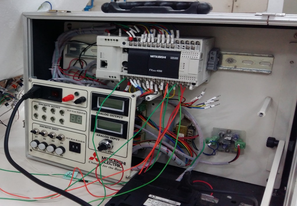
Fig 3.2 Mitsubishi FX3G PLC
3.4.3 Simple framework combination
The FX3G can work as an independent controller yet for when mix with other framework segments is required, a scope of standard highlights influences it to emerge from the group. Mitsubishi works in standard guidelines that allow simple control of our inverters over an exact, solid advanced connection. This makes it easy to interface an inverter, for example, a FR-D700 to give more exact engine activity while improving vitality utilize.
3.4.4 Simple development
With regards to expanding the capabilities of a FX3G, we broaden your alternatives while securing your abilities and contribute ments. The double transport engineering gives twice the same number of development conceivable outcomes com-pared to past outlines. On one transport, the FX3G utilizes extra, commonplace FX family I/O and exceptional capacity squares to mix it up of I/O and unique function abilities, for example, simple and systems administration. On the other framework transport, the FX3G utilizes the current FX3U unique adjust ers to give superior communication and simple abilities that are specifically connected to the CPU. This lessens genius griming while at the same time expanding execution, prompting speedier advancement and higher profitability.
3.4.5 The great communicator
At long last, the FX3G offers you a wide choice of choices with regards to systems administration and correspondences. This starts with standard serial correspondence support and develops to far reaching scope of basic open mechanization systems. These incorporate CC-Link, CAN open, Profibus-DP and Ethernet. Further, an inherent USB port makes licenses advantageous association with any PC or workstation for fast program transfers and downloads alongside monitoring.
3.5 PLC Interfacing With PC
A PLC user program can also be created using a personal or industrial to develop the user ladder program, a PLC ladder development software package is used. The essential distinction between a PC and a mechanical PC is that the modern PC has been solidified to withstand the production line condition.
At the point when the whole client stepping stool program has been produced, entered and checked for accuracy, the subsequent stage is to download the program into the processor’s memory. Exchanging the PLC program from a PC’s memory to PLC memory is called downloading the program.
Before downloading a user program, the processor must be in program mode. After downloading the program, if all input and output signals are wired to the correct screw terminals, the processor can be put in run mode. In run mode, the program will consistently run and explain the modified directions. Settling the customized directions are called illuminating the rationale. This constant running of the program in a PLC is called examining. As part of the processor’s problem solving routine, the PLC will look at the incoming signals; follow the preprogrammed output field devices.
3.6 Communication
PLCs have worked in interchanges ports, ordinarily 9-stick RS-232, yet alternatively EIA485 or then again Ethernet. Modbus, BACnet or DF1 is usually included as one of the communications protocols. Different choices incorporate different fieldbuses, for example, Device Net or Profibus. Other communications protocols that may be used are listed in the List of automation protocols. Most current PLCs can convey over a system to some other framework, for example, a PC running a SCADA (Supervisory Control And Data Acquisition) framework or web program.
PLCs used in larger I/O systems may have peer-to-peer (P2P) communication between processors. This permits isolate parts of an intricate procedure to have singular control while enabling the subsystems to co-ordinate over the correspondence connect. These correspondence joins are additionally frequently utilized for HMI gadgets, for example, keypads or PC-type workstations.
In the past, a few producers offered devoted correspondence modules as an extra work where the processor had no system association worked in.
Chapter 4: PLC Programming with Instruction
4.1 Introduction
The programming language allows the user to communicate with programmable controller (PC) via a programming device. PC fabricates utilize a few distinctive programming dialects be that as it may, they all pass on to the framework, by methods for direction an essential control design.
The four must common types of languages encountered in programmable controller system design are:
- Ladder diagram,
- Boolean mnemonics,
- Function blocks and
- The sequential function chart.
These languages can be assembled into two noteworthy classifications the initial two step and Boolean fundamental p c dialects while work diagramming are viewed as high – level languages. The fundamental programmable controller dialects comprise of an arrangement of guidelines that will play out the crudest sort of control capacities. The capacities are hand-off substitution, timing, tallying and ON/OFF control. Abnormal state dialects are utilized for simple control. Information control, rehashing and other capacity that isn’t conceivable with the essential guideline sets. The dialects utilized as a part of a plc really direct the scope of utilizations in which the controller can be connected. Contingent upon the size and capacities of the controller on or more dialects might be utilized ordinary mix of dialects are:
- Ladder diagrams only
- Boolean only
- Ladder diagrams and functional blocks
- Ladder and sequential function chart
- Ladder function blocks, sequential function chart
4.2 ladder language
The ladder language is a symbolic instruction set that is used to create a programmable controller program. It is made out of six classifications of guideline that incorporate hand-off sort, clock/counter, information control, number juggling, information exchange, and program control. The step guideline images can be designed to acquire control rationale that is too went into memory. The main function of the ladder diagram program is to control outputs based on the input condition. This control is accomplished through the use of what is referred to as a ladder rung. All in all, a rung comprises of an arrangement of information conditions spoke to by transfer contact write guideline and a yield Instruction at end of the rung spoke to by the curl image. All through the area the contact direction for a rung might be alluded to as info conditions rung conditions, or control rationale.
The configuration of the rung contacts is reliant on the coveted control rationale. Contacts might be set in any setup, for example, arrangement parallel or arrangement parallel that is required to control a given yield for a yield to be actuated or empowered no less than one remaining to – right way of contacts must be shut. An entire shut way is alluded to as having rationale progression. At the point when rationale congruity exists in no less than one way, it is said that the rang condition is TRUE. The rung condition is FALSE. In the event that no way has congruity.
In the early year, the standard stepping stool direction set was constrained to performing just hand-off identical capacities, utilizing the essential transfer compose contact and loop images like those shows in.
A requirement for more noteworthy adaptability combined with advancements in innovation, prompted broadened stepping stool graph directions that perform information control, number juggling and program stream control.
Chapter 5: IR Sensor
5.1 Working Principle
The working guideline of the IR sensor is, the point at which the Infrared (IR) light clears out an IR LED, it ponders a protest. This reflected light goes back to an IR beneficiary. The IR sensor fills in as a protest location sensor that comprises of IR LED, IR photodiode together, they are called as photo coupler or opt coupler. Presently the IR transmitter emits radiation and falls on the protest. The protest mirrors a portion of the radiation back to the IR beneficiary or IR indicator. In light of the force of the reflected flag the yield of the sensor is characterized.
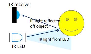
Fig 5.1 functional diagram
In hypothetical this IR sensor separate ranges up to 30cm and working voltage is 5V. This module comprises of an IR Transmitter, recipient, a LED, supply for the module ie, VCC and Ground stick appeared in Fig.
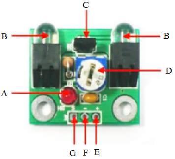
Fig. 5.2 IR Sensor
- Signal indicator LED
- IR transmitter
- IR Sensor
- Preset
- VCC(+) [operating range: +4V to +6V]
- GND
- Output signal (s)
5.2 The features of the device include:
- 5V fueled, low current utilization, under 10mA.
- 3 stick interface in particular Signal, GND and 5V.
- Small LED as marker for identification status.
- Obstacle recognition up to 8cm.
- Adjustable detecting range (2cm – 8cm)
- Single piece yield.
- Compatible with a wide range of microcontroller
Chapter 6: Relay
A relay is an electrically operated switch. Many relay use an electromagnet to operate a switching mechanism mechanically, but other operating principle are also used relays are used where it is necessary to control a circuit by a low-power signal (with complete electrical isolation between control and controlled and circuit), or where several circuits must be controlled by on signal.
The relay’s switch connections are usually labeled COM, NC and NO:
- NO = Normally Open, (COM is connected to this when the relay coil is on).
- NC = Normally Closed, (COM is connected to this when the relay coil is off).
- COM = Common, (always connect to this; it is the moving part of the switch.)
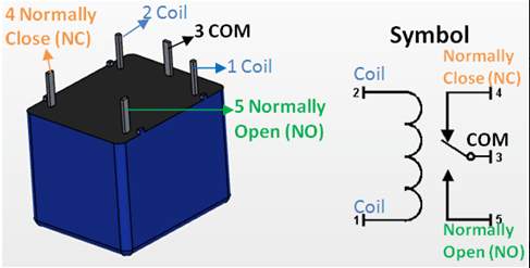
Fig 6.1 relay
Connect to COM and NO if you want the switched circuit to be on when the relay coil is on.
Connect to COM and NC if you want the switched circuit to be on when the relay coil is off.
Advantages of relays:
- Transfers can switch AC and DC, transistors can just switch DC.
- Relays can switch high voltages, transistors can’t.
- Relays are a superior decision for exchanging substantial streams (> 5A).
- Relays can switch numerous contacts without a moment’s delay
Disadvantages of relays:
- Relays are bulkier than transistors for switching small currents.
- Relays can’t switch quickly (with the exception of reed transfers), transistors can switch ordinarily per second.
- Relays utilize more power because of the present moving through their loop.
- Relays require more present than numerous chips can give, so a low power transistor might be expected to switch the current for the transfer’s loop.
Chapter 7: Solenoid Valve
7.1 Working Principle
A solenoid valve is an electromechanical gadget utilized for controlling fluid or gas stream. The solenoid valve is controlled by electrical current, which is go through a loop. At the point when the curl is empowered, an attractive field is made, making a plunger inside the loop move. Contingent upon the outline of the valve, the plunger will either open or close the valve. At the point when electrical current is expelled from the curl, the valve will come back to its de-empowered state.
The adjoining outline demonstrates the essential parts of a solenoid. The mechanical power created by the solenoid is utilized to pack the spring which thusly is utilized to restore the center to the solenoid’s un-invigorated state. A similar impact can be accomplished by turning around the extremity of the current connected to the solenoid. This has the impact of switching the shafts of the attractive lines of power and thusly turning around the bearing of mechanical power put upon the center.
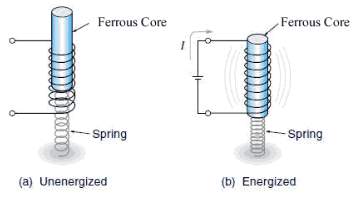
Fig. 7.1 Functional diagram of Solenoid valve
In direct-acting solenoid valves, the plunger directly opens and closes an orifice inside the valve. In pilot-worked valves (likewise called the servo-type), the plunger opens and shuts a pilot hole. The bay line weight, which is driven through the pilot hole, opens and shuts the valve seal.
The most well-known solenoid valve has two ports: a bay port and an outlet port. Propelled configuration may have at least three ports. A few outlines use a complex kind plan.
Solenoid valves make automation of fluid and gas control possible. Modern solenoid valves offer fast operation, high reliability, long service life, and compact design.
7.2 Different parts of a solenoid valve
The illustration below depicts the basic components of a solenoid valve. The valve shown in the picture is a normally-closed, direct-acting valve. This type of solenoid valve has the most simple and easy to understand principle of operation.
- Valve Body
- Inlet port
- Outlet port
- Coil/solenoid
- Coil windings
- Lead wire
- Plunger
- Spring
- orifice
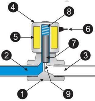
Fig. 7.2 solenoid valve
The media controlled by the solenoid valve enters the valve through the inlet (Part 2 in the delineation above). The media must course through the orifice (9) preceding proceeding into the outlet port (3). The orifice is shut and opened by the plunger (7).
The valve presented above is an ordinarily shut solenoid valve. Typically shut valves use a spring (8) which presses the plunger tip against the opening of the orifice. The fixing material at the tip of the plunger shields the media from entering the orifice, until the plunger is lifted up by an electromagnetic field created by the coil.
- Valve body: This is the body of the valve to which the solenoid valve is associated. The valve is typically associated in the process stream pipeline to control the stream of certain liquid like fluid or air. Normally the spill out of the valve is controlled by the handle, yet if there should be an occurrence of the programmed valve the solenoid valve is associated with the valve.
- Inlet port of the valve: This is the port through which the liquid enters inside the programmed valve and from here it can go into the last procedure.
- Outlet port: The liquid that is permitted to go through the programmed valve leaves the valve through the outlet port. The solenoid valve controls the stream of the liquid from channel port to the outlet port. The outlet port is in the end associated with the procedure where the liquid is required.
- Coil/Solenoid: This is body of the solenoid curl. The body of the solenoid curl is round and hollow fit as a fiddle, and it is empty from inside. The body is secured with steel covering and it has metallic wrap up. Inside the solenoid valve there is solenoid loop.
- Coil windings: The solenoid comprises of a few turns of the enameled wire twisted around the ferromagnetic material like steel or iron. The curl frames the state of the empty chamber. Remotely this curl is secured with the steel covering and inside the empty part there is a plunger or the cylinder, whose movement inside the empty space is controlled by the spring.
- Lead wires: These are outer associations of the solenoid valve that are associated with the electrical supply. The current is provided to the solenoid valve from these wires. At the point when the solenoid valve is empowered, the present courses through these wires to the solenoid valve and when the solenoid valve is de-stimulated the stream of current stops.
- Plunger or cylinder: This is the strong round metallic part barrel shaped fit as a fiddle and put in the empty segment the solenoid valve. At the point when the electrical current is gone through the solenoid valve, the attractive field is produced inside the empty space. Because of this the plunger tends to move vertically in the empty space. At the point when the electrical current is halted to the solenoid valve, the attractive field is ceased and the plunger is remains the current place because of the power of the spring.
- Spring: The plunger moves inside the empty space because of the activity of the attractive field against the activity of the spring For one, the plunger is in the vertical position, so the spring helps keeping it at the coveted position as opposed to enabling the plunger to tumble to the base because of gravity when the current to the solenoid valve is ceased. Besides, the spring likewise keeps the development of the plunger because of power of the liquid coursing through the valve body. On the off chance that the spring was not there the plunger would have climbed when the liquid is available and moved down when the liquid isn’t there. In this way the spring really powers the plunger to do the control of the liquid. It permits the development of the plunger just to the degree when the electric current is coursing through the solenoid valve.
- Orifice: The opening is an imperative piece of the valve however which the liquid is streaming. It is the association between the channel and the outlet port. The stream of liquid from the delta port to the outlet port happens from this port. In the normal valves, this port is secured with the valve plate at the base of the stem of the valve to which the handle is associated. Subsequently in standard valves, the opening of the orifice are controlled by the handle, however if there should be an occurrence of the solenoid valves, the opening of the orifice is controlled by the plunger. The development of the plunger is thus controlled by the spring and the present moving through the solenoid valve.
If the current passing through the solenoid valve is constant, the position of the plunger and hence opening of the orifice remains constant. If the sensor senses that more flow of the fluid is required, it allows the increase in current passing through the solenoid valve, which creates more magnetic field and more upwards motion of the plunger. This prompts additionally opening of the orifice and more stream of the liquid from the delta port to the outlet. In the event that the required stream of liquid is less, the sensor enables entry of the lesser current to the solenoid valve. At the point when the sensor detects that the liquid is not any more required all the while, it stops the stream of the current to the solenoid valve totally.
Chapter 8: Conveyor belt
A conveyor belt is the carrying medium of a belt conveyor system (often shortened to belt conveyor).A belt transport framework is one of numerous sorts of transport frameworks. A belt transport framework comprises of at least two pulleys (in some cases alluded to as drums), with a perpetual circle of conveying medium—the transport line—that pivots about them. Either of the pulleys are fueled, moving the belt and the material on the belt forward. The fueled pulley is known as the drive pulley while the unpowered pulley is known as the idler pulley. There are two fundamental mechanical classes of belt transports; Those all in all material taking care of, for example, those moving boxes along inside a production line and mass material dealing with, for example, those used to transport huge volumes of assets and agrarian materials, for example, grain, salt, coal, mineral, sand, overburden and that’s only the tip of the iceberg. Today there are diverse sorts of transport lines that have been made for passing on various types of material accessible in PVC and elastic materials.
8.1 Principle of conveyor belt
The main principle applied to all variants of conveyor belts is fairly simple. Friction transports materials down a conveyor belt. Grating transports materials down a transport line. A wide portion of material, be it cowhide, elastic or engineered material, extends and circles between two pulleys/rotors. Engines control the pulleys, turning them both either clockwise or anticlockwise. As the pulleys turn, grinding happens between the pulley and the belt of material, impelling the belt to move around the circle. The two pulleys must turn a similar way, else the belt won’t move.
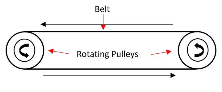
Fig 8.1 Conveyor Belt
Like the greater part of present day life’s mechanical miracles, the real working rule of transport lines is generally basic. This permits the transport line to be fluctuated and arranged to suit a wide range of utilizations. In some transport lines just a single of the pulleys is controlled by an engine, making it the drive pulley which thus pivots the other curve pulley. While transporting substantial materials (i.e. metals), a progression of rollers set in the middle of the two pulleys prevent the transport lines from drooping amid transport.
8.2 Benefits of conveyor belt
- They can be utilized to transport an extensive variety of materials.
- Transport lines can be intended to move little or vast, coarse and fine things. For instance, they can be utilized as a part of a refreshment organization to move 300ml containers of drink and in mining destinations to transport huge amounts of metal.
- They can be utilized for multi directional development
- Transport lines can be slanted on a level plane or vertically. In either case, they are intended to guarantee that the material being transported does not tumble off.
- They require less energy to work in contrast with different sorts.
- The material is continually on the move, thereby requiring negligible vitality.
- They can be custom-worked to fill particular needs.
Chapter 9: References
http://www.tkkcorporation.com/mitsubishi/fx3g.htm
BOOKS: Programmable logic controllers (PLC) by JOHN W.WEBB
Cite This Work
To export a reference to this article please select a referencing stye below:
Related Services
View all


Related Content
All TagsContent relating to: "Supply Chain"
A Supply Chain is a system in place between companies and their suppliers, from producing a product to distributing it ready to be sold. An effective and smooth running supply chain can contribute to the successful running of a business.
Related Articles
DMCA / Removal Request
If you are the original writer of this dissertation and no longer wish to have your work published on the UKDiss.com website then please: