Guidelines for the Dynamic Behaviour of the Prestressed Concrete Floor Systems
Info: 7234 words (29 pages) Dissertation
Published: 10th Dec 2019
Tagged: Engineering
Chapter 1
1 Introduction
1.1 Problem definition
As of today, the floor vibration due to normal occupant-induced loads has become a common concern in prestressed concrete systems. In buildings, floors are the structural components that occupants primarily contact. In design issue, the vibration induced due to occupant’s activities such as walking, running and jumping is of major concern, especially in the long-span floors. In modern prestressed structural floor systems, the vibrations due to the occupants are of major concern because of the use of high-strength lightweight materials and prestressing allows relatively light and long spans. The vibrations in the floor systems should be limited to certain factors to achieve Human Comfort Level.
To achieve this goal many researchers have been working with regards to the study of vibrations in prestressed floor systems. Various experiments are being done to get a better understanding of its behaviour and content.
In this thesis, the dynamic behaviour of the isolated beam and continuous beam is analysed and the discussion includes:
To predict the fundamental natural frequency in an isolated and continuous prestressed concrete beam due to free vibration.
- Slab and beams interaction studies are carried out in free vibration.
To study about the mode shapes in the prestressed concrete beam systems.
- To determine the active mode in the system, research is carried out by comparing the length of the girder and distance between beams.
All the above-mentioned topics are the main goals to be achieved in this thesis. Although researchers from the past have covered some of the parts of the subject in the field of floor vibration, this is an extension of the past studies and the knowledge gaps in the past will be found.
Previous research in the field of vibration analysis in prestressed beams and floor systems as follows:
Da silva et al. attempted to grow hypothetical and exploratory analysis of dynamic behaviour caused by human activities. The vibration characteristics determined are of slab component, given primary importance to the floor vibration. Whereas the vibrations in the beams was neglected.[1]
Ljunggren and Agren [2] did some uncommon tests to make an artificial mass damper and decide the measure of viscous-elastic materials which ought to be added to the floor framework to relieve vibration. They used finite element method to know the measure of viscous-elastic materials and contrasted their new damping outcomes with the actual floor system so they could perceive the part of changing over damper components in between the test.
Sapountazkis [3] analysed the dynamic behaviour of a reinforced concrete slab stiffened by steel bars. But the analysis made was only on an isolated beam and the behaviour of the continuous beam was overlooked.
Ebrahimpour and Sack [4] described methods to mitigate floor vibration due to human activities. They explained two techniques using advanced materials namely, semi-active control and passive control.
By this study, an attempt is made to find some limited answers to cover the gaps in the study. In this manner, keeping in mind the end goal to make this research clear, some fundamental question with regards to the primary speculations will be discussed in the following chapters.
1.2 Objectives
The main goal of this research is to suggest realistic guidelines for the dynamic behaviour of the prestressed concrete floor systems using numerical techniques. The key objectives of this project are as follows:
- To study the dynamic behaviour of isolated prestressed concrete beam with various girder lengths.
- To study the dynamic behaviour of continuous prestressed concrete beams with different beam section properties.
- Computation of different modes of the structure in free vibration analysis.
- To validate the numerical results.
- Active mode of the system is identified through different cross-sectional and physical conditions in prestressed concrete beams and floor systems.
1.3 The scope of this study
This study will be in five chapters as follows:
- Chapter one: This chapter is about the introduction and problem definition.
- Chapter two: This section is a hypothetical examination of some of the past researchers in the field of prestressed concrete beams and floor systems. Thereafter the key targets from late reviews will be examined to decide their essential gaps. In like manner, some methodologies as a requirement for research will be discussed using finite element approach.
- Chapter three: Before beginning our numerical analysis, an outline of essential and basic ideas about numerical systems is introduced as a part of this thesis. The modelling procedure and the accessible strategies to take care of current finite element issue under free vibration analysis will be discussed.
- Chapter four: This chapter is about the discussions of results obtained using numerical methods.
- Chapter five: Conclusions of this research and recommendations for future study.
Chapter 2
2 Literature Review
2.1 Introduction
In this chapter basics of vibrations in structures are introduced and the previous work of the researchers in the field of vibration are briefly described.
This chapter deals with the following:
- Introduction to prestressed systems
- vibration analysis
- Review on Human induced vibration
- Review on Human perception of vibration
- Vibration in prestressed concrete beams and floor systems.
- Discussion on factors affecting the nature of vibration.
2.2 Prestressed Beams and Floor Systems
2.2.1 Introduction
Since the end of 19th century reinforced concrete is widely used in the structures. As the concrete has very low tensile strength, concrete is prestressed. Prestressing concrete allows long-span floor system with column-free infrastructure. Modern infrastructure is looking for long-span floor system with more open spaces. Prestressing concrete allows long span floors while reducing the height of the slab. The main reason for using prestressed concrete structures is to reduce the cracking in concrete by increasing the tensile strength of the concrete. Moreover, in economical point of view prestressed concrete gains advantage over reinforced concrete. This chapter deals with the basic prestressing concepts related to prestressed beams and floor systems.
2.2.2 Principle of Prestressing
Prestressing concrete induces compressive load in the concrete and this compressive force reduces or eliminates the tensile forces in the concrete. Due to this cracking is reduced or eliminated in concrete and as a result, the stiffness is increased. Prestressing also develops internal forces which oppose the external load thereby deflections are reduced or eliminated.
The prestressing force can be applied with an eccentricity, which increases the compressive stress in the concrete leading to more external load carrying capacity. The load carrying capacity varies with the eccentricity of the prestressing force and so for best results usually draped tendons are used. Draped tendons apart from imposing the compressive force in the concrete, it also results in transverse force wherever the direction of the tendons changes.
2.2.3 Methods of prestressing
Prestressing deals with tensioning the high strength steel using hydraulic jacks. The tensioning process can be done before or after the concrete is cast. Based on this prestressed concrete is classified into
- Pre-tensioned concrete
In this method, the tendons are first tensioned and the concrete is cast. The prestressing force is developed due to the bond between the steel and concrete.
- Post-tensioned concrete
In this method, the concrete is the first cast on the hollow ducts later when the concrete attains its full strength the steel tendons are tensioned and space is filled with grouting material. The prestressing force is developed due to grouting.
Most in-situ prestressed concrete is post-tensioned concrete. As it is corrosive resistive and the prestressed losses are relatively small.
2.2.4 Prestressed losses
The prestressing force in the tendons that are subjected to tension eventually decrease over time throughout the life of the structure. These losses can occur immediately after prestressing and over the life of the prestressed member. The losses can occur due to elastic strain in the concrete, anchor wedge draw in, friction losses and due to long term effects of creep and shrinkage strain. AS3600 recommends that the final prestress force in the tendons shouldn’t be less than half of the tendons characteristic minimum breaking strength fpb.
2.3 Vibration analysis
According to Clough and Penzien [5], the basic equation to analysis the dynamic behaviour of any motion can be obtained from Newton’s second law. Consider a system of mass m, if this system is excited with a force f(t) and displaced through a distance of ut , then the equation of motion is:
dmdudtdt=f(t)
Finite element method divides any structure into several finite parts. The equation of motions can be developed to all the divided elements at their nodal points. To understand the dynamic behaviour of the structure some parameters such as stiffness, flexibility, mass and damping are introduced briefly in the following sections.
2.3.1 Stiffness in structures:
The stiffness of a structure is defined as actions (forces or moments) required to unit values of corresponding displacements (translational or rotational). Flexibility is the displacement corresponding to unit values of actions. Stiffness is the inverse of flexibility.
For example:
The stiffness of a simply supported beam is:
k=384EI5l3=1∂
2.3.2 Effects of prestressing on geometric stiffness
According to Eriksson [6] says that prestressing as the compressive axial load and it reduces natural frequencies. This phenomenon is due to the second-order effects which lead to a reduction in structural stiffness and causes buckling.
Clough and Penzien [5] mentioned that the compressive axial force in the system reduces the stiffness
Kby geometric stiffness
[K]G. Following equation represents the effective stiffness
[K]Eafter prestressing.
[K]E=K-[K]G
Khan and Williams [7] suggest that the above phenomenon is not due to the axial forces caused by internal prestressing. The tendon profile will be like a deformed prestressed member and as a result, there is no additional eccentricity formed between the centroid of the member and the tendon. Therefore, second order effects caused due to prestressing should not be considered while analysing the dynamic characteristics of internally prestressed concrete floor systems.
2.3.3 Modal analysis:
Modal analysis is used to calculate the values of natural frequencies and mode shapes of nodes and the structure. A structure naturally tends to vibrate at its natural frequency without any application of excitation force. The mode shape shows the deflected shapes of the structure at respective natural frequencies.
The equation of motion can be expressed in terms of natural frequencies for respective mode shapes.
E(n)v̂n=0
Where
E(n)=k-ωn2m
K is the stiffness matrix, ωn is the natural frequency and m is the stiffness matrix.
2.3.4 Theoretical modal analysis
If the structure is undamped and if there is no excitation force then the equation of motion is as follows:
MẌt+Kt={o}
To obtain the natural frequencies of the structure calculate the stiffness matrix and mass matrix and substitute it in the following equation.
detK-ω2M=0
From the modal analysis, the eigen vector can be calculated. They can be scaled in two ways unity normalisation and mass normalisation.
2.3.5 Vibration
Vibration is an instant of vibrating of an elastic body. Floor system can vibrate from its original position when a force is acted on it. Floor vibration can be categorised into free and forced vibration. Free vibration takes place when the force is applied on a floor system the system vibrates in its natural frequency if no excitation force is exerted. Forced vibration is due to continuous excitation of the floor system.
2.3.6 Dynamic loading
Dynamic loading changes over time depending on the excitation force. Walking induces a transient type of loads. Rhythmic activities such as dancing induce periodic loads. Impacts cause impulsive loads due to activities like a single jump.
2.3.7 Mode Shape
The motion of the structure is defined by its mode shape. These mode shapes are considered because in multi-degree of freedom (MDOF) the structure oscillates in different patterns. At these mode shapes, the structure oscillates in the form of the simple harmonic motion such as sine graph.
2.3.8 Free vibration equation
The equation of motion for a damped structure vibrating without any excitation force is as follows:
mẍ+cẋ+kx=0
Where x is displacement, m is mass, c is damping constant, k is the stiffness.
This is formed based on the equilibrium of forces:
mẍ– Internal force due to inertia
cẋ– Damping force like viscous force
kx– Elastic force caused due to spring action of the structural element
If the damping is ignored the equation can be expressed as:
mẍ+kx=0
For an MDOF the solution of the equation can be expressed as a simple harmonic motion as follows:
Xt=asin(ωt+θ)
Where ‘a’ indicates the function shape which is independent of time and
θis phase angle. The acceleration of the free vibration can be obtained by double derivating the displacement
Xtequation and is as follows:
ẍ=ω2asinωt+θ=-aω2
By substituting the displacement and acceleration in the equation of motion, we get:
k-ω2ma=0
The above equation is the eigenvalue equation.
Where
ω2is the eigenvalue and
ais the displacement vectors which indicates the mode shape or Eigenvector.
2.3.9 RMS acceleration
RMS acceleration refers to Root Mean Square acceleration. It is the average of all the responses of vibration. The equation of RMS acceleration is as follows:
a=(1T∫0Tatdt)12
Where T – Time in seconds.
2.4 Historical review
In vibration point of view, floors are normally classified as low-frequency floors and high-frequency floors. Floor system in heavy construction are generally low-frequency floors, in these type of floors, a resonance vibrations can be sensed by a person. Floors system in light constructions are generally high-frequency floors and a person staying still can sense the vibrations due to another person activities. In this research vibrations in high-frequency floors is consider as prestressed concrete constructions are light in weight.
The first study was done by Reiher and Meister in 1930. They had carried out their experimental work by considering 10 specimens under continuous steady-state vibration. By comparing the critical frequency and maximum displacement they had attempted to present human tolerance in steady state vibration. Their interest is mainly on the receivers (humandma behaviour.
Lenzen [8] developed a procedure to check the floor vibrations. This procedure is used to check the floor vibrations during the design phase. Goldman [9] proposed a criterion on human perception. He had considered peak accelerations and frequency of vibration to suggest three-floor acceptability criteria from a variety of sources.
- Threshold of perception
- Unpleasant
- Intolerable
Murray [10] considered the human perception criteria as acceptable or annoying. Serviceability of floor vibration is classified as springiness by Ohlsson [11]. He said that the vibration can be observed by the person creating vibration. Pavic and Reynolds [12] said that the footfall induced vibration can be observed by a different person apart from the person making it vibrate.
Ellingwood and Tallin [13] conducted vibration tests on a shopping centre and suggested design criteria for composite steel-concrete beam and floor systems based on maximum deflection caused by a point load anywhere in the whole system.
Toratti [14] has proposed vibration and acceptance limits classes for various type of floor systems. They conclude that for lightweight structures point load deflection is also the best indicator to analyse floor vibration apart from the natural frequency and maximum velocity. They had considered only the fundamental frequency and whole point load deflection and the rest of the vibration criteria such as displacements, velocities and accelerations are not considered.
2.5 Sources of vibrations:
There are several sources to induce a vibration in a structure. They can be classified as external and internal sources. Vibration in a structure which is caused by sources which are outside the building is called as external sources. Vibrations induced due to any source inside the building is called as internal sources. As a part of this research, vibration induced by internal sources especially human-induced vibrations are discussed.
The force due to human activities can be harmonic or periodic or transient or impulsive or a combination of these.
According to ISO 1989 [15], vibrations due to human activities are sub-divided into two categories:
Transient vibrations:
This type of vibrations is due to impulsive force and after some time the acceleration of vibration will come down to zero. For example, vibration caused due to jumping.
Continuous vibrations:
These are the vibrations which are continuous in nature, separated by lower wavelengths like a sine curve. For example, vibration caused by a group of people walking.
Human activities in a structure are never the same and so the vibrations in the structure.
2.5.1 Various dynamic forces due to human activity
Murray et al. [16] based on the Fourier sum, proposed an equation for human walking. The equation is represented in terms of load and time.
Pt=P01+∑n=1nαnsin2nπfpt-ϕn
Where
P0– static force due to a person,
αn– nth harmonic Fourier coefficient,
fp– activity frequency,
t– time in seconds,
ϕn– phase angle of respective nth harmonic with first harmonic. But this equation can be used to calculated the dynamic forces of the first four harmonics of pace frequency. Ellingwood and Tallin [13] proposed that the major contribution is due to the first, second and third harmonics. The rest of the harmonics contribution will be less than 10%. For an individual walking between 1-3 Hz, there are several ideas proposed by the researches relating to the Fourier coefficient αn. Whereas for the first four harmonics Murray et al. [16] assumed that the values range between 0.05 – 0.33 and Ellis [17] considered between 0.08 and 0.46. From the following Fourier coefficient figure walking excitation, rhythmic load can be calculated.
Ellingwood and Tallin [13] discussed the variation in forces when a group of people walking. Impact type of loading from single heel drops is described by Ohlsson [11], considering the average weight of crowd as 86 kg. The following figure shows loading variation up to 50 ms.
Ellingwood and Tallin [13] obtained the relation between the dynamic forces frequency and number of steps per minute due to walking and said that if a person is walking normally with a rate of 112 steps per minute then the forcing frequency will be around 1.86 Hz.
For the harmonic type of loading Allen [18] proposed an equation to calculate the exerted dynamic force (F).
F=p[1+∑aicos2πift]
Where
pis the average person’s weight (normally 72 kg),
aiis dynamic load factor,
fis frequency of vibration.
As per SCI P354 [19] forcing function is periodic due to the walking type of activity. The following figure shows the dynamic load function due to continuous walking.
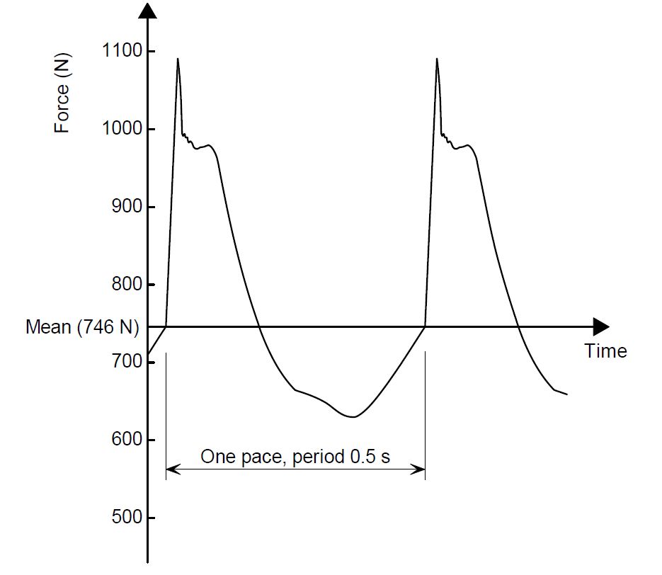
Figure 2.1 Dynamic load function for continuous excitation due to walking [19]
The amplitude of the force in the above figure can be calculated by Fourier analysis. The amplitude of nth harmonic is as follows:
Fh=αhQ
Where
αhis the hth harmonic Fourier coefficient,
Qis the static force applied by a normal person (usually taken as 76*g, g = 9.81 m/s2).
Young [20] proposed an equation for the impulsive type of excitation due to walking. This equation is developed from Young’s theoretical model.
F=60fp1.43fn1.3Q700
Where Fp is pace frequency, fn is the frequency of considered mode, Q is a static force applied by a normal person (76 kg * 9.81 m/s2).
2.6 Human perception of vibration
Human perception of vibration depends on various factors such as intensity of vibration, the direction of the vibration, amplitude of the wave and damping in the structure. Human perception studies in vibration analysis was first done by Reiher and Meister in 1930. They developed a scale to assess the human tolerance based on maximum deflection and frequency of vibration under steady state human vibration. Later, Lenzen [8] modified Reiher-Meister scale for vibrations caused by walking impact. Lenzen [8] also said that the original scale can be used for floors with critical damping less than 5% provided the displacement multiplied by a factor 10.
Wiss and Parmelee [21] experimental study suggests that the product of displacement and frequency is constant for a combination of human exposure to vibration and damping in the structure. They experimented on a group of people by considering frequency, displacement and damping. They suggested a vibration criteria scale.
Allen and Rainer [18] came up with a vibration criterion by considering the acceleration and floor damping. They performed heel impact test on long-span floors to analyse the vibrations in the floor systems. Their line criterion is particularly intended to residential buildings and offices. If the damping in the structure increases the continuous steady state vibration becomes transient vibration which leading to small vibration patterns.
Murray [10] performed heel drop tests on different types of floors under different conditions and he proposed a vibration scale based on the results. The suggested human perception scale is based on displacement, frequency and damping. The parameters in his scale are same as Wiss-Parmelee scale.
International Standards Organisation [15] [15] considered root mean square (RMS) acceleration and frequency and proposed a vibration criteria. These vibration limits are based on a baseline curve. For a different type of occupancies, different multipliers ranging from 1 to 128 are used to baseline curve.
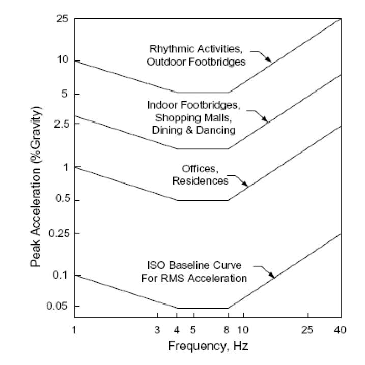
Figure 2.2 Peak accelerations for human comfort for vibrations due to human [15]
Toratti [14] had carried out several experiments based on vibration on floors. They had carried out experiments for 10 years on lightweight floor systems with a fundamental frequency greater than 10 Hz and proposed vibration classes for residential and office buildings.
2.7 Effects of vibration to structural elements in prestressed concrete beam and floor systems:
Prestressed concrete floors are usually constructed as band beam and slab or flat slab. In prestressed floor system, there is no supporting beam to the floor system and the band beam acts together with the floor system.
2.7.1 Beam response
The vibrational characteristics of the beam system are analysed by most of the researchers, considering it vibrate about columns as a simply supported beams. But in the real condition the interaction between the column and the beam will be between simply supported and fully fixed. The natural frequency of the system is directly impacted by the stiffness at the interface of beam and column.
2.7.2 Floor response
Dynamic behaviour of prestressed concrete floor systems have several numbers of modes, but only some modes are considered in this discussion. In prestressed concrete floor systems, the shape of the basic mode can be created by maximum deflection due to distributed or concentrated live load. To avoid resonance phenomenon assessment of the fundamental natural frequency is set as primary criteria to design floor serviceability.
The resonance phenomenon was discussed in 1978 by Weaver and Johnston for any structural system. They also mentioned that the structure will vibrate if a harmonic load of force Po and frequency f is applied. Here they introduced a parameter D, which is the ratio of resultant amplitude to static displacement and can be calculated as follows:
D=1(1-β2)2+(2βξ)2
Where
ξ – damping ratio
β – ratio of applied load frequency to fundamental frequency
Note that the applied load frequency should be close to the fundamental frequency and the structure should be damped lightly. When β =1 peak steady state response can be observed. This is the primary cause to study the active fundamental frequency of the system. To improve the damping artificial damper, viscose elastic material, or tuned mass damper (TMD) can be used.
In 1994, the vibration serviceability criteria of post-tensioned floors were addressed by UK Concrete Society in Concrete Society Technical Report 43 (CSTR43). This handbook provides the procedure to check the vibration serviceability of post-tensioned concrete floors.
Pavic et al. [22] has modelled the dynamic performance of post-tensioned concrete floors using finite element analysis. He proposed a procedure to check the vibration serviceability criteria for post-tensioned concrete floors using finite element analysis and this seems to be satisfactory than CSTR43 criteria. He recommended the appropriate boundary conditions, stiffness, mass and damping factors for post-tensioned floors.
Some guidelines to human-induced floor vibration are mentioned in Australian standard domestic metal forming and AS 2670 codes. The serviceability design in this code mainly concentrates on floors which have natural frequency more than 8 Hz. [23]
SCI guidelines was published by Wyatt [24] to evaluate human induced floor response. In his view, he considered the root mean square acceleration as the main criterion.
arms=apeak2
Note
arms ≤0.005R if 3 Hz≤ fo ≤8 Hz
arms ≤0.005Rfo8 if fo>8 Hz
Where R – rating value of response
Wiss and Parmelee [21] proposed the following equation
R=5.08×(f1A1ξ0.217)0.265
Where R – rating value of response,
f1– lowest floor natural frequency,
A1– maximum amplitude and ξ – damping ratio.
“Response factor” was introduced by Willford et al. [25]. It is the ratio of vibration level to the threshold of human perception and the threshold baseline curves are mentioned in BS6472. Following table indicates the typical criteria for footfall induced vibration.
| Type of building | R |
| Normal office | 8 |
| Busy office | 12 |
| Special office | 4 |
| Operating theatre | 1 |
| Hospital residential | Night time – 1.4
Day time – 2-4 |
Table 2.1 Typical criteria for footfall-induced vibration [25]
2.8 Natural frequency in the system
To determine the intensity of the dynamic response, fundamental frequency plays an important role apart from characteristics of loading. Natural frequency
ωof a system or member depends on the stiffness
kand mass
mof the system. It can be calculated by using the following equation.
ω=km
A floor having high stiffness and low mass will have a high natural frequency. The fundamental can be classified in horizontal and vertical direction. It can also be termed as horizontal and vertical modes. Institute of Structural Engineers mentions that vertical mode has a sufficiently greater component to displaces the system in the vertical direction due to vertical dynamic excitation. Whereas the horizontal dynamic mode excites a horizontal mode which can vibrate the system in lateral or longitudinal directions. In the real structure, a combination of these two modes is seen. But here the vertical mode is taken as the fundamental mode of the system.
2.8.1 Calculation of natural frequency in prestressed concrete beam systems
The frequency of free elastic vibration of a uniform beam section can be obtained by the equation proposed by Hicks [26].
fn= kn2πEImL4
Where
EI– dynamic flexural rigidity in Nm2
m– effective mass in kg/m
L– member span in m
kn– constant for nth mode of vibration, depends on the boundary support conditions and can be determined from the following table
| Boundary condition | Kn |
| Simply supported | π2 |
| Fixed/Pinned | 15.4 |
| Fixed both ends | 22.4 |
| Cantilever | 3.52 |
Table 2.2 Kn for different boundary conditions [26]
For a simply supported beam with uniform loading for which K1 is π2, the fundamental f1 (lowest) natural frequency of the beam is as follows:
f1=17.8δ≈18δ
Where δ – maximum displacement
Dunkerly’s approximation states that from the above equation the fundamental natural frequency can be obtained when the δ is considered as the sum of all deflections of the structural components (Primary beams, Secondary beams and the slab).
Wyatt [24] estimated the natural frequency by calculating the global self-weight deflection in the system.
2.9 Effect of vibration on non-structural elements
Energy dissipation and damping affect the vibration of the structure in the prestressed concrete beams and floor systems. These factors also influence on the fundamental frequency and the damping ratio of the system. The following table shows the damping measure in different systems which were suggested by Bachmann and Amman [27].
| System of the structure | Damping measure ξ |
| Reinforced concrete structures | 0.7% |
| Composite floor system | 0.5% |
| Timber structure | 1.5% |
| Steel structure | 0.3% |
Table 2.3 The measure of the damping in different system [27]
As already introduced, Lenzen [8] experimental analysis states that masses in the structure increases the damping. He found that four occupants increase damping over 300 percent.
In real structures damping nature usually, lie between viscous and frictional. If the damping forces are viscous then they are proportional to the magnitude of velocity in opposite direction. If the damping forces are constant and restrict the motion of the body it is known as frictional or coulomb damping and they are independent of frequency and amplitude. In prestressed concrete, both frictional and viscous damping influence the floor vibration.
2.10 Review of recent researches
Hicks [26] had tried to measure floor response on 18 different floors and then compared the results obtained with the numerical analysis. He has performed the experimental analysis based on heel drop excitation, instrumental hammer excitation and impact test. The experimental results and the numerical analysis were quite comparable and many other researchers have done a similar type of analysis.
Sapountazkis [3] performed numerical analysis on the dynamic issue of reinforced concrete slab which is stiffened by steel beams. The analysis performed and the results extracted were limited to an isolated beam criteria. The analysis of the continuous beam is yet to be performed.
Toyota [28] carried out an experimental study on vibration characteristics of the prestressed concrete beam based on the effect of prestressing force. The size of the model beam used in the test is L9,000mm, W400mm, H600mm and a PC rod of diameter 32mm was used. The compressive strength of concrete is 36 N/mm2.The following figure shows the modelled prestressed beam.
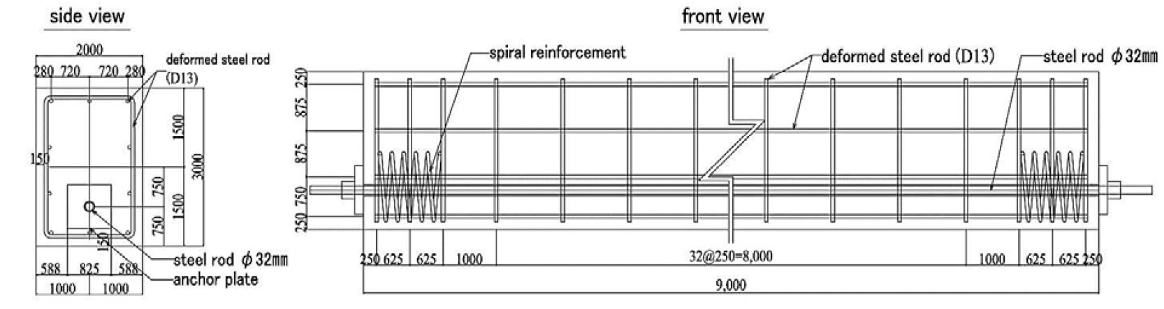
Figure 2.3 Model beam [28]
In the test, the effect of prestressing force on vibration characteristics before and after grouting was also done. The prestressing force applied on the rod was 490 (kN) and it is the design prestress force which is at 100%. The vibration test was performed by decreasing the prestress force over 10% starting from the design prestress force to 0%. To measure the vibrations in the beam accelerometer, laser displacement sensor and strain gage were installed. The natural frequency of the system was estimated using the sweep test. The beam was tested by applying forced vibration at first mode. Toyota [28] also performed numerical analysis on the same beam model and the results of the experimental and theoretical analysis were close enough to compare. He concludes that if the prestress is lowered the natural frequency of the beam is also lowered, but on the other hand the damping in the beam increases.
However, the vibration characteristics in the actual bridge were different because the vibration are induced by multiple types of vehicles and in this experiment, he has assumed it as the vibrations are in various patterns. Furthermore, the boundary conditions considered were based on an isolated beam but in the real structure it is different.
2.11 Need for research
After reviewing the previous literature about the dynamic characteristics of the prestressed concrete beam and floor systems, significant gaps have been found in the study. According to researcher’s fundamental frequency in floor system is due to floor or slab response but the primary element in serviceability design is a slab.
Whereas others believed that the fundamental frequency can be determined from the combination of modes. According to Dunkerly’s equation.
1f12=1fs2+1fb2+1fp2
Where
fs is slab component
fb is secondary beam component
fp is primary beam component.
They believe that to get the natural frequency of the system all modes should be combined. But the fundamental frequency can be obtained by the active mode in the system rather than combining all modes in a prestressed concrete beam and floor system. Furthermore, to get sound and valid dynamic analysis results real circumstances should be considered. All these subjects mentioned before are the main ways to finish previous studies.
2.12 Research methodology
In this thesis, the theoretical and analytical analysis is done to meet the objectives of this research. The theoretical analysis is based on the dynamic behaviour of the prestressed concrete floors under free vibrations and the analysis is made using finite element software ABAQUS and RAPT. Then results of the theoretical analysis are verified by experimental or analytical analysis using finite element method and the analytical calculations are done using EXCEL or MATHCAD.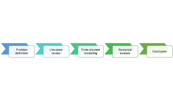
Figure 2.4 Research Methodology
2.13 Expected Outcomes
The dynamic analysis on the prestressed systems is done as a part of serviceability. In serviceability, the natural frequency of an isolated and continuous beam is calculated. The natural frequency of the system is calculated by analysing the mode shapes and by identifying the active mode in the system.
References
1. da Silva, J.G.S., et al., An evaluation of the dynamical performance of composite slabs. Computers & Structures, 2003. 81(18–19): p. 1905-1913.
2. Ljunggren, F. and A. Ågren, Development of a new damper to reduce resonant vibrations in lightweight steel joist floors. Applied Acoustics, 2002. 63(11): p. 1267-1280.
3. Sapountzakis, E.J., Dynamic analysis of composite steel–concrete structures with deformable connection. Computers & Structures, 2004. 82(9–10): p. 717-729.
4. Ebrahimpour, A. and R.L. Sack, A review of vibration serviceability criteria for floor structures. Computers & Structures, 2005. 83(28–30): p. 2488-2494.
5. Clough, R.W. and J. Penzien, Dynamics of structures. 1993. Copyright of Applied Mechanics & Materials, 1993.
6. Eriksson, P.-E., Vibration of low-frequency floors-dynamic forces and response prediction. 1994: Chalmers University of Technology.
7. S. Khan, M.S.W., Post-Tensioned Concrete Floors. Butterworth-Heinemann, Oxford, UK, 1995.
8. Lenzen, K.H., Vibration of steel joist-concrete slab floors. Engineering Journal-American Institute of Steel Construction Inc, 1966. 3(3): p. 133-&.
9. von Gierke, H.E. and D.E. Goldman, Effects of shock and vibration on man. Shock and vibration handbook, 1987: p. 41-58.
10. Murray, T.M., Acceptability criterion for occupant-induced floor vibrations. Engineering Journal, 1981. 18(2): p. 62-70.
11. Ohlsson, S.V. A design approach for foot-induced floor vibration. in Proceedings of the International Conference on Timber Engineering. 1982. USA.
12. Pavic, A., et al., Evaluation of mathematical models for predicting walking-induced vibrations of high-frequency floors. International journal of structural stability and dynamics, 2003. 3(01): p. 107-130.
13. Ellingwood, B. and A. Tallin, Structural serviceability: floor vibrations. Journal of Structural engineering, 1984. 110(2): p. 401-418.
14. Toratti, T. and A. Talja, Classification of human induced floor vibrations. Building Acoustics, 2006. 13(3): p. 211-221.
15. Organization, I.S., Evaluation of Human Exposure to Whole-Body Vibration – Part 2: Human Exposure to Continuous and Shock Induced Vibrations in Buildings, in International Standard, ISO 2631-2. 1989.
16. Murray, M., E. Allen, and E. Ungar, Floor Vibrations Due to Human Activity. American Institute of Steel Construction. Inc., USA, 1997.
17. Ellis, B., On the response of long-span floors to walking loads generated by individuals and crowds. Structural Engineer, 2000. 78(10): p. 17-25.
18. Allen, D.E. and J. Rainer, Vibration criteria for long-span floors. Canadian Journal of Civil Engineering, 1976. 3(2): p. 165-173.
19. P354, S.P., Design of Floors for Vibration: A New Approach. 2009, The Steel Construction Institute.
20. Young, P., Improved floor vibration prediction methodologies. Engineering for Structural Vibration–Current developments in research and practice Arup Vibration Seminar. Institution of Mechanical Engineers, 2001.
21. Wiss, J.F. and R.A. Parmelee, Human perception of transient vibrations. Journal of the Structural Division, 1974. 100(Proc Paper 10495).
22. Pavic, A., et al., Dynamic modelling of post-tensioned concrete floors using finite element analysis. Finite elements in analysis and design, 2001. 37(4): p. 305-323.
23. Australia, S., Evaluation of human exposure to whole-body vibration, in AS 2670.1. 2001.
24. Wyatt, T., Design Guide on the Vibration of Floors (SCI Publication 076). Ascot, UK: SCI, 1989.
25. Willford, M., Improved floor vibration prediction methodologies. Engineering for Structural Vibration, Arup Vibration Seminar, 2001.
26. Hicks, S., Vibration characteristics of steel–concrete composite floor systems. Progress in Structural Engineering and Materials, 2004. 6(1): p. 21-38.
27. Bachmann, H. and W. Ammann, Vibrations in structures: induced by man and machines. Vol. 3. 1987: Iabse.
28. Toyota, Y., et al. Experimental Study on Vibration Characteristics of Prestressed Concrete Beam. in Procedia Engineering. 2017.
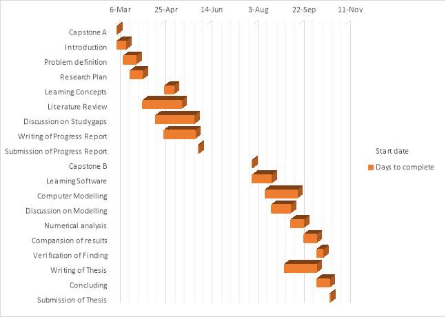
Capstone progress plan and proposed timeline
Cite This Work
To export a reference to this article please select a referencing stye below:
Related Services
View all


Related Content
All TagsContent relating to: "Engineering"
Engineering is the application of scientific principles and mathematics to designing and building of structures, such as bridges or buildings, roads, machines etc. and includes a range of specialised fields.
Related Articles

DMCA / Removal Request
If you are the original writer of this dissertation and no longer wish to have your work published on the UKDiss.com website then please: