Assessment of Behaviour of Strong Back Systems in Buildings
Info: 12982 words (52 pages) Dissertation
Published: 19th Nov 2021
Tagged: ConstructionEngineering
CHAPTER 1: INTRODUCTION
1.1 GENERAL BACKGROUND
Buildings are often subjected to lateral loads like earthquake, wind etc. So it is necessary to provide additional lateral load resisting systems to them in order to ensure safety. There are different types of lateral load resisting systems. Bracings are generally used in framed structures for this purpose. Bracings are generally classified as concentrically braced frames, eccentrically braced frames and knee braced frames. These are conventional systems.
It is well-known that in strong earthquake ground shaking, conventional steel concentrically braced frames are liable to form a weak-story mechanism. This concentration of deformations in one or a number of stories intensifies damage to braces at these levels, resulting in larger non-structural and structural damage at these levels, and premature rupture of the braces, compared to systems with more uniform distribution of harm over height. Weak stories also are likely to possess vital residual displacements, which may be expensive or unfeasible to repair.
It is desirable to enhance the ability of concentric braced frames to avoid concentration of deformations and damage in a few stories. If a system is able to mitigate soft or weak story behaviour, the peak deformation demands on individual braces and maximum residual displacements might be reduced. Several approaches have been explored by various researchers to reduce damage concentration and achieve smaller residual displacement. These systems include:
- Zipper or vertical tie bar systems,
- Tied to ground frames, and
- Strong back systems (SBS).
This study is concentrated on the behaviour of Strong Back System and is explained in detail on successive chapters. In this thesis work, a detailed study has been conducted on different types of bracing systems which include comparative study of different conventional bracing systems, comparative study of some new braced frames and finally a detailed analysis on different configurations of strong back system and hence to propose a best suitable bracing system which mitigates damage concentrations in steel braced frames.
1.2 OBJECTIVES
The primary objective of the thesis is:
To propose a better configuration of SBS which efficiently mitigates the damage concentration in steel braced frames.
To achieve this primary objective, following secondary objectives should be considered.
(i) Comparative study of different conventional bracing systems
(ii) Comparative study of X-CBF with Zipper frames and SBS
(iii) Study on different configurations of SBS
1.3 SCOPE
Buildings are often subjected to lateral loads like earthquake, wind etc. So it is necessary to provide additional lateral load resisting systems to them inorder to ensure safety. Many of the lateral load resisting systems used nowadays are prone to cause damage concentrations in single storeys resulting in ultimate collapse by soft storey mechanism. So it is very necessary to study the effect of different lateral load resisting bracing systems to distribute the inter storey drift more evenly and thereby mitigating the damage concentrations in a particular storey. This study will give an idea about the behaviour of different conventional and innovative bracing systems and thus the most efficient system can be found out.
1.4 SCHEME OF PROJECT WORK
- Literature review
- Validation of SBS with the values from appropriate literature
- Comparative study of different conventional bracing systems under linear static lateral load cases
- Comparative study of concentric X braced frame with Zipper frames and SBS under linear and non-linear static lateral load cases
- Study on different configurations of SBS under linear/non-linear static and dynamic load cases
- Propose a better configuration of SBS which efficiently mitigates the damage concentration in steel braced frames
CHAPTER 2: LITERATURE SURVEY
2.1 THEORETICAL INVESTIGATIONS
Various literatures have been studied regarding different types of bracing systems, modelling features, analysis types and interpretations etc. and are included in this chapter.
2.1.1 Types of bracing systems
Researches about different types of bracing systems have been started a long time back. Various literatures are available regarding conventional concentric, eccentric and knee braced frames which are explained in this chapter.
Concentrically braced frames
Concentrically braced frames (CBF) are conventionally designed braced frames in which the centre lines of the bracing members cross at the main joints in the structure, thus minimising residual moments in the frame. The pros and cons of braced frames are essentially the opposite of moment frames; they provide strength and stiffness at low cost but ductility is likely to be limited and the bracing may restrict architectural planning.
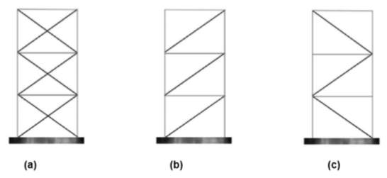
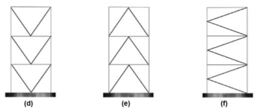
Fig. 2.1: Examples of bracing schemes for CBF: (a) X braced; (b) diagonally braced; (c) alternative diagonally braced; (d) V braced; (e) inverted V-braced; and (f) K-braced (http://www.sefindia.org/forum/files/steel_bracings_146.pdf)
Eccentrically braced frames and Knee-braced frames
In eccentrically braced frames (EBF), some of the bracing members are arranged so that their ends do not meet concentrically on a main member, but are separated to meet eccentrically.
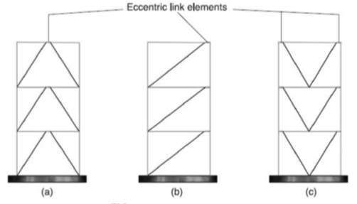
Fig. 2.2 Different configurations of EBF (http://www.sefindia.org/forum/files/steel_bracings_146.pdf)
The eccentric link element between the ends of the braces is designed as a weak but ductile link which yields before any of the other frame members. It therefore provides a dependable source of ductility and, by using capacity design principles, it can prevent the shear in the structure from reaching the level at which buckling occurs in any of the members. The link element is relatively short and so the elastic response of the frame is similar to that of the equivalent CBF. The arrangement thus combines the advantageous stiffness of CBFs in its elastic response, while providing much greater ductility and avoiding problems of buckling and irreversible yielding which affect CBFs in their post-yield phase. Arrangements such as (a) and (b) in Fig 2.2 also have architectural advantages in allowing more space for circulation between bracing members than their concentrically braced equivalent.
An alternative arrangement with similar characteristics is the knee-braced frame. The yielding element here is the ‘knee brace’, which remains elastic and stiff during moderate earthquakes, but yields to provide ductility and protection from buckling in extreme events. Unlike the link in the EBF, the knee brace does not form part of the main structural frame, and could be removed and replaced if it is damaged in an earthquake.
Fig. 2.3 Knee Braced Frame (http://www.sefindia.org/forum/files/steel_bracings_146.pdf)
New systems
With advances in braced frame technology, new systems with higher earthquake resistance are coming into existence. According to Khatib (1988), in strong earthquake ground shaking, conventional steel concentrically braced frames are liable to form a weak-story mechanism. This concentration of deformations in one or a number of stories intensifies damage to braces at these levels, resulting in bigger non-structural and structural damage at these levels, and premature rupture of the braces, compared to systems with more uniform distribution of damage over height. Weak stories also are likely to possess vital residual displacements, which might be expensive or impossible to repair.
Over the years, researchers and engineers have explored many ideas in an attempt to improve the behaviour of braced frame systems. An obvious example is the development of buckling-restrained braces (Watanabe et al. 1988). This kind of brace significantly improves the hysteresis behaviour and the energy-dissipation capacity at the component level (Watanabe et al. 1988; Kalyanamaran et al. 1998, 2003; Chen et al. 2001; Mahin et al. 2004; Lai and Tsai 2004; Lai et al. 2004).
It is desirable to provide CBF with improved capabilities to avoid damage concentrations in a few stories. If a system is able to reduce weak-story behaviour, the peak deformation demands on individual braces and maximum residual displacements might be reduced. Several approaches have been followed to modify the system behaviour of braced frames to develop large deformation capacity, reduce damage concentration, and achieve smaller residual displacement. These systems include: (1) dual systems, where a moment frame is used in addition to the braced frame; (2) zipper or vertical tie-bar systems; (3) rocking/uplifting systems; and (4) masted or strong-back hybrid systems.
Previous research on reducing weak story behaviour in braced frame systems by Khatib et al. (1988) designed zipper braced frame systems and tie-bar-to-ground braced frame systems to prevent weak-story mechanisms. The responses of these systems were compared with the systems shown in figure 2.4. In zipper frame system, the unbalanced force at the middle of a chevron brace pattern would generally displace the beam intersected by the braces in the vertical direction. This vertical movement would be transferred to the floors above and below with the addition of the vertical strut. In these systems, yielding may occur on both sides of the central strut either by tensile yielding or through buckling. In the tie-bar-to-ground system, the unbalanced forces simply accumulated, requiring that the vertical tie bar carry large forces. Its size increased as a result, and it simply became another column in the system. That is, the system became a two-bay frame with a single diagonal brace in each bay.
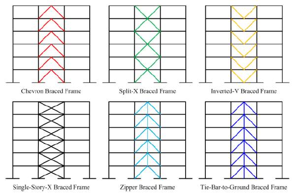
Fig. 2.4: Illustration of different braced frame systems (Khatib et al., 1988).
Building on the ideas related to the tied eccentrically braced frames (Martini et al. 1990), the continuous leaning columns by MacRae et al. (2004), and uplifting/rocking braced frames, a modified zipper bracing configuration has been proposed by Canadian researchers where a vertical strut was provided along the middle of a braced bay; framing in one half of the bay along with the vertical strut remained elastic and deformed like a very strong column or mast along with inelastic action in conventional braces or BRB was permitted in the other half of the bay (Tremblay 2003). To achieve a uniform distribution of drifts over the height of the building, the half of the braced bay that remains essentially elastic acts like a vertical elastic truss or strong back. They found that such frames are cost effective along with better performance compared to traditional braced frames.
2.1.2 Strong Back System
Strong Back System is a hybrid system based on the strong-back truss system by Mahin and Lai. Here, a vertical truss is incorporated that remains elastic within a braced bay or system which imposes a nearly uniform story deformation over the height of the frame (see Figure 2.5). Other possible bracing configurations and strong-back spines are shown in Figure 2.6. The braces used in the system could be either conventional, buckling restrained, or self-centering braces. With proper sizing of the strong back mast system, the designer may have greater flexibility in locating and orienting the braces that yield. This system is not limited to vertical trusses, and other essentially elastic systems, such as steel or reinforced concrete structural walls, large plate girders, and so on, could be used for the strong back mast. For braces with significant differences in tension and compression capacities, it is expected that the overall structural system for a structure would include two strong back bays along each frame line so that an equal number of yielding braces at a floor are loaded in tension and compression.
This dual system can theoretically distribute the inter story drift more evenly. The conventional brace sections respond elastically and the BRB sections yield first. This innovative dual structural system – the strong back system has very little experimental testing and design procedures. Also, the most effective ratios of sizes, shapes, and orientations of the differing braces are still largely unknown. Additional research into these topics is essential.
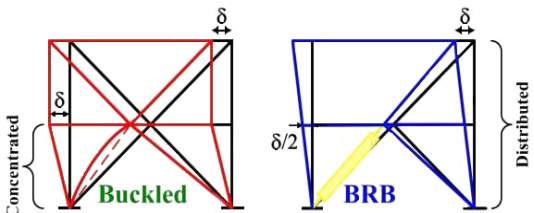
Strong Back BF
Conventional BF
Fig. 2.5 Comparison of CBF drifts with and without strong-back concept (Jiun-Wei Lai, 2013)
The validation of SBS has been conducted from the report by Ray Hooft (2010). That project consists of a series of preliminary analyses on strong back system. The elastic behaviour of the proposed system was investigated by performing elastic analysis in the FE software SAP2000 in a regular two-story model building. To examine the effects on system lateral stiffness, different steel core areas of BRB and conventional wide flange braces were selected. To analyse the performance of different configurations, brace-to-beam intersection points were varied. Inter-storey drift was the primary result of note due to the strong back system’s potential of uniformly distributing this drift. Analysis results show that if designed properly, the proposed dual system can deform uniformly along the height of the building. It is expected that, under extreme loading events the inelastic behaviour of the strong back system has higher potential than systems in use today to prevent the soft-story mechanism. Hence, further nonlinear analysis on this new system is suggested.
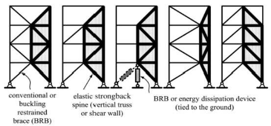
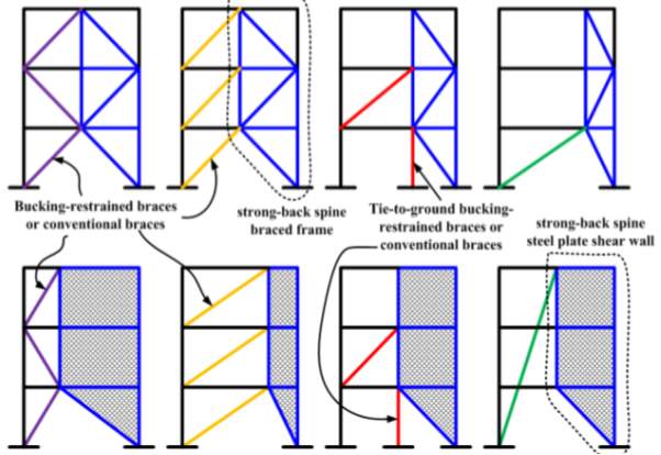
Fig. 2.6 More possible strong-back configurations with different spine systems (Jiun-Wei Lai, 2013)
Later in 2014, Jiun-Wei Lai et al. combined SBS with the aspects of a traditional CBF with a mast to form a hybrid system to achieve improved seismic performance. During severe seismic excitations, the mast acts like a strong back to help resist the tendency of CBF to concentrate damage in one or a few stories. The purpose of the SBS is to promote uniform story drifts over the height of a frame. Analyses was carried out by considering a variety of earthquake excitations on three SBS prototypes and are compared with responses for three other braced frame systems. From the results it is clear that the SBS can effectively reduce the deformation concentrations using the proposed design strategy. The economic feasibility of incorporating the SBS for newly constructed buildings located in seismically active regions is demonstrated by a simplified cost analyses.
2.1.3 Modelling
SBS consist of elastic part and inelastic part. Elastic part is made up of conventional braces or Steel Plate Shear Wall (SPSW). Inelastic part can be made up of Buckling Restrained Braces or any other energy dissipation devices like damper braces. Modelling of these components in finite element software requires proper behavioural input data. Various literatures have been studied which models similar components and are described below.
A literature by Mahin (2010) briefly summarizes his on-going research about concentrically braced steel frames that are widely used in North America. In the analytic phase, a series of nonlinear dynamic analyses and parameter studies are carried out to improve better understanding of the seismic behaviour of concentrically braced frames to identify improved performance based design and analysis procedure. Test results and experimental observations of the braced frame specimens using square and round hollow structural section as bracing components are presented in this paper. Similarly in the research conducted by Ray Hooft (2010), conventional braces are modelled using hollow and wide flange steel sections.
Studies by Thorburn et al (1983) and later by Driver et al (1998) indicated that steel shear wall can be modelled as truss members as shown in Figure 2.7 (a) by using a series of diagonal tension struts positioned at almost 45-degree angles. By replacing the shear wall with these struts, the resulting steel structure can be analysed using currently available computer analysis software, such as SAP2000 Nonlinear and inelastic pushover programs (CSI, 2000). A “multi-angle strip model” for steel plate shear walls was proposed by Rex, Ventura and Prion (2000). The researchers have shown that the predictions of analyses are reasonable close to the test results using a non-linear analysis program and the model shown in Figure 2.7 (b). But the strip model underestimates both the initial stiffness and the load carrying capacity of SPSW structures in comparison to the shell element method. However, this approach can be very tedious for high-rise building design. The analysis for high-rise buildings can be simplified by using elastic orthotropic plate elements (Ignasius F. Seilie, 2005).
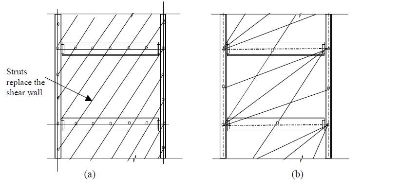
Fig. 2.7 Two proposed strut models:
(a) Thorburn et al., (1983) and (b) Rezaii et al., (2000)
Due to the configuration of the brace elements BRBF systems are unique. BRB consist of two major components: axial stress resisting steel core and the buckling stress resisting outer concrete filled steel casing which restrains the steel core from buckling thereby developing almost uniform axial strains in tension and compression. BRBF have compression yielding similar to tension yielding behaviour with full, balanced hysteresis loops. The post- bucking load imbalance inherent in the conventional braced frames is eliminated by the near equal tension and compression capacities of BRBF’s.
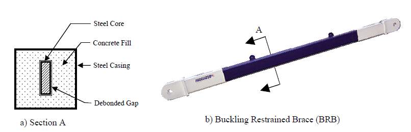
Fig.2.8 Typical BRBF element (Saif Hussain et al., 2005)
In the study conducted by Ray Hooft (2010), BRBs were modelled as solid sections under the assumption that BRB failure would only be caused by exceeding the yielding capacity and not by buckling. But while considering the non-linear static and dynamic analysis, exact behaviour has to be applied. So BRB can be modelled as multi-linear plastic link element with kinematic hysteresis behaviour in SAP2000. Similar modelling can be seen in the study by Mario D’Aniello (2008). Properties of buckling restrained braces are taken from Star Seismic provisions for the study conducted by Nikhil D. Sontakke (2016). Zhongliang Xie (2015) took modelling parameters of the BRBs from CoreBrace LLC.
As per Douglas Taylor, fluid viscous dampers operate on the principle of fluid flow through orifices. A stainless steel piston travels through silicone oil filled chambers. The force/velocity relationship for this kind of damper can be characterized as,
(2.1)
F=CV∝
Where, F is the output force, V the relative velocity across the damper, C is the damping coefficient and α is a constant exponent which is usually a value between 0.3 and 1.0. Fluid viscous dampers have the unique ability to simultaneously reduce both stress and deflection within a structure subjected to a transient. A photograph of a typical damper installation is provided in Figure 2.9.
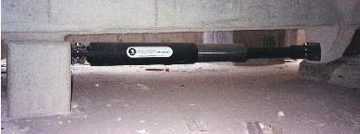
Fig. 2.9 Arrowhead Regional Medical Center Damper installation
(http://docplayer.net/22485888-Fluid-viscous-dampers-used-for-seismic-energy-dissipation-in-structures.html)
Considering the computed features, V. Sadeghi Balkanloua (2013) modelled the viscous damper using SAP2000 software with N-link non-linear elements at damper position. SAP2000 software uses parallel and series systems of spring and damper in linear and non-linear analyses, respectively (Figure 2.10).
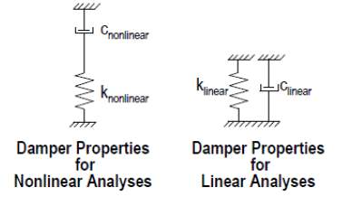
Fig.2.10 Damper element in SAP2000 software (V. Sadeghi Balkanloua, 2013)
Since viscous damper system will be modelled as pure stiffness-free damping behaviour (stomatal viscous damper), stiffness of damper element will be considered zero in order to reach the pure damping in linear analyses. To eliminate the spring effect, its stiffness should be considered significantly high in non-linear analyses where series model of spring damper is used. In time history analyses where non-linear specifications of damper are used, acceptable results will be achieved if damping coefficient of damper to non-linear spring stiffness ratio is selected one or two degrees smaller than time step of the analysis.
CHAPTER 3: METHODOLOGY
3.1 GENERAL
A proper methodology has been followed during the entire thesis work inorder to fulfil all the primary and secondary objectives. Figure 3.1 shows the chart indicating the outline of methodology.
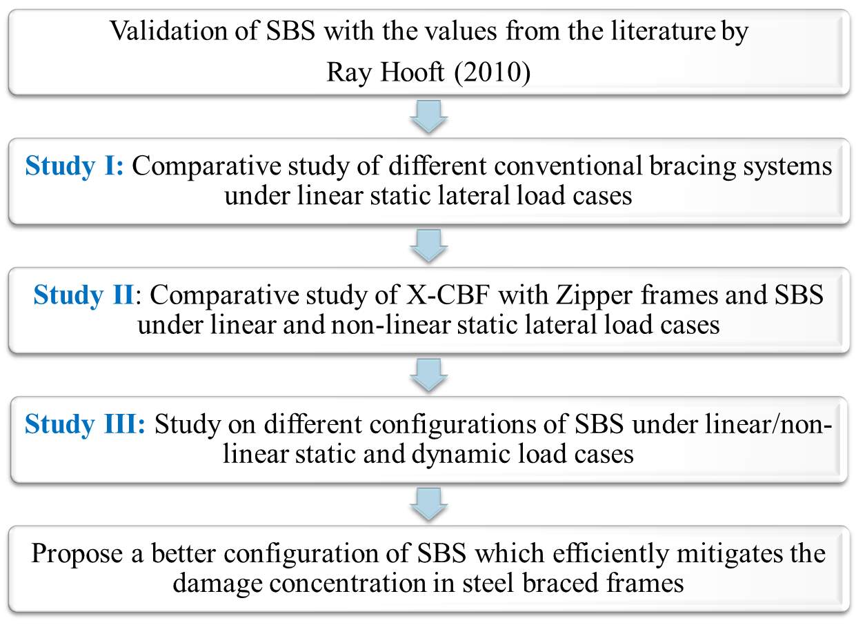
Fig. 3.1: Outline of methodology
Initially a detailed literature study has been conducted regarding different types of bracing systems, modelling features, analysis types and interpretations etc. and is included in previous chapter. After that, for the first phase of the thesis, validation has been conducted using the values obtained from the literature “Preliminary study of the strong back system: Preventing the soft story mechanism” by Ray Hooft (2010) and is discussed in the following chapter.
For the second phase of the thesis, SBS is compared with other bracing systems to prove that this is a versatile system in resisting lateral loads and thereby mitigating damage concentrations in steel frames. This phase is divided into two chapters. In first chapter, different conventional concentric and eccentric braces frames are modelled using FE software SAP2000 and are analysed under linear static lateral loads. The results are compared to find out the outperforming conventional bracing system. From those results, the best performing brace under given conditions is selected and it is compared with new systems like zipper frames and SBS by performing linear and non-linear static load conditions in the next chapter.
As per figure 2.6, more possible strong-back configurations with different spine systems are suggested in literatures. The performance of those systems should be studied further to find out the most efficient strong back system. Fourteen different strong back spine configurations are selected and linear and non-linear static and dynamic analysis has been conducted on those configurations. From those results, an outperforming configuration has to be proposed which mitigates damage concentrations efficiently in steel braced frame systems.
3.2 TYPES OF ANALYSIS
Different types of analysis used for the present study is explained here. Analysis can be done by considering linear or non-linear behaviour of structures. In that, loading can be either static or dynamic. The complete advantage of strong back system can be estimated only by considering the non-linear behaviour. Also, inorder to analyse the seismic performance of these systems, dynamic loading should be considered. So a series of linear static, non-linear static pushover analysis, response spectrum analysis and linear and non-linear time history analysis are to be conducted on these models inorder to evaluate the complete performance in resisting lateral loads.
3.3.1 Equivalent Static Analysis
All design against seismic loads must consider the dynamic nature of the load. However, for simple regular structures, analysis by equivalent linear static methods is often sufficient. This is permitted in most codes of practice for regular, low- to medium-rise buildings. It begins with an estimation of base shear load and its distribution on each story calculated by using formulas given in the code. Equivalent static analysis can therefore work well for low to medium-rise buildings without significant coupled lateral-torsional modes, in which only the first mode in each direction is considered. Tall buildings (over, say, 75 m), where second and higher modes can be important, or buildings with torsional effects, are much less suitable for the method, and require more complex methods to be used in these circumstances.
3.3.2 Non-linear Static Pushover Analysis
A structure is subjected to a monotonically increasing pattern of lateral loads which represents the inertial forces which would be experienced by the structure when subjected to ground shaking in a pushover analysis. Various structural elements may yield sequentially under incrementally increasing loads. The structure experiences a loss in stiffness consequently at each event. Using a pushover analysis, a characteristic non-linear force displacement relationship can be determined. It is necessary for the following considerations:
- Pushover analysis is a nonlinear static analysis used mainly for seismic evaluation of framed building.
- Seismic demands are computed by nonlinear static analysis of the structure, which is subjected to monotonically increasing lateral forces with an invariant height-wise distribution until a target displacement is reached.
- It is also necessary for evaluating the seismic adequacy of existing buildings.
Nonlinear static pushover analysis can provide an insight into the structural aspects, which control performance during severe earthquakes. The analysis provides data on the strength and ductility of the structure, which cannot be obtained by elastic analysis. By pushover analysis, the base shear versus top displacement curve of the structure, usually called capacity curve, is obtained. Based on the capacity curve, a target displacement which is an estimate of the displacement that the design earthquake will produce on the building is determined. The extent of damage experienced by the structure at this target displacement is considered representative of the damage experienced by the building when subjected to design level ground shaking.
Key Elements of Pushover Analysis
- Definition of plastic hinges: In SAP2000, nonlinear behaviour is assumed to occur within a structure at concentrated plastic hinges. The default types include an uncoupled moment hinges, an uncoupled axial hinges, an uncoupled shear hinges and a coupled axial force and biaxial bending moment hinges.
- Definition of the control node: Structure’s displacement is monitored using control node. The capacity (pushover) curve of the structure is the displacement versus the base-shear forms.
- Developing the pushover curve which includes the evaluation of the force distributions. It is important to consider a force displacement equivalent to the expected distribution of the inertial forces to have a displacement similar or close to the actual displacement due to earthquake.
- Estimation of the displacement demand: This is a difficult step when using pushover analysis. The control is pushed to reach the demand displacement which represents the maximum expected displacement resulting from the earthquake intensity under consideration, which is calculated in Response spectrum analysis.
Response demand versus capacity is the main output of a pushover analysis. The structure has a good resistance if the demand curve intersects the capacity envelope near the elastic range as shown in Fig.3.2 (a). The structure will behave poorly during the imposed seismic excitation and need to be retrofitted to avoid future major damage or collapse if the demand curve intersects the capacity curve with little reserve of strength and deformation capacity as shown in Fig.3.2 (b). We have to decide whether to do perform seismic retrofitting or rehabilitation depending on the weak zones that are obtained in the pushover analysis.
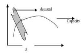
Safe design Unsafe design
Fig.3.2 Typical seismic demand versus capacity (Abhijeet A. Maske, 2014)
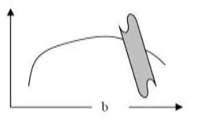
Under incrementally increasing loads some elements may yield sequentially. Consequently, at each event, the structures experience a stiffness change. Table 3.1 shows the performance level of building based on the hinge formation and it is shown graphically in figure 3.3.

Fig 3.3 Different stages of plastic hinge (Mohammed Ismaeil, 2015)
Table 3.1 Performance level of building (Mohammed Ismaeil, 2015)
| Level | Abbreviation | Description |
| Operational | B | Very light damage, no permanent drift, structure retains original strength and stiffness, all systems are normal |
| Immediate Occupancy | IO | Light damage, no permanent drift, structure retains original strength and stiffness, elevator can be restarted, Fire protection operable |
| Life Safety | LS | Moderate damage, some permanent drift, some residual strength and stiffness left in all stories, damage to partition, building may be beyond economical repair |
| Collapse Prevention | CP | Severe damage, large displacement, little residual stiffness and strength but loading bearing column and wall function, building is near collapse |
3.3.3 Response Spectrum Analysis
Response-spectrum analysis (RSA) is a linear-dynamic statistical analysis method which measures the contribution from each natural mode of vibration to indicate the likely maximum seismic response of an essentially elastic structure (https://wiki.csiamerica.com/display/kb/Modal+analysis). Response-spectrum analysis provides insight into dynamic behaviour by measuring pseudo-spectral acceleration, velocity, or displacement as a function of structural period for a given time history and level of damping ( https://wiki.csiamerica.com/display/kb/Damping). It is practical to envelope response spectra such that a smooth curve represents the peak response for each realization of structural period.
Response-spectrum analysis is useful for design decision-making because it relates structural type-selection to dynamic performance. Structures of shorter period experience greater acceleration, whereas those of longer period experience greater displacement. Structural performance objectives should be taken into account during preliminary design and response-spectrum analysis.
3.3.4 Time History Analysis
Time-history analysis provides for linear or nonlinear evaluation of dynamic structural response under loading which may vary according to the specified time function (https://wiki.csiamerica.com/display/kb/Time+function). Dynamic equilibrium equations, given by Ku(t)+C d/dt u(t)+Md2/dt u(t)=r(t), are solved using either modal or direct-integration methods (https://wiki.csiamerica.com/display/kb/Directintegration+timehistory+analysis). Initial conditions may be set by continuing the structural state from the end of the previous analysis. Additional notes include:
- Step Size – Direct-integration methods are sensitive to time-step size, which should be decreased until results are not affected.
- HHT Value – A slightly negative Hilber-Hughes-Taylor alpha value is also advised to damp out higher frequency modes, and to encourage convergence of nonlinear direct-integration solutions.
(https://wiki.csiamerica.com/display/kb/Time-history+output-acceleration+accuracy)
- Nonlinearity – Material and geometric nonlinearity, including P-delta and large-displacement effects, may be simulated during nonlinear direct-integration time-history analysis.
- Links – Link objects capture nonlinear behaviour during modal (FNA) applications.
Fast Nonlinear Analysis (FNA) is a modal analysis method useful for the static or dynamic evaluation of linear or nonlinear structural systems. Because of its computationally efficient formulation, FNA is well-suited for time-history analysis, and often recommended over direct-integration applications. During dynamic-nonlinear FNA application, analytical models should:
- Be primarily linear-elastic.
- Have a limited number of predefined nonlinear members.
- Lump nonlinear behaviour within link objects.
In addition to nonlinear material force-deformation relationships, these link objects may simulate concentrated damping devices, isolators, and other energy-dissipating technologies. If fuse mechanisms are not integral to the design intention, an initial elastic analysis may reveal locations where inelasticity is likely to occur. However, it is always best to predefine inelastic mechanisms such that their design may provide for sufficient ductility, while elastic systems are ensured sufficient strength. Capacity Design provides for a more reliable model and a better-performing structure.
The efficiency of FNA formulation is largely due to the separation of the nonlinear-object force vector RNL(t) from the elastic stiffness matrix and the damped equations of motion, as seen in the fundamental equilibrium equation of FNA, expressed as:
Müt+Cu̇t+Kut+RNLt=R(t) (3.1)
Stiffness- and mass-orthogonal Load-Dependent Ritz Vectors represent the equilibrium relationships within the elastic structural system. At each time increment, the uncoupled modal equations are solved exactly, while forces within the predefined nonlinear DOF, indexed within RNL(t), are resolved through an iterative process which converges to satisfy equilibrium. Following this procedure, FNA is an efficient and accurate dynamic-nonlinear application which satisfies equilibrium, force-deformation, and compatibility relationships (https://wiki.csiamerica.com/pages/viewpage.action?pageId=9536464).
CHAPTER 4: VALIDATION
4.1 GENERAL
For the first phase of the thesis, validation has been conducted using the values obtained from the literature “Preliminary study of the strong back system: Preventing the soft story mechanism” by Ray Hooft (2010).
4.1.1 Model Building Selection
The model building was selected to be a simple two-story office building in downtown Berkeley. The plan dimension is 120 feet x 180 feet with 30 foot wide bays and 13 foot tall storeys. There is one set of braces per storey in outer bay on each side as shown in figure 4.1.
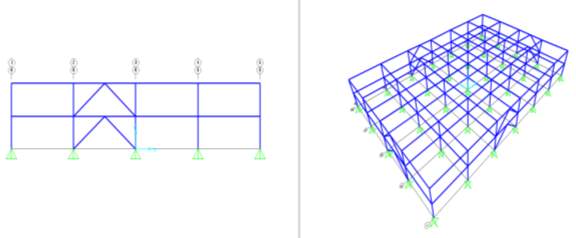
Fig. 4.1: Profile and 3 D views of model building
4.2 MODELLING
The load combination of interest was 1.2DL+1.0EQ during analysis by Ray Hooft. The analysis was performed in the elastic range of brace response, so BRBs were modelled as solid sections in order to simplify the procedure, under the assumption that BRB failure would only be caused by exceeding the yielding capacity and not by buckling. The conventional braces were modelled by simply utilizing the pre-existing wide flange sections in SAP2000 (Ray Hooft, 2010).
4.3 LOADING
The loading was calculated for this two-story building using AISC-360-05. Equivalent lateral force (ELF) analysis was used to determine earthquake loading, with seismic base shear from FEMA-450 provisions equation 5.2-1 equalling 656 kips. This force was rounded and distributed 260 kips at the bottom floor and 400 kips at the top floor. The dead load was applied as a point load at each of the four column-beam connections and was calculated based on loading assumptions from a similar previous test (Lai, 2009). SAP2000 was set to account for the dead load from member weight during analysis. The braces were pinned at both ends with the BRB on the left and the conventional brace on the right with a chevron design (Figure 4.2a). Three different brace length configurations were considered and given the names 25/75, 50/50, and 75/25 for reference (Figures 4.2a, 4.2b, 4.2c).
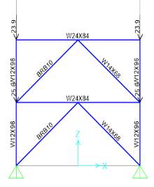
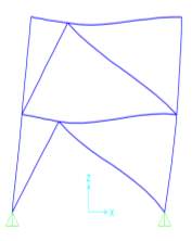
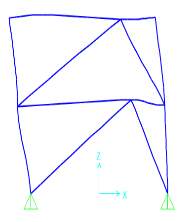
(a) (b) (c)
Fig. 4.2 Different Brace Configurations: (a) 50/50 configuration before analysis with DL; (b) 25/75 configuration after analysis of L-R EQ loading; (c) 75/25 configuration after analysis of R-L EQ loading
4.4 RESULTS AND DISCUSSION
Inter storey drift ratio has been calculated for the three different configurations with both direction loading. The obtained values are compared with the values given in the literature and the percentage deviation is calculated as shown in Table 4.1.
Table 4.1 Calculation of inter storey drift ratio
| INTER STOREY DRIFT RATIO | ||||
| 50/50 configuration | 25/75 configuration | 75/25 configuration | ||
| L-R EQ loading | Obtained Value | 1.58 | 1.07 | 1.73 |
| Value from journal | 1.518 | 1.12 | 1.69 | |
| % deviation | 3.9 | 4.4 | 2.31 | |
| R-L EQ loading | Obtained Value | 1.52 | 1.84 | 1.36 |
| Value from journal | 1.519 | 1.7 | 1.3 | |
| % deviation | 0.65 | 7.6 | 4.4 | |
Most of the obtained values are comparative to the values given in the literature.
CHAPTER 5: ANALYSIS OF DIFFERENT CONVENTIONAL BRACING SYSTEMS
5.1 GENERAL
For the second phase of the thesis, SBS is compared with other bracing systems to prove that this is a versatile system in resisting lateral loads and thereby mitigating damage concentrations in steel frames. This phase is divided into two chapters. In this chapter, different conventional concentric and eccentric braces frames are modelled using FE software SAP2000 and are analysed under linear static lateral loads. The results are compared to find out the outperforming conventional bracing system.
5.2 MODELLING
Linear static analysis of different concentric and eccentric brace configurations has been conducted using a 6 m wide 5 bay 4 storeyed frame with 3 m height. There are 10 models developed using the FE software SAP2000, out which 7 are concentric and remaining 3 are eccentric as shown in figure 5.1. Section size of members is proportioned for each model so as to keep the overall weight of the structure almost similar.
(a) Concentric Diagonal braces (b) Concentric Alternate diagonal braces 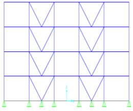
(c) Concentric V braces (d) Concentric Chevron braces
(e) Concentric K braces (f) Concentric X braces
(g) Concentric Split X braces (h) Eccentric Chevron braces
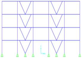
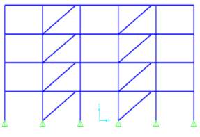
(i) Eccentric V braces (j) Eccentric Diagonal braces
5.3 RESULTS AND DISCUSSION
Lateral deformations of each model are noted and compared after linear static analysis. Roof drift of the models are shown in figure 5.2. Figure 5.3 shows Inter-storey Drift ratio obtained by linear static analysis.
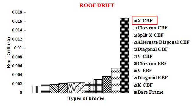
Fig 5.2 Roof Drift values obtained by linear static analysis
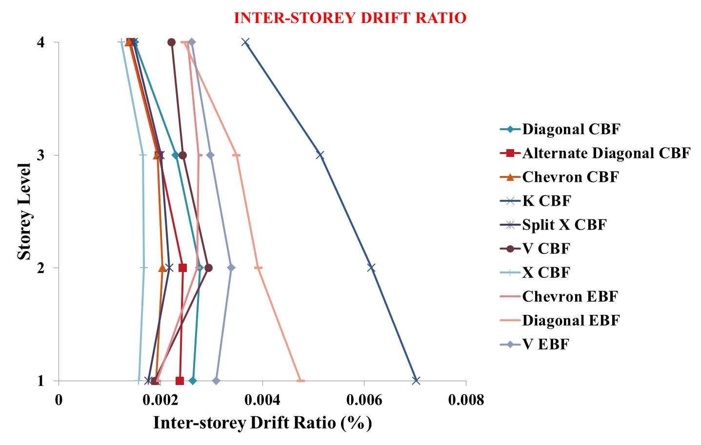
Fig 5.3: Inter-storey Drift ratio obtained by linear static analysis
From the above results, it is clear that X-CBF reduced 90.4% roof drift of bare frame and has less lateral deformations under given conditions and hence performed better when compared to other models.
CHAPTER 6: COMPARATIVE STUDY OF X-CBF WITH ZIPPER FRAMES AND SBS
6.1 GENERAL
From the previous chapter, it is clear that concentric X braced frame is performing better under given conditions. Now, new systems like zipper frames and SBS are compared keeping the concentric X braced frame as benchmark which is described in this chapter.
6.2 MODELLING
5 bay 6 storey frames are adopted for further linear static & non-linear static pushover analysis by keeping the weight of the structure comparable. 3 models are developed using the FE software SAP2000. First one is concentric X braced frame as shown in figure 6.1. Other two models are new systems like Zipper frames and SBS shown in figure 6.2 and 6.3. Buckling restrained braces are modelled as multi-linear plastic link elements with kinematic hysteresis behaviour as shown in figure 6.4. Properties of buckling restrained braces are taken from Star Seismic provisions. Table 6.1 shows the Seismic Design Parameters used for analysis.
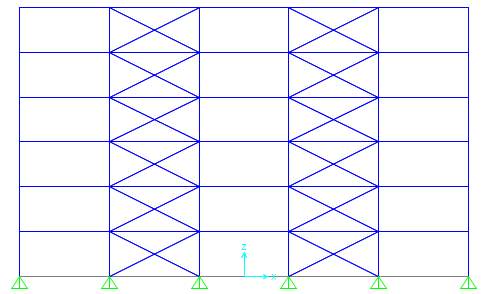
Fig 6.1 Concentric X braced frame
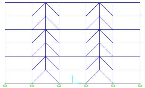
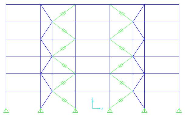
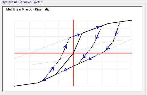
Fig 6.4 Hysteresis Definition sketch of BRB in SAP2000
Table 6.1 Seismic Design Parameters
| Design parameters | Values |
| Governing Code
Importance factor (I) Seismic design category Site class Response modification factor (R) System over strength factor (Ωo) Deflection amplification factor (Cd) S1 (g) SS (g) Fa Fv SD1 (g) SDS (g) |
ASCE-7-2005
1.0 D D 6 2.0 5.0 0.787 2.014 1.0 1.5 0.787 1.343 |
6.3 RESULTS AND DISCUSSION
Linear static & non-linear static pushover analysis has been conducted on each model to study the effect of lateral forces. Lateral deformation and the sequence of plastic hinge formation of each model are noted and compared to reach the conclusions. Fig 6.5 and figure 6.6 shows the graphical representation of Inter-Storey Drift ratio and roof drift obtained by linear static analysis. Fig 6.7 shows the Inter-Storey Drift ratio obtained by non-linear static pushover analysis.
From these graphs, it is clear that SBS shows lesser lateral deformation under linear static loads and the same system sustained more deformation without failure when a push of 0.3048 m is given. Plastic hinge formations of the members in the frame are obtained after conducting static pushover analysis in SAP2000 and are shown in figure 6.8 through 6.10. Performance level of building based on the hinge formation was discussed in literature review.
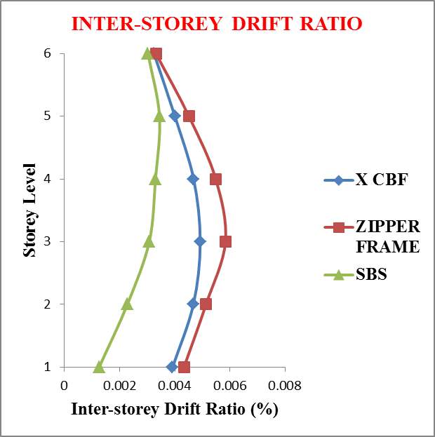
Fig 6.5 Inter-Storey Drift ratio obtained by linear static analysis
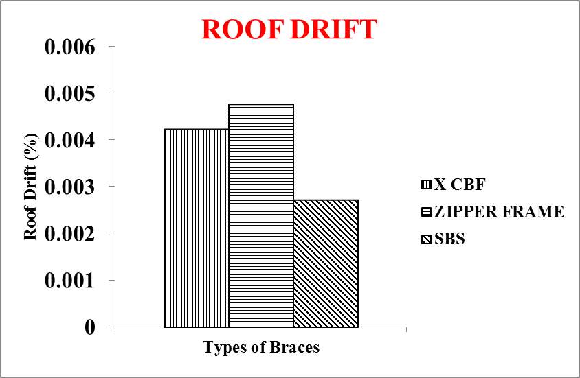
Fig 6.6 Roof Drift obtained by linear static analysis
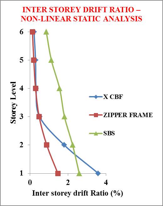
Fig 6.7 Inter-Storey Drift ratio obtained by non-linear static pushover analysis
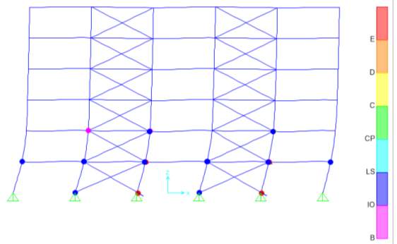
Fig 6.8 Hinge formation after non-linear static pushover analysis of X-CBF
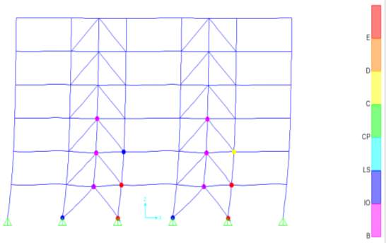
Fig 6.9 Hinge formation after non-linear static pushover analysis of Zipper braced frame
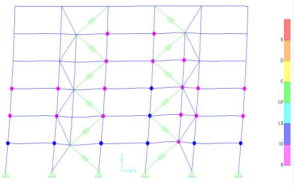
Fig 6.10 Hinge formation after non-linear static pushover analysis of SBS braced frame
From figure 6.8, it is clear that lower stories exhibit soft storey mechanism in Concentric X braced frame resulting in the premature failure of brace members above that storey which is not desirable. Also, Zipper braces reached collapse mechanism at low displacements due to low ductility as shown in figure 6.9 resulting in the premature failure of brace members above that storey which also is not desirable. SBS has uniform storey drift distribution with enough ductility as shown in figure 6.10. SBS has 35.5% decrease in roof drift with respect to X CBF under linear static load condition. Therefore, SBS has better linear and non-linear behaviour when compared to other models. Hence this system outperformed all other bracing systems.
CHAPTER 7: ANALYSIS OF DIFFERENT CONFIGURATIONS OF SBS
7.1 GENERAL
As described in the previous chapter, SBS is found to be efficient in resisting lateral forces. As per figure 2.6, more possible strong-back configurations with different spine systems are suggested in literatures. The performance of those systems should be studied further to find out the most efficient strong back system. Linear and non-linear static and dynamic analysis has been conducted on selected configurations of SBS, which is described in this chapter.
7.1.1 Model Building Selection
A seven-storey model building was used to examine the behaviour of different SBS configurations. The basic model characteristics are shown in Fig. 7.1. Only the four braced bays in each direction were explicitly considered part of the lateral force resisting system. The floor beams are assumed to have typical pin connections to the columns. Each direction has five beam spans and the bay widths are equal to 6 m. Each story is 3.5 m tall. The occupancy of the building is assumed to be that of a typical office building. The soil is designated Site Class D. The building code used for the design of the model was IS 800-2007. Tributary dead load and live load are given as per IS 875 Part I. Load combinations are also given as per Indian Standards.
7.2 MODELLING
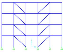
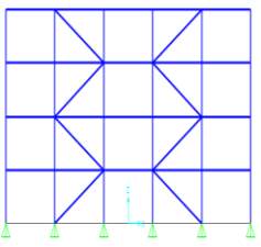
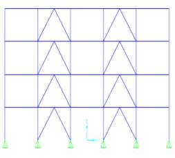
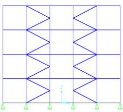
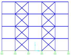
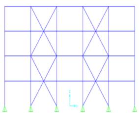
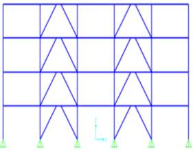
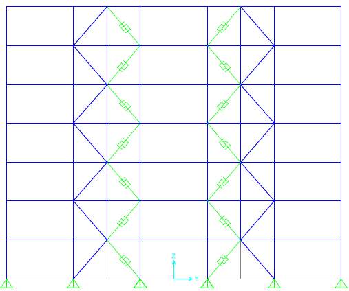
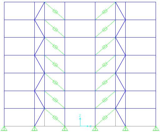
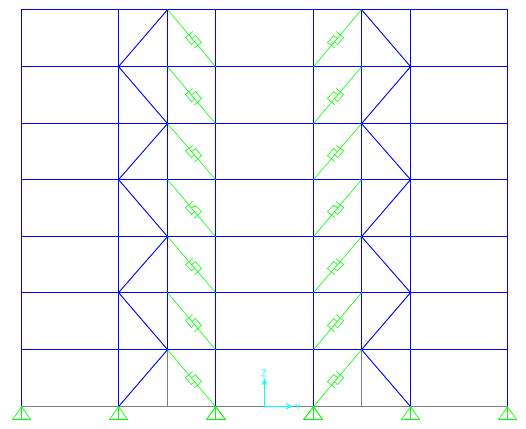
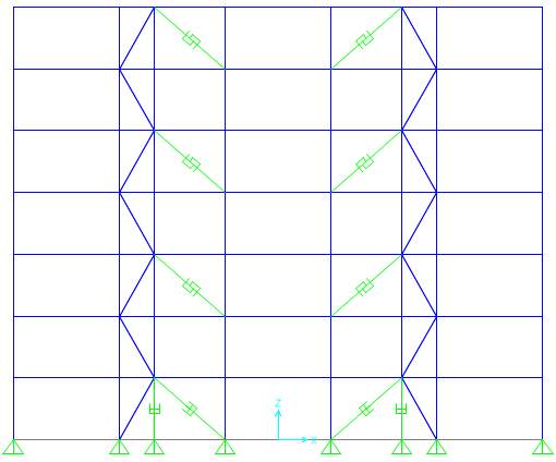
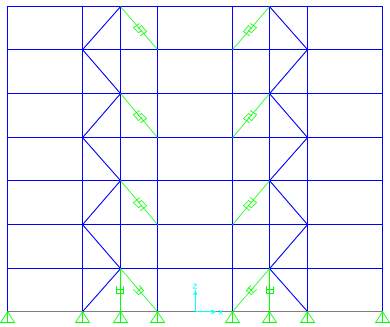
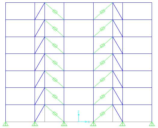
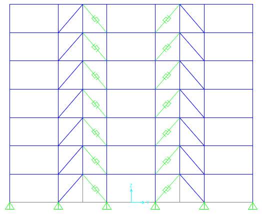
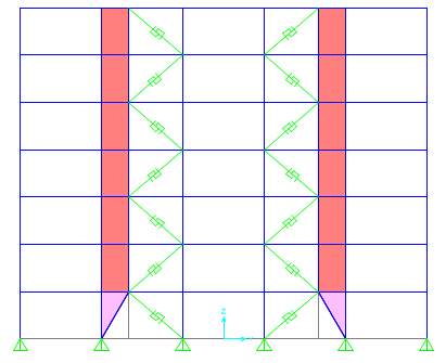
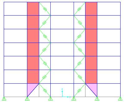
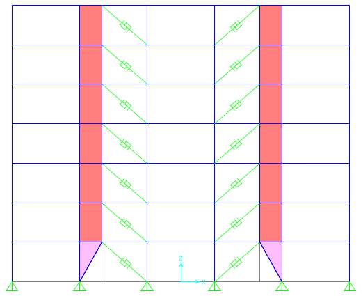
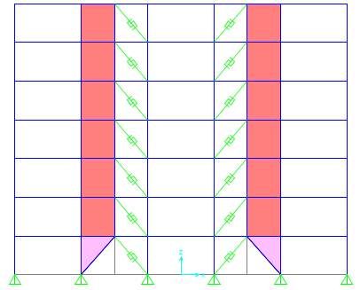
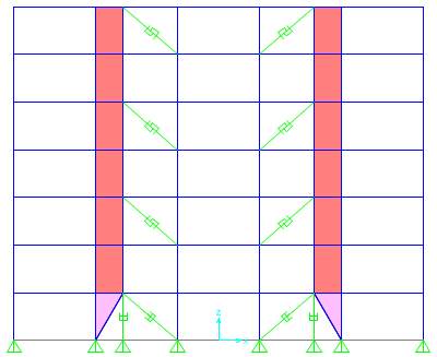
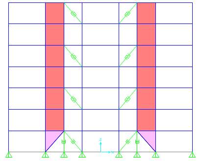
A total of fourteen different configurations of seismic force-resisting strong back systems were selected for this study (Fig. 7.3). Modelling of all configurations has been done using FE software SAP2000. Configurations are classified into two: SBC models with elastic truss part defined by conventional wide flange or hollow sections and SBS models with steel plate shear walls acting as elastic part of strong back mechanism. Intersection of the braces was shifted from the middle of the beam to the one-third point (1/3) for the models designated as ‘a’ which can facilitate proportioning the load to various members in the SBS. In the cases considered herein, the vertical elastic truss portion of the bay is narrower than half the bay width, making the inelastic elements longer so that they have greater length over which to yield. Reducing the inclination of the inelastic braces has the benefit that they can be smaller yet able to resist the same lateral load on the structure. Moreover, for large lateral displacements of the frame, the increased length of the beam in the inelastic portion of the bay will be longer, reducing its shear and the plastic hinge rotations that might form at the ends of the beams. All other models keep midspan intersection (1/2) which is designated as ‘b’ (Figure 7.1).
Each direction of the prototype building had four braced bays with two at each perimeter face, as shown in Fig. 7.2. To ensure a symmetric lateral force-resisting system, the shifted points were aligned about the centreline of the elevation. That is, if one bay has a yielding/buckling braced inclined to the left, the other bay has the corresponding brace inclined to the right. Hysteresis behaviours of conventional buckling braces are typically non-symmetric and severe degradations of compression strengths are usually observed under cyclic loadings. Therefore, BRBs are used in the strong back system outside the vertical spine, as shown in fig. 7.2, since BRBs have nearly symmetric hysteresis loops and stable energy dissipation characteristics.
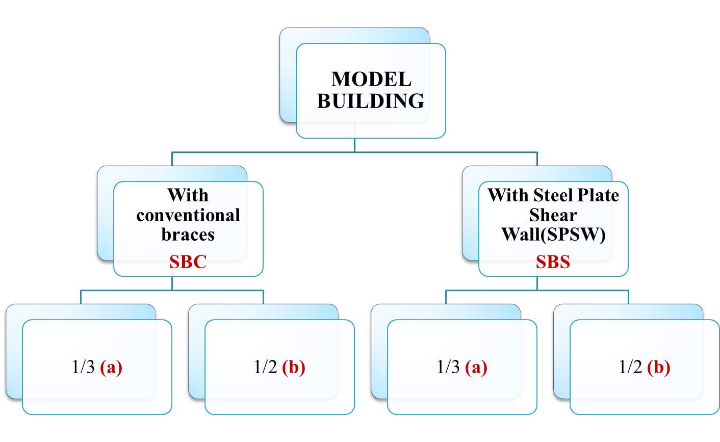
Fig. 7.1 Classification of models
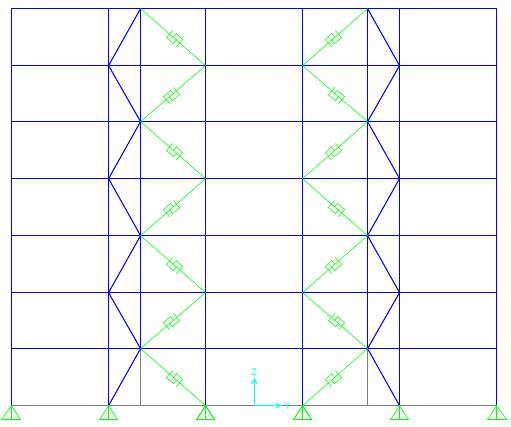
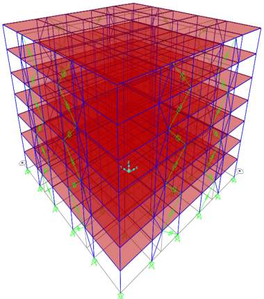
Fig. 7.2 Profile and 3 D views of model building


SBC-1a
SBC-1b
Vertical truss system
BRB


SBC-2b
SBC-2a


SBC-3a
SBC-3b
(Tied to the ground)
Damper
SBC-4a
SBC-4b

SBS-1a
SBS-1b
SPSW system
SBS-2a
SBS-2b
SBS-3b
SBS-3a
Fig. 7.3 Different configurations of Strong Back System
Table 7.1: Key features of selected strong back configurations
|
Model No. |
ID |
Key features |
|
|
SBC-1a | Benchmark
Conventional brace + BRB with 1/3 configuration BRB- Alternate diagonal |
|
|
SBC-1b | Conventional brace + BRB with 1/2 configuration
BRB- Alternate diagonal |
|
|
SBC-2a | BRB- Diagonal with 1/3 configuration
Conventional brace + BRB |
|
|
SBC-2b | BRB- Diagonal
Conventional brace + BRB with 1/2 configuration |
|
|
SBC-3a | BRB- Diagonal in alternate storeys
Conventional brace + BRB + Damper with 1/3 configuration Less no. of elements |
|
|
SBC-3b | BRB- Diagonal in alternate storeys
Less no. of elements Conventional brace + BRB + Damper with 1/2 configuration |
|
|
SBC-4a | BRB- Diagonal
Conventional braces- Diagonal Conventional brace + BRB with 1/3 configuration |
|
|
SBC-4b | BRB- Diagonal
Conventional braces- Diagonal Conventional brace + BRB with 1/2 configuration |
|
|
SBS-1a | SPSW + BRB with 1/3 configuration
BRB- Alternate diagonal |
|
|
SBS-1b | SPSW + BRB with 1/2 configuration
BRB- Alternate diagonal |
|
|
SBS-2a | BRB- Diagonal
SPSW + BRB with 1/3 configuration |
|
|
SBS-2b | BRB- Diagonal
SPSW + BRB with 1/2 configuration |
|
|
SBS-3a | BRB- Diagonal in alternate storeys
SPSW + BRB + Damper with 1/3 configuration Less no. of BRB elements |
|
|
SBS-3b | BRB- Diagonal in alternate storeys
Less no. of BRB elements SPSW + BRB + Damper with 1/2 configuration |
BRB has been modelled as described in the previous chapter. Viscous damper is given as energy dissipating device in respective models. They are modelled as exponential damper using link elements in SAP2000 using the provisions of Taylor devices Inc. Since viscous damper system will be modelled as pure stiffness-free damping behaviour, stiffness of damper element will be considered zero in order to reach the pure damping in linear analyses. To eliminate the spring effect, its stiffness should be considered significantly high in non-linear analyses where series model of spring damper is used. Instead of vertical truss systems used in SBC models, unstiffened steel plate shear wall (SPSW) is used as elastic strong back spine in SBS models. Advantages of using SPSWs in a building is lateral force resisting system compromise stable hysteretic characteristics, high plastic energy absorption capacity and enhanced stiffness, strength and ductility. SPSW can be modelled as strip elements or orthotropic shell elements. As per literature, the strip model underestimates both the initial stiffness and the load carrying capacity of SPSW structures in comparison to the shell element method. Therefore, steel plates are modelled as orthotropic shell elements with 3 mm thickness.
7.3 RESULTS AND DISCUSSION
7.3.1 Equivalent Static Analysis
Linear static analysis has been conducted on the models by considering DL, LL and earthquake loads only. Lateral deformations, inter-storey drift ratio and roof drift of each model have been studied considering the critical load combination and are graphically shown in figure 7.4 and 7.5.
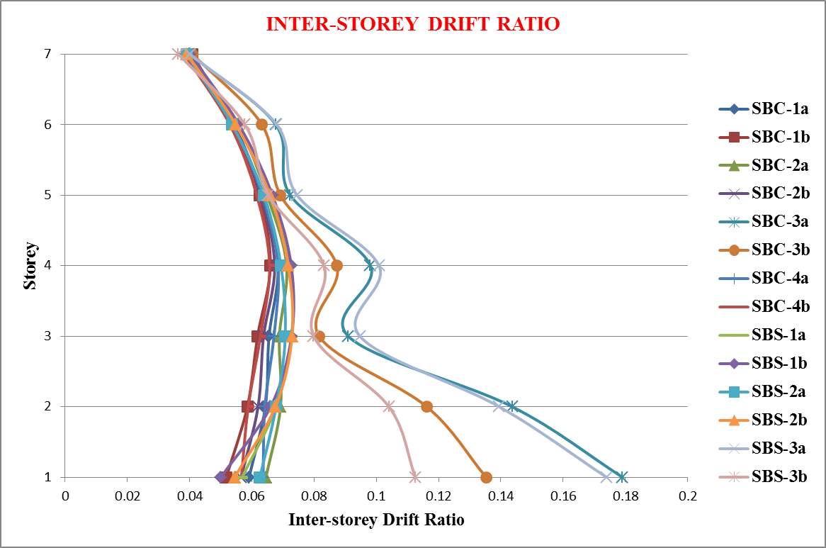
Fig. 7.4: Inter-storey Drift ratio after linear static analysis
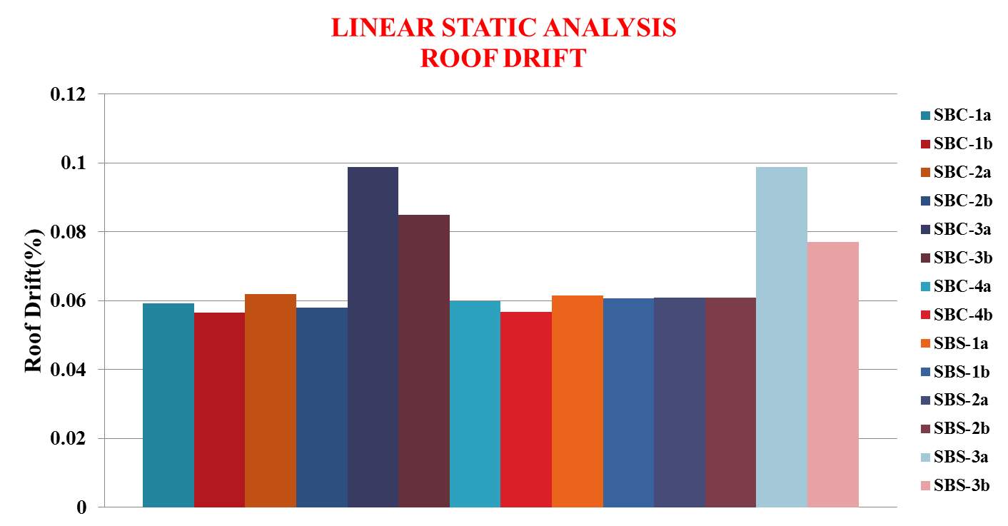
Fig. 7.5: Roof drift after linear static analysis
The following conclusions are obtained from the above results:
- Roof drift was too low for all models
- All models except damper models performed better with an average of 11.9 % decrease in roof drift and uniform inter storey drift ratio
- All damper models have higher roof drift where SBS-3b has comparatively better performance with an increase of 46.48 %.
7.3.2 Non-linear Static Pushover Analysis
Non-linear static pushover analysis has been conducted on each model by giving a push of 2 m on the top corner node of the building after assigning appropriate hinge properties on each member and the lateral deformations are noted. Inter-storey drift ratio and roof drift are graphically plotted and are shown in figure 7.6 and 7.7.
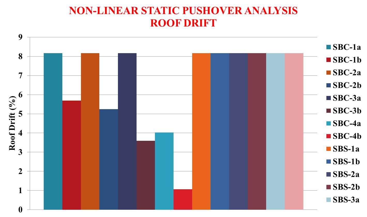
Fig. 7.6: Roof drift after non-linear static analysis
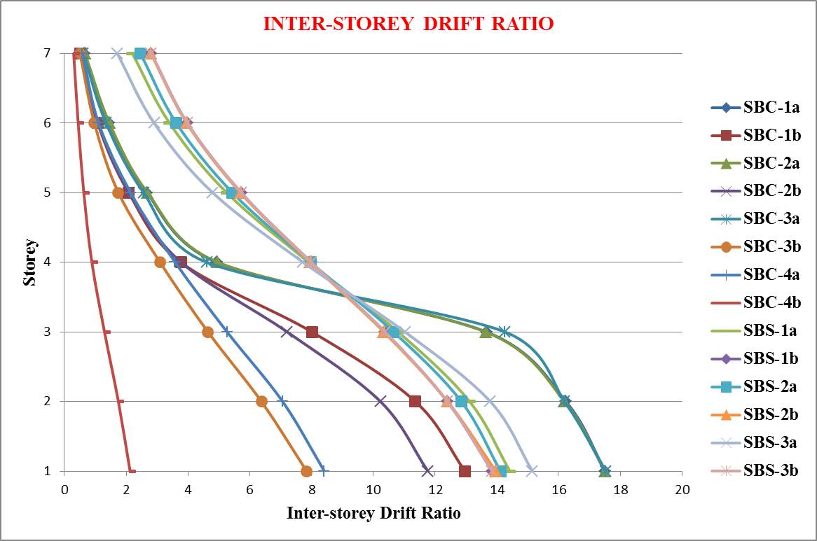
Fig. 7.7: Inter-storey Drift ratio after non-linear static pushover analysis

Fig. 7.8: Base reactions corresponding to the performance point, elastic limit and inelastic limit
Pushover curves of each model are obtained and the resulting demand-capacity curves of each building are shown in Appendix A-1. The base reactions corresponding to the performance point (i.e. the point at which capacity curve and demand curve intersects), elastic limit and inelastic limit is graphically plotted in figure 7.8. In demand-capacity curve, green colour curve shows the capacity curve and red colour curve shows demand curve. The structure has a good resistance if the demand curve intersects the capacity envelope near the elastic range as shown in Fig.3.2 (a). The structure will behave poorly during the imposed seismic excitation and need to be retrofitted to avoid future major damage or collapse if the demand curve intersects the capacity curve with little reserve of strength and deformation capacity as shown in Fig.3.2 (b). Depending on the weak zones that are obtained in the pushover analysis, we have to decide whether to do perform seismic retrofitting or rehabilitation. Appendix A-2 shows the plastic hinge formation of each model.
The following conclusions are obtained from the above results:
- SBC-1a, SBC-2a and SBC-3a models showed damage concentrations under non-linear static pushover analysis.
- SBC-1b, SBC-2b, SBC-3b, SBC-4a and SBC-4b models have low ductility and hence they failed before reaching the target displacement during monotonic pushover analysis.
- All SBC models have low ultimate load capacity when compared to SBS models.
- SBS-1b, SBS-2b and SBS-3b models have high reserve strength with 73.68 % increase in capacity. Among that SBS-1b model has 1.8 times high reserve strength in elastic range
- Capacity curves of all SBC models are similar in nature. They are initially linear but start to deviate from linearity as the beams and the columns undergo inelastic actions. When the buildings are pushed well into the inelastic range, the curves become non-linear with smaller slope and finally exhibited negative slope with sudden decrease in capacity.
- Capacity curves of all SBS models are similar in nature. They are initially linear but start to deviate from linearity as the beams and the columns undergo inelastic actions. When the buildings are pushed well into the inelastic range, the curves become linear again but with smaller slope. These models always exhibited positive slope with constantly increasing capacity suggesting good structural behaviour.
- All models passed performance criteria. From demand-capacity curve it is concluded that both the demand curve intersects the capacity curve well below the elastic limit. Therefore, it can be concluded that the margin safety against collapse is high and there are sufficient strength and displacement reserves.
- SBS-1b, SBS-2b and SBS-3b models have largest reserve strength and among theses, SBS-1b has highest reserve strength till elastic limit.
- Hinges are formed initially in braces then to beams then to columns with limited structural damage ensuring strong column-weak beam concept in all models.
7.3.3 Response Spectrum Analysis
Response spectrum analysis has been conducted on each model to know the maximum response of the system excited at its base by a time acceleration function. The response spectrum function definition has been adopted from International Building Code 2009 and is shown in figure 7.9. Eight modes were considered for the analysis and the modal load participation was around 98 percentages for all models. Mode shapes of SBC-1a are shown in Appendix A-3.
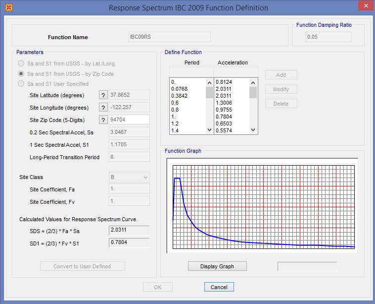
Fig. 7.9 Response Spectrum Function Definition (IBC 2009)
Inter storey drift ratio, Roof Drift and Base Reaction of each model have been shown in figure 7.10 through 7.12 respectively.
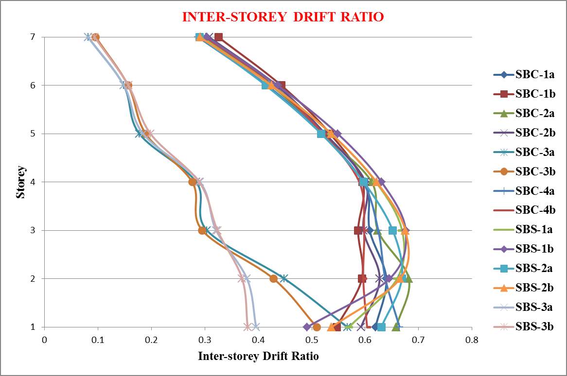
Fig. 7.10 Inter storey drift ratio after response spectrum analysis
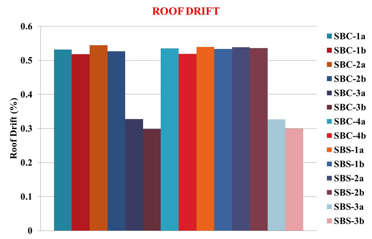
Fig. 7.11 Roof drift after response spectrum analysis
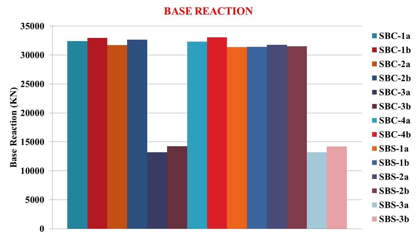
Fig. 7.12 Base Reaction after response spectrum analysis
The following conclusions are obtained from the above results:
- All models with dampers have better performance with an average of 57.64 % decrease in base reaction and 41.1 % decrease in roof drift.
- Among that, SPSW models have uniform inter-storey drift ratio
7.3.4 Linear Time History Analysis
Linear time history analysis has been conducted on each model using the periodic sine time history function as shown in figure 7.13. Two modes were considered for the analysis so as to get the modal load participation greater than 90 percentages for all models.
The displacement and base shear plots are shown in figure 7.14 and 7.17. From the results obtained, inter storey drift ratio, roof drift and base reaction have been graphically plotted and shown in figure 7.15, 7.16 and 7.18 respectively.
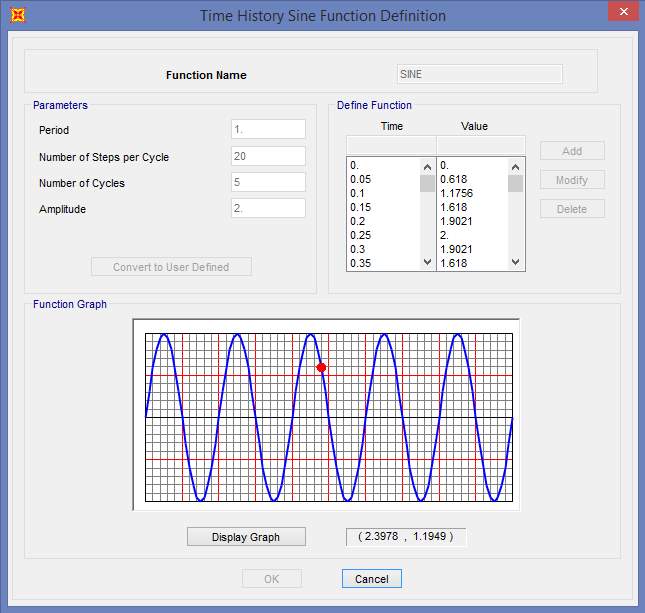
Fig. 7.13 Time History Function Definition (SINE Function)
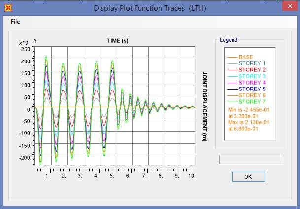
Fig. 7.14 Displacement Plot of SBC-1a
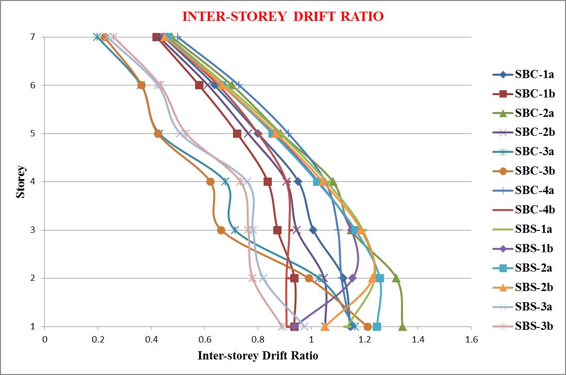
Fig. 7.15 Inter storey drift ratio after linear time history analysis
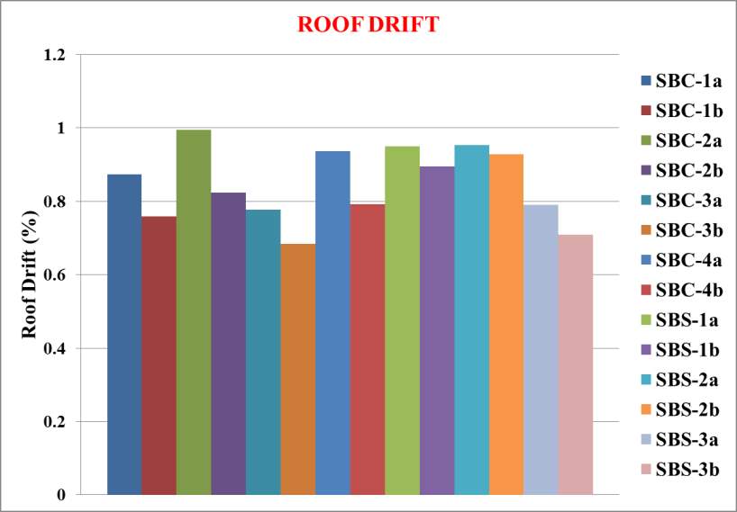
Fig. 7.16 Roof drift after linear time history analysis
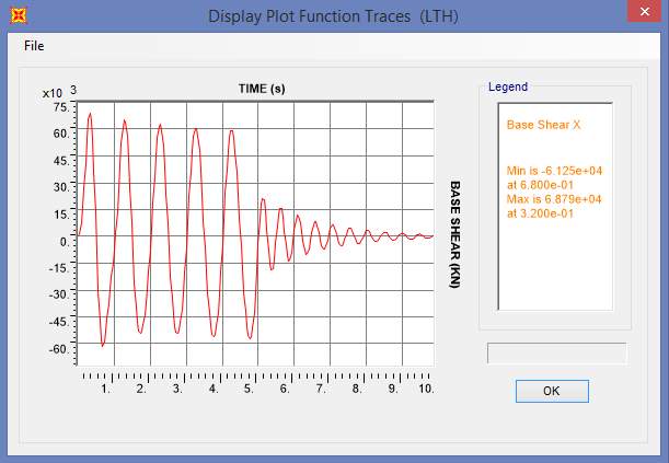
Fig. 7.17 Base Shear Plot of SBC-1a
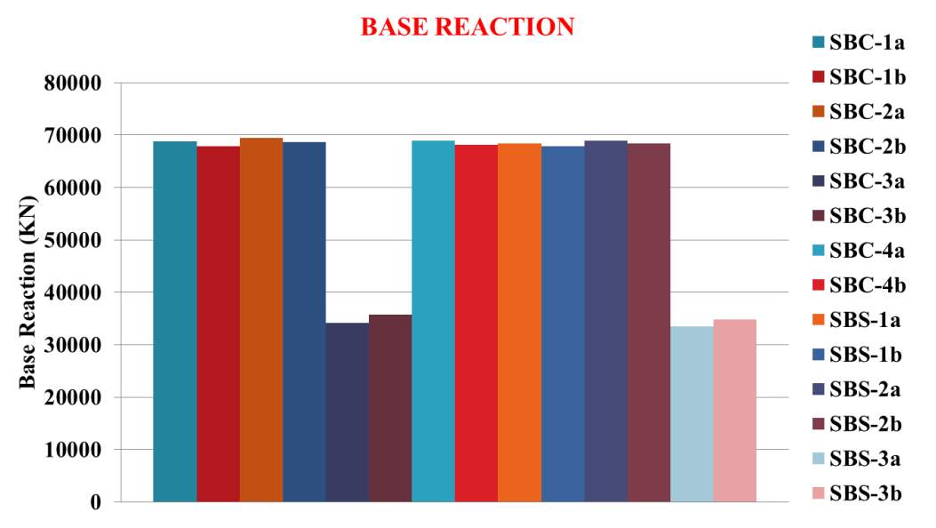
Fig. 7.18 Base reaction after linear time history analysis
The following conclusions are obtained from the above results:
- All models with dampers have better performance with an average of 49.74 % decrease in base reaction and 15.27 % decrease in roof drift
- Among that, SPSW models have uniform inter-storey drift ratio
7.3.5 Non-Linear Time History Analysis (FNA)
Non-linear time history analysis which is also known as Fast Non-linear Analysis (FNA) has been conducted on each model using the widely used time history function based on El Centro earthquake as shown in figure 7.19. Two modes were considered for the analysis so as to get the modal load participation greater than 90 percentages for all models.
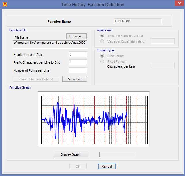
Fig. 7.19 Time History Function Definition (Elcentro)
The displacement and base shear plots are shown in figure 7.20 and 7.23. From the results obtained, inter storey drift ratio, roof drift and base reaction have been graphically plotted and shown in figure 7.21, 7.22 and 7.24 respectively.
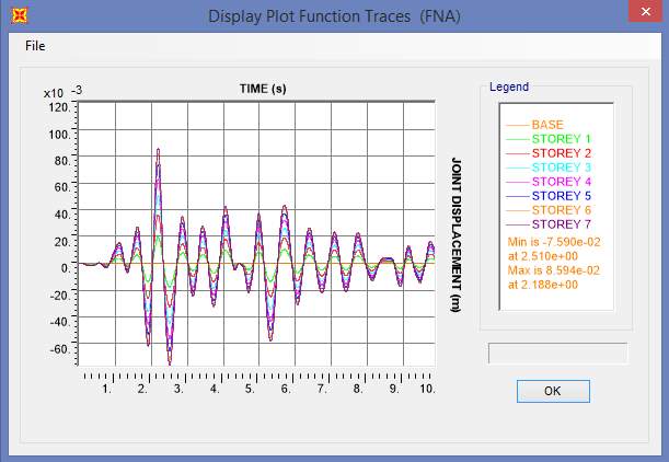
Fig. 7.20 Displacement Plot of SBC-1a
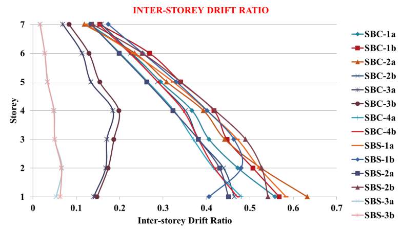
Fig. 7.21 Inter storey drift ratio after non-linear time history analysis
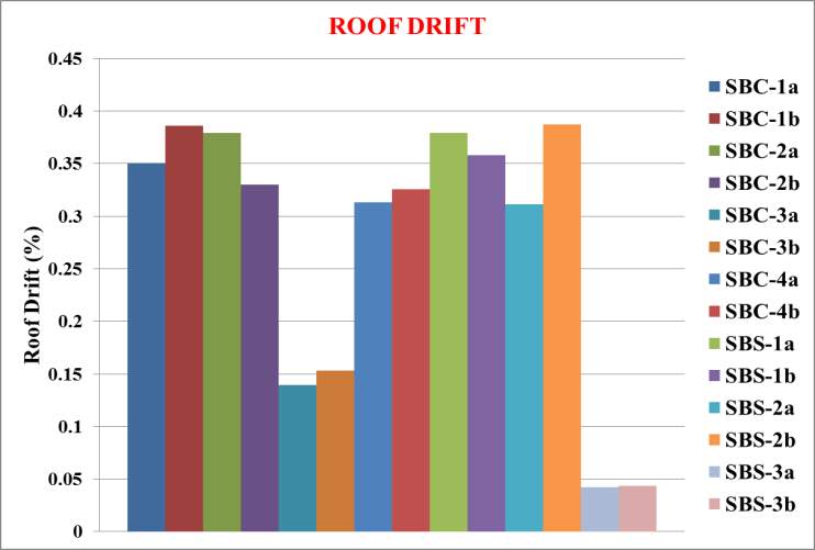
Fig. 7.22 Roof drift after non-linear time history analysis
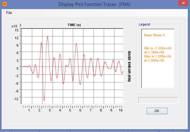
Fig. 7.23 Base Shear Plot of SBC-1a
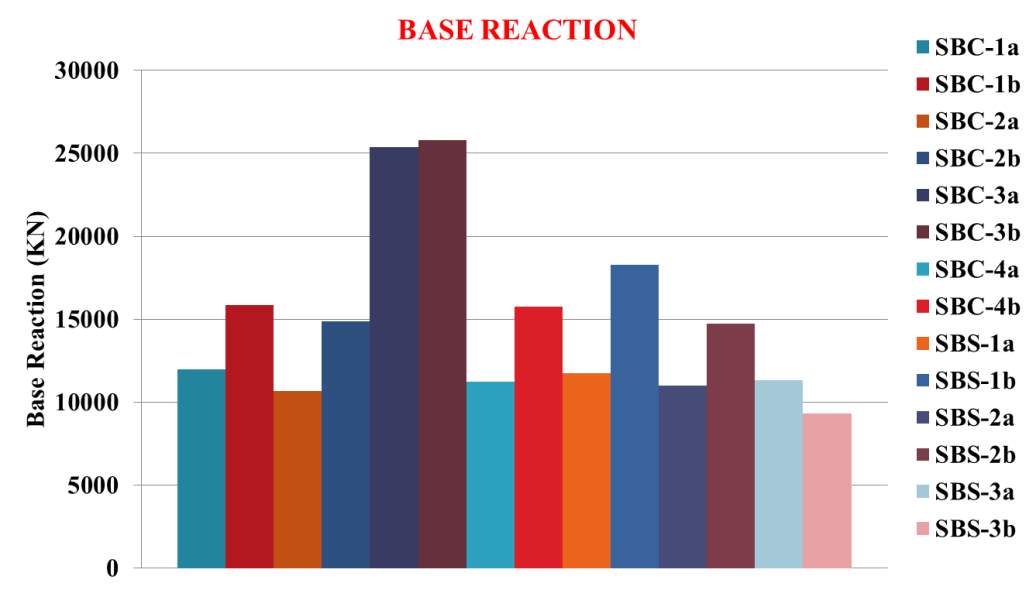
Fig. 7.24 Base reaction after non-linear time history analysis
The following conclusions are obtained from the above results:
- Models SBS-3a & SBS-3b have better performance
- Among that SBS-3b model was better in all results with 22.17% decrease in base reaction and 87.57% decrease in roof drift
CHAPTER 8: CONCLUSIONS
The primary objective of the project is to propose a better configuration of SBS which efficiently mitigates the damage concentration in steel braced frames. To achieve this primary objective, several secondary objectives are considered. Initially a literature study has been conducted regarding all possible conventional and innovative bracing systems including SBS’s. After that validation of SBS has been conducted with the values from appropriate literature. Then comparative study of different conventional bracing systems under linear static lateral load case has been done. Following that, concentric X braced frame along with new systems like Zipper frames and SBS are analysed under linear and non-linear static lateral load cases. Then studies on different configurations of SBS under linear/non-linear static and dynamic load cases are conducted and arrived at certain conclusions and recommendations as described in this section.
8.1 CONCLUSIONS
From first study, it is concluded that,
- X-CBF has better performance among conventional braced frame.
From second study, it is concluded that,
- Strong Back System effectively mitigated damage concentrations when compared to X-CBF & Zipper Frames.
From third study, it is concluded that,
- Under static loads, SPSW Strong Back models performed better, especially SBS-1b.
- Under dynamic loads, Strong Back models with dampers performed better, especially SBS-3b.
- Hence SBS-3b having good performance under static & dynamic loads is the most efficient Strong Back System in mitigating damage concentrations.
8.2 RECOMMENDATIONS
Strong Back System with damper devices, especially SBS-3b is recommended for severe dynamic load cases like high earthquake prone areas. For moderate seismic zone, Strong Back System with damping devices will be uneconomical. In such cases, steel plate shear wall models, especially SBS-1b will be suitable.
8.3 FUTURE SCOPE
Future scope of the work include cost analysis of each model so as to assess the economic feasibility of each model and also a study can be conducted on strong back system to optimise it structurally and economically to improve its efficiency.
Cite This Work
To export a reference to this article please select a referencing stye below:
Related Services
View all


Related Content
All TagsContent relating to: "Engineering"
Engineering is the application of scientific principles and mathematics to designing and building of structures, such as bridges or buildings, roads, machines etc. and includes a range of specialised fields.
Related Articles

DMCA / Removal Request
If you are the original writer of this dissertation and no longer wish to have your work published on the UKDiss.com website then please: