SDN Segment Routing Implementation
Info: 13047 words (52 pages) Dissertation
Published: 20th Feb 2025
Tagged: Computer Science
Abstract
Software Defined Networking (SDN) has become popular in the Network and ISP industry. It was first urbanized for the needs of data centre but now it’s widely used by Service Providers. Its major benefit is to minimize the complexity of the control panel in the MPLS design. Now in addition to SDN, segment routing came in the market to address the deficits of MPLS and it can be integrated in the SDN platform.
The motive of this case study is to utilize the concepts of segment routing and develop its full – stack implementation in the SDN environment. SDN platform based on OpenDaylight controller and a Mininet emulation environment for open flow switches configured on a two separate VMware stations.
At the back end, our implementation will compute the shortest path among all the switches and then push the corresponding flows to switches to support Segment Routing. The back-end implementation then accepts MPLS tunnel request from the front end to setup an optimum tunnel path between two hosts (or two sites) based on the available bandwidth constraint.
A front-end user interface, using HTML along with python Flask, is designed and implemented to co- operate with the back end to dynamically activate a tunnel between end hosts. The front end interface also allows the user to configure soft bandwidth upgrade or check the status of active connections.
Table of Contents
- Acknowledgements
- Abstract
- INTRODUCTION
- Software Defined Network:
- Segment Routing
- Global Segment Identifiers
- Local Segment Identifiers:
- Technical Background
- vCloud Director:
- OpenDay Light Controller:
- Apache Karaf:
- Open Flow:
- Rest APIs:
- Mininet:
- Wireshark:
- Python:
- Flask:
- Networkx:
- JSON:
- HTML:
- Design and Implementation
- Working Principle:
- Basic Design Groups and Components:
- 1. Initial database IDB
- 2. Back end:
- 3. Flow Generation:
- 4. Front end:
- ACTIVATE NEW CONNECTION:
- SOFT UPGRADE CONNECTION:
- Upgrade base pipe BW:
- Display active connections:
- Topology:
- RESULT AND ANALYSIS:
- ACTIVATE NEW CONNECTIONS:
- SAME SOURCE AND DESTINATION NODE:
- Display Active Connections:
- Flow Packet Capture Analysis: (Using Wireshark):
- Bandwidth Soft Upgrade:
- Base Pipe Bandwidth:
- Link Bandwidth Details:
- Core Details:
- Topology:
- CONCLUSION:
- REFERENCES:
- APPENDIX:
FIGURES & TABLES:
- Figure 1 SDN ARchitecture
- Figure 2 Basic Topology & RT Illustration
- Figure 3 Lab Setup on vcloud director
- Figure 4 ODL Architecture
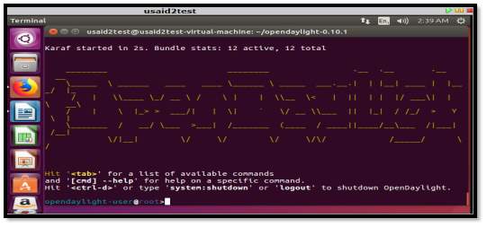
- Figure 5 ODL Karaf setup
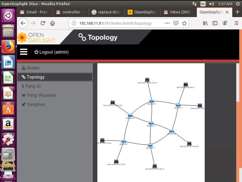
- Figure 6 ODL gui topology
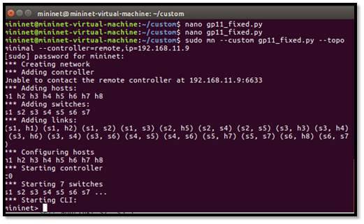
- Figure 7 mini net topology
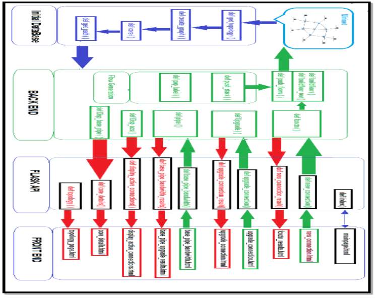
- Figure 8 PROJECT FLOW DESIGN
- Figure 9 ac_cntn.py
- Figure 10 jRT.py
- Figure 11 SRGB.py
- Figure 12 main_page.html
- Figure 13 Activate Connection
- Figure 14 Soft Upgrade Bandwidth
- Figure 15 Upgrade base-pipe bandwidth
- Figure 16 display_active_connections
- Figure 17 Core details after the initial execution of database
- Figure 18 def topology
INTRODUCTION
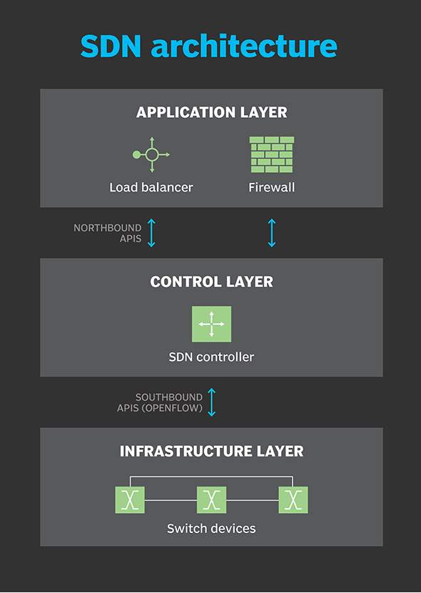
Software Defined Networking (SDN) is transforming the network architecture these days to a different level. In the Software Defined Network the control and data planes are decoupled, NI (network intelligence) and state are cogently centralized and the fundamental network infrastructure is abstracted from the applications. With all these high level implementation and integration, enterprise and carriers gain programmability, automation and network control with flexibility to adapt any change.
Segment Routing is a new technology that helps in dealing with MPLS issues maintaining the label switched data plane mechanism. Segment Routing is compatible with networking platforms that are based on control plane which makes it compatible for a SDN environment.
The objective of this case study is to design and implement a segment routing prototype in the SDN environment. The project embroils the full – stack implementation. At the back end our network design uses the shortest path with given bandwidth to direct the traffic over links. The back-end model is implemented on OpenDaylight controller (ODL). The controller is responsible to push the segment routing flows. Once the flows are installed the VM’s will handle the traffic based on the label stack carried by the discrete packet.
The secondary objective is to design a supporting feature which is the soft upgrade of tunnel bandwidth. To make it user friendly more features are added such as displaying core topology, routing and active connection implementation on click of a finger design on a HTML page. This enhance feature implementation is done to show that our project can be developed to support QoS and other similar software’s by adding a block of codes in our design. The Graphical User interface of front-end built in HTML webpage using python scripting also included for the simplicity of managing the design. It provides all the info on a single platform instead of going for different devices. The web portal can be available online to provide direct access to any user.
Software Defined Network:
Software-defined networking (SDN) focused on making a network flexible and less complex by having a centralized control and vacating the network nodes for data forwarding only. Its biggest advantage is to improve the network control for enterprise and service providers to rThe goal of SDN is to improve network control by enabling enterprises and service providers to respond as per business requirement.
In SDN, a network engineer or admin can design traffic flow from a centralized control console without touching switches in the network. The centralized SDN controller directs the switches to provide network services in regard to the connection between the servers. By doing so individual network devices make traffic decisions based on their routing table.
In a classic SDN scenario, a packet arrives at a network switch, and rules built into the switch's proprietary firmware tell the switch where to forward the packet. These packet-handling rules are sent to the switch from the centralized controller.
The switch -- also known as a data plane device -- queries the controller for guidance as needed, and it provides the controller with information about traffic it handles. The switch sends every packet going to the same destination along the same path and treats all the packets the exact same way.
Software-defined networking uses an operation mode that is sometimes called adaptive or dynamic, in which a switch issues a route request to a controller for a packet that does not have a specific route. This process is separate from adaptive routing, which issues route requests through routers and algorithms based on the network topology, not through a controller.
Segment Routing
Segment Routing aims to provide enhanced data packet forwarding without per-flow state maintenance within the network which reduces the complexity factor for both control and user planes. The packet forwarding is an alternative of source routing and it can be installed on top of pre-existing MPLS network.
Using SR the path of packet can be imposed through an orderly list of forwarding functions known as segments which consists of physical and logical element.
A Segment Identifiers are defined globally and should be renowned by all network nodes. Moreover, as the label is globally significant, an exposed SID may still reach the destination even when there is a node failure or error in programming.
Local Segment Identifier is defined locally within a node and the use of it by other nodes required the implementation of and categorical distribution mechanism. The segment identifiers can be used to implement custom policies to define and control flows in the network. This behavior with source-based routing relates well with the centralized functionality of controller in SDN and allows it to steer traffic through low latency path eliminating the need of additional protocol for traffic engineering
Figure 1.1 illustrates the concept of segment routing and how traffic is processed by the devices as it traverses along the path towards the destination. In segment routing, all the network nodes in the topology have the information to reach other network nodes and the corresponding labels to be processed. This is achieved with the use of global labels where each node is identified by a label from Segment Routing Global Block (SRGB).
Figure 1.1 shows the flow table entries that specify the shortest paths among the nodes. For example, the shortest path chosen from S1 to S7 is S1-S2-S5-S7.
Thus, when a packet from H1 to H4 enters the ingress node S1, and while S1 chooses the shortest path to forward this packet, it just needs to push label stack [16007] node labels stacked with host label i.e. [10004] to the predefined e-port # 1, where the e-port will direct the label stack to S2 without using any labels, S5 will use the next label to find its way to 16007 i.e. S7 where this label also get popped out and finally S7 will use the host label to identify and send the data to 10004 i.e. H5,respectively. Since the label entries associated with shortest path to S7 is pre-installed, the packet will follow the shortest path to S7.
In the case where there are more than one shortest paths available to the destination, we can traffic engineer the path selection or carry out the load balancing by distributing the traffic load among multiple available paths.
For example, if a packet from H2 to H3 enters the ingress node S1, and if S1 choose the path S1-S3-S6-S7 to forward this traffic, it would push the label stack [16006, 16007] to reach the final network node and the stack the host label i.e. [10003] to the data packet.
The labels 16006 and 10003 identify S6 and H3, respectively. The top label 16006 will direct the packet from S1 to S6 via S3. This represents first segment of the path. With the penultimate-hop-popping setup, S3 pops the label 16006. S6 will receive the packet with label stack [16007, 10003]. S6 subsequently pops the top label [16007] and forward the packet to S7. S7 in turn pop the last label (10003) and forward the traffic to H3.
For the tunnel between the source and destination by just pushing the appropriate label stack. Secondly, no addition flow entries are required to install to the flow tables of the intermediate nodes. The second characteristic is one of the major advantages of segment routing over traditional MPLS mechanism.
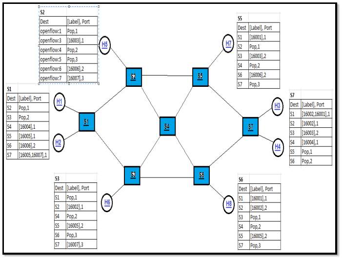
Figure 2 Basic Topology & RT Illustration
Technical Background
In this part of the report we will discuss the lab environment set up which we did for the case study. For implementing software defined network we used vCloud Director Platform where we have created two VMs to runOpenDay Light controller and mininet, respectively. The network topology which is monitored by controller is created by using Mininet on a separate VM which has a multiple Openflow Virtual Switches (OVS) running in it.
vCloud Director:
VMware vCloud Director is a platform that provides the ability to build secure, multi-tenant clouds by pooling virtual infrastructure resources into virtual datacenters and exposing them to users through Web-based portals and programmatic interfaces as a fully-automated, catalogue-based service.
The reason we prefer to use Comp Net vCloud services to create the lab environment for this case study is its remote and multiuser shared facility, which gives an ease to all the group members to work at our own schedules. Moreover the facility is fully secured with the disaster recovery (DR) provision which reinforce the stability of the system.
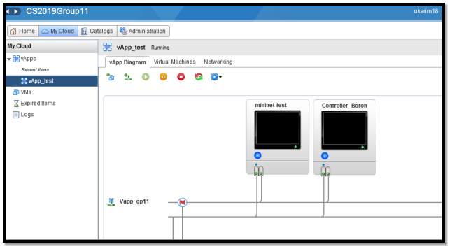
Figure 3 Lab Setup on vcloud director
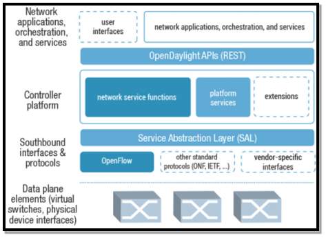
OpenDay Light Controller:
ODL is an Open source platform developed to provide support for SDN and NFV. There are so many SDN controllers, such as Ryu, Pox etc. OpenDaylight also supports OpenFlow, and also gives network solutions. It consists of Model-Driven Service Abstraction Layer (MD-SAL) at its core whose function is to represent the underlying network devices and applications as objects or models. It has a modular framework and supports multiprotocol. The features can be downloaded as per the user’s requirement.
Apache Karaf:
Apache Karaf is a small OSGi based runtime which provides a lightweight container onto which various components and applications can be deployed. It can be run as a standalone container and provides some enterprise-ready features like shell console, remote access, hot deployment, and dynamic configuration. Following are features that are required to run the controller desired services for mininet topology control using web interface.
feature: install odl-dlux-all odl-l2switch-switch-ui odl-openflowplugin-flow-services-ui odl-bgpcep-pcep odl-restconf-all
Open Flow:
OpenFlow (OF) is considered one of the first software-defined networking (SDN) standards. It originally defined the communication protocol in SDN environments that enables the SDN Controller to directly interact with the forwarding plane of network devices such as switches and routers, both physical and virtual (hypervisor-based), so it can better adapt to changing business requirements. It works as a southbound API that enables the communication between the controller (control plane) and the mininet topology (data plane).
Rest APIs:
Rest APIs are northbound APIs used for communication between network applications and controller. The applications can make HTTP calls using methods such as GET, POST, PUT and DELETE using restconf, which are based on POSTMAN application. REST API GET and PUT methods are used in the python code to get the topology information from ODL and also to make the ODL controller push the flows on the OVS devices.
Mininet:
It is used to emulate networking devices by creating virtual switches, hosts, and links on a single VM. It is based on standard Linux software. The networking devices support OpenFlow as it was created to support lab environment for SDN technology. The second VM in the project uses Mininet software to create the topology. It is possible to create custom topologies in Mininet using python script. Further information about Mininet can be found at the site. [V]
The python script is executed using the following command to create the custom topology.
sudo mn --custom topo.py --topo mytopo –mac --controller=remote, ip=192.168.11.9
Wireshark:
Wireshark is the widely known, freely available network protocol analyzer used to capture and analyze network traffic. It is installed and used on Mininet VM to capture the flows and ensure the correct implementation and functioning of devices as per the requirement. It can also be used for troubleshooting purposes in case the network behavior is different than expected.
Python:
It is an interpreted object oriented programming language which is widely used for network programmability due to its code readability and in-built library functions pertaining to network functionality. In this case study we have subjected all the necessary features performed by Opendaylight (ODL) controller through python scripting rather than using the built in features of ODL which has been written in Java scripts. This gives us the flexibility to induce our self-defined functions and add on features as per project requirement
Flask:
It is a micro framework written in python based on Jinja 2 template engine. It is used to develop the front-end of the project. The script develop for front-end reads user input, calls the back-end function as per the requirement and renders the result in the form of html pages stored in templates. Further details can be found on the site. [VI]
Networkx:
It is a python package for the creation, manipulation and study of the structure, dynamics, and functions of complex networks. [Definition source: [VII]]. The package is being used in the project to create a graph based on the topology information captured using REST API. Once the graph has been created, it is stored in .gml database for future retrievals and to calculate the shortest path between the end nodes.
JSON:
It is a JavaScript Object Notation specified by RFC 7159. It is used for encoding and decoding structured data. It is also used to transmit data over a network connection between client and server. In this project, it is being used for both of its functions to interpret the retrieved topology from mininet into python readable format information and to push the flows on OVS switches back in mininet from controller API. It is also being used to store the data structures which are defined to create and maintain an updated database as the new flows get installed on the OVS devices to avail communication between end hosts.
HTML:
HTML (Hyper Text Markup Language) is a markup language commonly used for creating webpages or websites. HTML is used in this project to create and design webpages for front-end development. These webpages are stored in the templates (folder) which are called by Jinja templates inculcated by Flask application in python scripting. Further information about HTML can be easily accessed from the site.
Design and Implementation
Working Principle:
SDN based segment routing works on the principle of shortest path flow using LDP, Each node in the network is defined with a globally unique identifier (i.e. labels) and the selected shortest paths from each source to destination are specified by the label(s) carried in the packet. However unlike conventional MPLS the labels would not be assigned directly to the nodes (switches and hosts) instead a SDN controller will generate the labels for each node (switches and hosts) and use them in the algorithm to define the shortest path to each destination node in the network. This makes the whole process of MPLS based tunnels faster and less consuming at switch end as the control plane has been decoupled and all the operations would be performed by the controller. Moreover, once the defined path has been installed on switches that path would not require to be computed again which will save a lot more time and increase the switch’s efficiency.
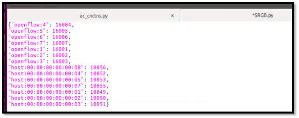
Another major advantage of having global labels is the assurance that the packet will reach the destination even when it might be diverted from the original path due to some network failures. However, the main goal of segment routing is to design and implement a stable topology where the traffic is source routed via a unique determined path.SDN based segment routing global labels start from 16000 for the network switch nodes. For hosts there’s no such convention however to keep the analogy in flow labels we choose to designate the host labels from 10000 and onwards.
Basic Design Groups and Components:
In order to execute the task in an organized manner we have distributed the design and implementation phase in three major sections, these sections define the flow structure of the project as well.
- Initial database IDB: The ultimate task of this section is to capture the basic case study topology from mininet. This task is achieved by creating a function which captures the topology using RESTConf API which is them converted in a format readable script using json.load(). Eventually this information is used in a function to perform the core job of calculating the shortest path for each node. All of these above information are saved in a database which will be handy to perform future tasks on the topology. The use of dictionaries compliments the project well as it is important to store the status of the connections and be able to retrieve them when required. The use of such database also helps to prevent an overlap or duplicity of information for different connections. Following are the four main functions of this section:
- Get_topology ( ): This method is defined to retrieve the basic topology information from mininet (information including but not limited to: # of hosts, # of switches, mac address) and convert in a format readable script using json.script () and store it in a variable.
- Create_graph( ): Once the topology has been captured it is passed through this function to create a graph by plotting nodes and edges and write the created graph in a .gml file. The graph then statistically calculates the shortest path against each node. This method also includes logic to assign labels and IDs for the nodes and hosts and also assign the egress ports for each node in shortest path direction and then write all the details in RT.py file in the form of a dictionary.
- Core ( ): It is another user defined method used to further elaborate the core details like assigning the pipe bandwidth and available bandwidth. It calls the get_path () method to calculate the shortest paths from each node to all other nodes and then assign corresponding label to generate the flows to be pushed on the OVS devices.
- Get_path ( ): This method is defined to read the graph stored in graph.gml file and then calculate the shortest path from the requested source to destination node. So, in order to call this method, we need to provide three parameters, source node, destination node and graph of the topology.
This section runs only once to create the initial database for the prototype and hence the name, IDB.
- Back end: The backend is the heart of the project that integrates all the information, storage, user input, builds and processes the flows and pushes them on OpenFlow Virtual Switches (OVS). Various methods are designed to implement different tasks. These methods also update the database and store them in respective files to ensure the maintenance of status of the network. The back end is further divided to accomplish 3 major tasks: Activate a new connection, soft upgrade the BW and upgrade the main pipe for all the links, Following are the four main functions of this section:
- build_flow ( ):This function works in the sequel of fcnctn() function, when a request is received from the front end to activate any connection, fcnctn( ) calls this function which then in return build the required flow for the requested source and destination nodes. This function works on three parameters [labels, flow id and index]. Once the flow is build it than call the push_stack ( ) and push_flow ( ) functions to finally load the instructions and parameters to controller.
- push_flow ( ):This method is defined to send the flow (instructions and information) to controller once ready using RESTConf API
- fcnctn ( ):This is one of the core functions of Backend .its main functionality is to receive the user input parameters from front-end for creating new connections. This function performs the necessary checks, limitations and errors before preceding the request to execution. This function also creates the database of all the active connections successfully passed to Mininet. It connects to Activate New Connection (.html) page using flask to get three user defined parameters i.e. (Source, Destination and Bandwidth). Figure xx shows the database created of activated connections :
- push_stack ( ):The job of this function is to create the xml format of information needs to pass on to the controller for flow generation.
- pop_label ( ):This function is created to pop the used labels from the stack this includes the labels at PHP routers as well
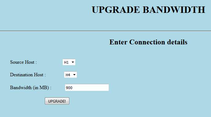
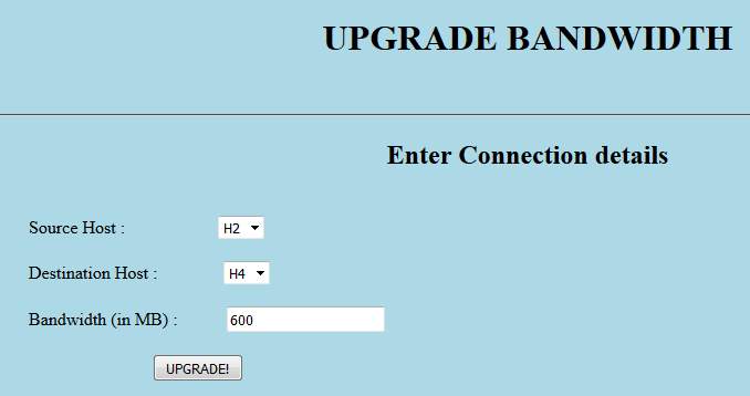
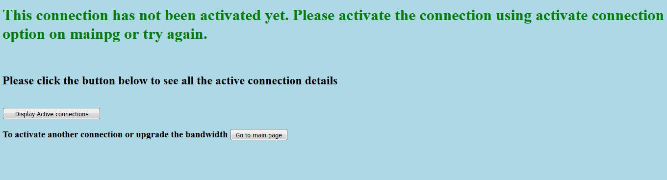
- Upgrade ( ): This function provides privilege to the user to set required Bandwidth on a certain established link connection. It receives the user defined parameters of (source, destination, Bandwidth) from front-end file “Upgrade Connection Bandwidth”(.html) using flask and upgrade the bandwidth of established connections, it also carry out the necessary pre-checks such as in case if the user has asked for asked for BW upgrade for any connection that has not been established yet it will return the massage :
"This connection has not been activated yet. Please activate the connection using activate connection option on main page or try again."
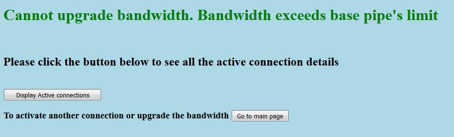
Or in case where user requested Bandwidth is beyond the available Bandwidth, it will return massage: “Cannot upgrade bandwidth. Bandwidth exceeds Available limit”.
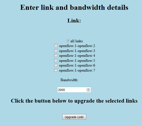
- Pipe ( ): This feature is provided to increase the base pipe bandwidth of any single or all the links together. As for default we have set the maximum of 1000mbs bandwidth limit on each link, In case if user wants to increase the bandwidth limit on any single link or all the links in the topology this function allows to dynamically accommodate users request., It receives from user the list of links where bandwidth needs to be upgraded and the new bandwidth that’s needs to be upgraded using front-end “Upgrade Base pipe BW” (.html) file through flak.
- Disp_acs ( ): This function has been created to share the active connections database with the user ,this database basically contains all the activated connections that has been created by user using “Activate New Connections” feature. This function converts the database file in format presentable to the user in readable format.
- Disp_base_pipe ( ): This function is used to display the core details to user at front-end. Basically it links the main database of backend with the front end where all the routing details including available links from host to host and other details are available. This information available in this database would be really crucial for decision making such as implementing traffic engineering. Figure xx shows the core database created :
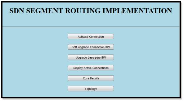
Frontend or user interface has been designed in .html format, Six major buttons have been created out of which three are to get user defined input parameters to run the relevant code and rest of the three to fetch and display the database and topology to user, respectively. All these featured buttons have been rendered to the user at the front page called as “mainpage.html”, which has been shown in the figure below:
def index(): Index is the function created to link up all featured functions at a single user page, this page is named as: “mainpage.html”.
Frontend has been structured using a user API method where Python flask is implemented to facilitate the communication between frontend user interface (.html) files with backend main python code. As described above, Flask is basically a micro web application framework that has been written in python which leverages the front end files to access the back end program for POSTing and getting data to the back end. It is implemented with the help of various created functions that has been written in flask to call and pass the parameters from frontend to backend and vice versa. Also some of the user defined error checks has been implemented in flask in order to avoid further computation burden over backend.
ACTIVATE NEW CONNECTION:
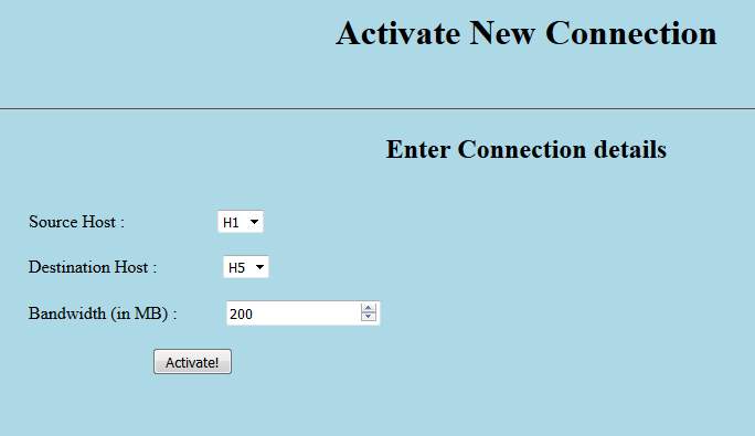
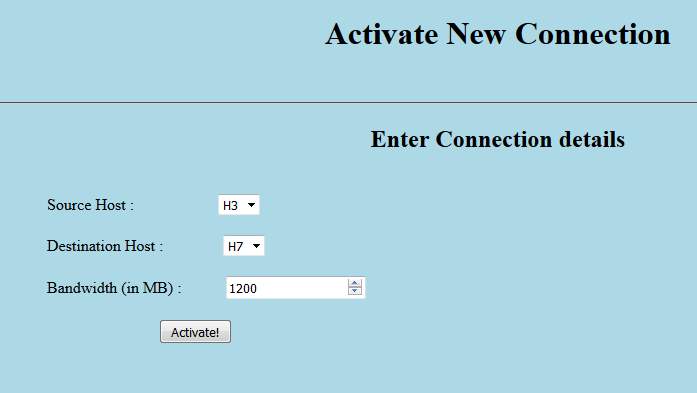
- def new_connection(): This function has been created to call the new .html page created to get the user input parameters for creating new connection, this new page is named as: “Activate New Connection” page.
- def new_connection_result(): This is the function which pass the data parameters obtained from user in previous function to the backend using POST function for further action. It calls the backend function in this function to pass the obtained values.
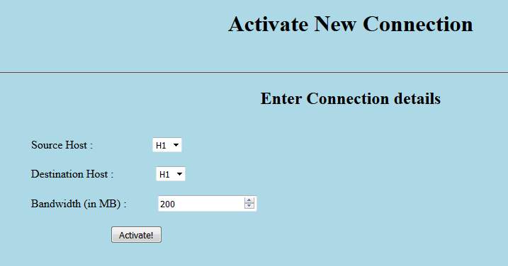
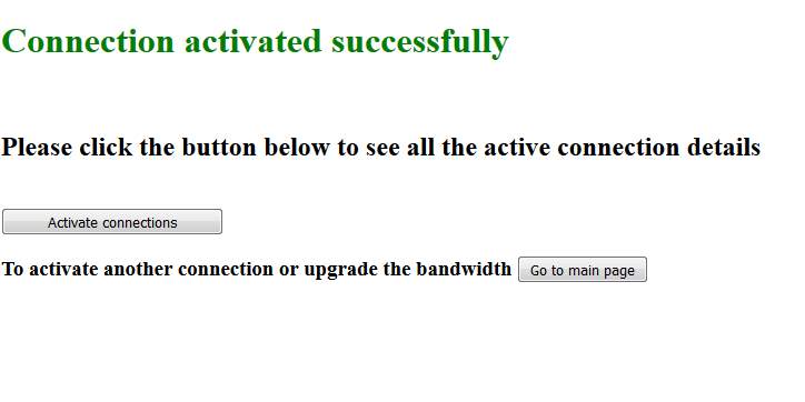
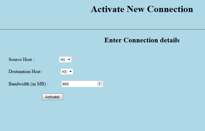
This page is obtained when user clicks “Activate Connection” button on the main page.
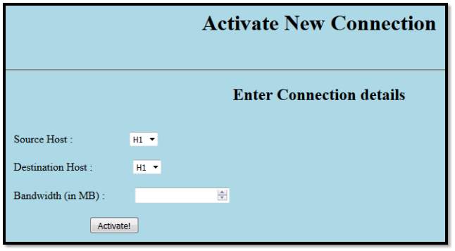
When user click “Activate Connection” button on the main page, the user is redirected to /new-connection. Here, new_connection function calls new-connection.html file that is the “Activate New Connection” page. This page sends the form data (Source Host, Destination Host and Bandwidth) to new_connection_result function as a HTTP Post request and the values from there are send to the backend function fcnctn(). Finally, it returns the information about connection success or connection error depending if the connection is successfully established or not, respectively.
SOFT UPGRADE CONNECTION:

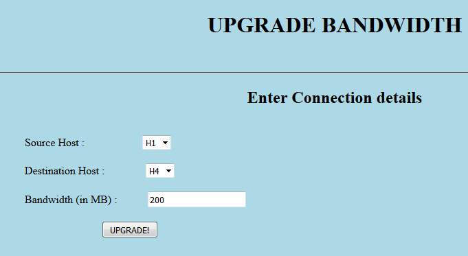
def upgrade_connection(): This function has been created to call the new .html page created to get the user input parameters for upgrading the bandwidth of already established connections, this new page is named as: “Upgrade Bandwidth” page.
def upgrade_connection_result(): This is the function which pass the data parameters obtained from user in previous function to the backend using POST function for further action. It calls the backend function in this function to pass the obtained values.
This page is obtained when user clicks “Soft upgrade Connection BW” button on the main page.
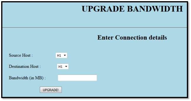
Figure 14 Soft Upgrade Bandwidth
On selecting this option on the main page, the user is redirected to python flask function “upgrade_connection ()”. This is the function from where upgrade_connection.html page is rendered. On clicking the UPGRADE! Button on this page, a POST request with entire form data is sent to python flask “upgrade_connection_result()” function. This function in return sends the values of [Source Host, Destination Host and Bandwidth] to the backend. The output of the bandwidth upgrade is retrieved from there and Jinja templates are used to dynamically render a HTML response based on the output.
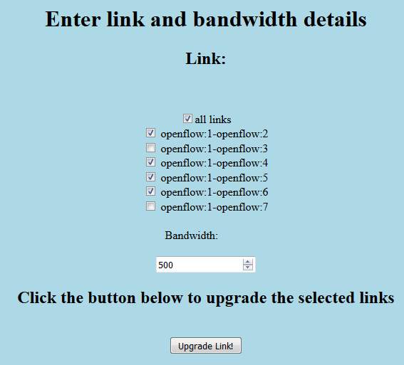
Upgrade base pipe BW:

def base_pipe_bandwidth(): This function has been created to call the new .html page created to get the user input parameters for upgrading the bandwidth of already established connections, this new page is named as: “Upgrade Bandwidth” page.
def base_pipe_bandwidth_results(): This is the function which pass the data parameters obtained from user in previous function to the backend using POST function for further action. It calls the backend function in this function to pass the obtained values.
This page is obtained when user clicks “Upgrade base pipe BW” button on the main page.
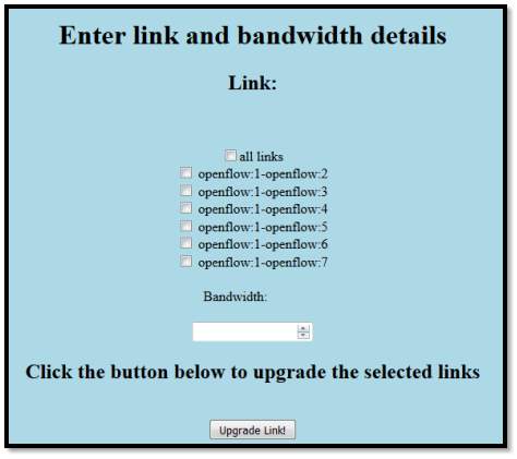
Figure 15 Upgrade base-pipe bandwidth
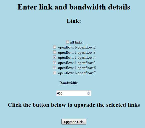
Further there is an option to upgrade the bandwidth for all the links and for the individual links. User can select either all links or a multiple of individual links, with an error message being displayed if all links is selected in combination with individual links. Again, Flask Jinga templates is used to render different responses or any error condition to the user. Here, base_pipe_bandwidth( () function is mapped to display the page as above from home page, with further base_pipe_bandwidth_results () function being used to display the results once upgrade link button as on above page is pressed. Further there is an option to upgrade the bandwidth for all the links and for the individual links.
Display active connections:

def display_active_connections(): This function renders the database file which keeps the track of all the active connections created by the user, once the connection has been created successfully it has been saved in the database.
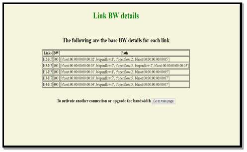
Figure 16 display_active_connections
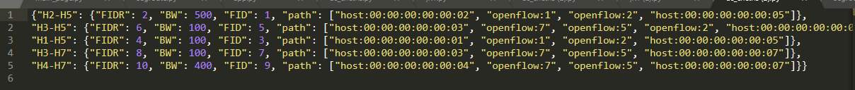
The fourth button on the main page is used to “Display Active connections” page. The page as shown above is routed through the /display-active-connections url mapped to a function of the same name in python flask application. The page displays the links (source host, destination host, bandwidth and path) of each of the active links as shown in the above screenshot. This information is requested by the python flask function from the backend functions (get_connection_topology.display_acs()). The provided data is then converted from Python data structures (dictionary) to an HTML table row by row. The table is then substituted into the HTML templates using Jinja and returned to the user.
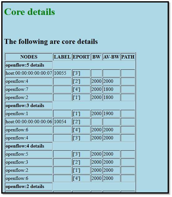
Core Details:

def core_details(): This Function has been created to link the main RT routing table database file with the user interface, This file has been created once by the backend when the topology is fetched and passed through the algorithm for shortest path calculation.
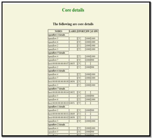
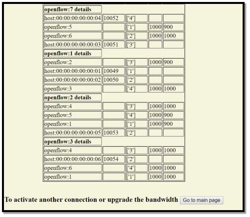
Figure 17 Core details after the initial execution of database
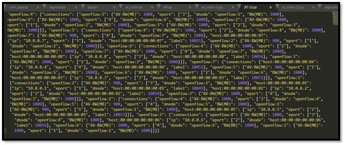
The fifth button on the main page is used to display routing table at every node. The page as shown above is routed through the (/core-details) url mapped to a function of the same name in python flask application. The page displays all the nodes in our topology, their neighbouring nodes and hosts, as well as bandwidth, available-bandwidth and eport for link to each of the neighbors as also shown in the above screenshot. This information is requested by the python flask function from the backend functions (get_connection_topology.disp_base_pipe()). The provided data is then converted from Python data structures (dictionary) to an HTML table row by row. The table is then substituted into the HTML templates using Jinja and returned to the user.
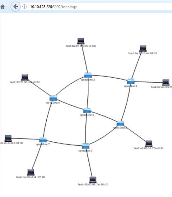
Topology:

def topology(): This function has been created to fetch the topology from ODL (Open Day Light ) Controller saved in .html format.

The last button is the topology button that shows the topology used in our project. This is rendered by calling topology () that renders the topology_page.html file and shows the topology.
RESULT AND ANALYSIS:
Once the design and implementation for all the objectives has been completed, we move forward to test and observe the results obtained.
1. The environment setup is tested to ensure the successful creation of required topology.
Core Details:
After the execution of topology, we move on to test the first section of the project. Once the script is executed, the initial database is generated, and core details can be checked on the frontend. Only the output for one node is displayed in the figure
ACTIVATE NEW CONNECTIONS:
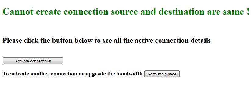
SAME SOURCE AND DESTINATION NODE:
|
USER INPUT PAGE |
|
|
|
OUTPUT |
|
|
DIFFERENT SOURCE AND DESTINATION NODE:
|
USER INPUT PAGE |
|
|
|
OUTPUT |
|
|

DIFFERENT SOURCE AND DESTINATION NODE (RECONNECTION):
|
USER INPUT PAGE |
|
|
|
OUTPUT |
|
|
Bandwidth beyond default limit:
|
USER INPUT PAGE |
|
|
|
OUTPUT |
|
|
Bandwidth exceeds available bandwidth limit:
|
USER INPUT PAGE |
|
|
|
OUTPUT |
|
|
Display Active Connections:
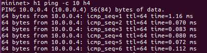
Ping Results on Mininet(testing Connectivity):
Flow Packet Capture Analysis: (Using Wireshark):
Table 1 icmp paket analysis for H2, H3 connection
|
In/out port |
Wireshark capture |
|
ICMP packet received on sw1 inport 1 |
|
|
SW1 pushes the labelstack for destination H4 and sends out its port towards SW2 from outport3 |
|
|
SW 2 receives the same packet from the SW1 at inport 1 |
|
|
Switch 2 pops the outer label and sends out its port 4 towards switch 5 |
|
|
Switch 5 receives the same packet from sw2 at inport 1 |
|
|
SW5 matches and pops the label and sends out at interface port 4 towards s7 |
|
|
SW7 in port 1 receives the packet from SW5 |
|
|
SW7 pops the bottom label and sends it out the port connected to H4. |
|
|
SW7 receives the return Traffic from host H3. |
|
|
SW7 matches the flow and pushes the label stack as per the flow actions and sends the packet out the port towards SW5 |
|
|
SW5 inport receives the packet from SW7 |
|
|
Switch 5 matches the top label and pops it before sending the packet to SW2 |
|
|
Switch 2 receives the packet from SW5 and performs the required match and pop actions |
|
|
SW1 receives the packet from SW2 |
|
|
Switch 1 pops the bottom of the stack label, sends it to H1, signifying successful reception of return traffic |
Table 1
Bandwidth Soft Upgrade:
Bandwidth Exceed Base Pipe Bandwidth Limit
:
|
User Input Page |
|
|
|
Output |
|
|
For the Connection that are not activated yet:
|
User Input Page |
|
|
|
Output |
|
|
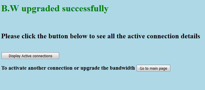
Bandwidth Upgrade Successfully:
|
User Input Page |
|
|
|
Output |
|
|
Base Pipe Bandwidth:
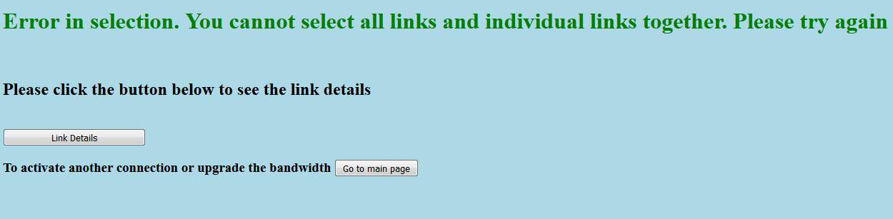
Error in selection of Base Pipe links:
|
User Input Page |
|
|
|
Output |
|
|
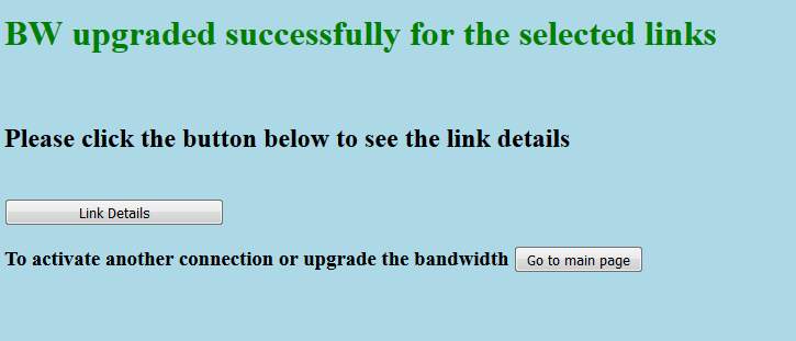
Base Pipe links Bandwith update successful (for all links) :
|
User Input Page |
|
|
|
Output |
|
|
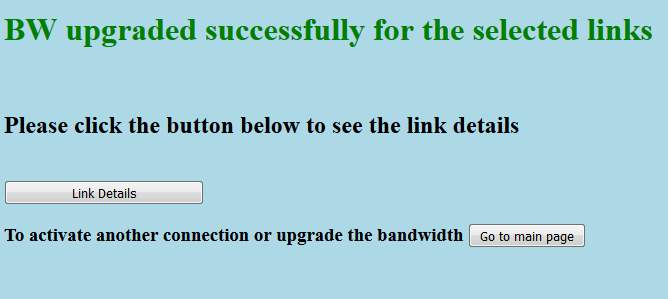
Base Pipe links Bandwith update successful (for selected links) :
|
User Input Page |
|
|
|
Output |
|
|
Link Bandwidth Details:
Core Details:
Topology:
CONCLUSION:
In this project we have achieved the goal of full stack implementation of Segment Routing using SDN in lab environment.
Our primary aimed at setting up the lab environment, scripting the topology in mininet, successfully interface mininet to ODL, retrieving the mininet topology in ODL, calculating the shortest path between all nodes, populating the database, activate connection on user input, dynamically implementing the MPLS tunnel, Apply traffic engineering based on max-min bandwidth concept, Create a user interface that can communicate with the backend in run time, do the necessary error checks before submitting the data back to backend code, connect the over all program database with frontend for user review, Push the flows back to mininet.
The implementation of these objectives has been achieved successfully.
The lab environment set up has been completed using Boron version of Open Daylight Controller (ODL) and mininet network emulator version 2.5.5.
The custom topology is created on the mininet using python scripting.
The backend and frontend implementation has also been carried out in python, because python has support for various numerous modules such as networkx which have in-built methods to calculate shortest paths and JSON that support the creation of graphs for the topology.
Flask API which is again micro framework in python is used to provide the patching services between frontend and backend, where Frontend has been implemented in HTML web pages to represent the featured services in GUI.
Database creation has also been one of the most crucial parts of the project which provides data archiving services at each level and made it available for user to review and decision making purposes.
Some Additional features has also been implemented successfully to further explore the application of basic code such as Active connections soft Bandwidth upgrade and base pipe bandwidth upgrade. These features provides traffic engineering in its own way while empowering user by ranging bandwidth of each and all links and even already established links as well.
However, there are several limitations within the project that could be taken care of in the future scope to enhance the features supported by the prototype designed.
The controller only supports the label stack up to 3 labels. So in a very large topology where more than 3 labels are required to define the flows this approach may create issues therefore an enhancement tot the current ODL controller would be one of the options or usage of any cast labels that identify cluster of nodes as one can be used.
Hence to this point, we can conclude that we have achieved the target of our project scope by setting up the SDN platform based on the opendaylight controller in a Mininet emulation environment, program the opendaylight controller to compute the shortest path and setup the MPLS tunnel Based on Segment Routing and setup a user interface so a tunnel can be
setup based on available bandwidth.
While we continued working for the implementation of need based source routing which is traffic engineering based on the concept of load sharing
REFERENCES:
I. https://tools.ietf.org/html/rfc7426
II. https://ieeeexplore.ieee.org/document/6386859.
III. https://www.openneteworking.org/wp-content/uploads/2014/10/openflow-spec-v1.4.0.pdf
IV. https://www.opennetworking.org/
V. https://github.com/mininet/mininet
VII. https://network.github.io
VIII. https://www.w3schools.com
IX. https://www.sdnxcentral.com
X. https://wiki.opendaylight.org/view/OpenDaylight_OpenFlow_Plugin:End_to_End_Flows
APPENDIX:
Backend:
def get_topology():
topo_url = "https://192.168.110.128:8181/restconf/operational/network-topology:networktopology/
topology/flow:1"
reply = requests.get(topo_url, auth=HTTPBasicAuth(usr, pwd))
rawd = reply.content
#print "This is raw data"
#pprint(rawd)
data = json.loads(reply.content)
print "\n Topology captured successfully \n"
#pprint (data)
return data
def create_graph(topo):
global nodes
global links
global eport
global SRGB
global hostid
global RT
global path
global host
nodes = topo['topology'][0]['node'] # Parsing All Nodes
links = topo['topology'][0]['link'] # Parsing All Links
SRGB = {}
RT = {}
host = {}
for node in nodes:
n = node['node-id']
if 'host' in n:
if node['host-tracker-service:addresses'][0]['mac'] in n:
ip = node['host-tracker-service:addresses'][0]['ip']
ID = ip[len(ip)-1]
mac = node['host-tracker-service:addresses'][0]['mac']
#print "mac",mac
#print "type",type(mac)
LID= mac[len(mac)-1]
#print "LID",LID
SRGB[n.encode('ascii', 'ignore')] = 10000+ int(LID)
host['H'+str(ID)] = n.encode('ascii', 'ignore')
host[n.encode('ascii', 'ignore')] = ip.encode('ascii', 'ignore')
#print ip
graph.add_node(n.encode('ascii', 'ignore'))#, node_id=hostid)
#print n
#pprint(host)
else:
s = ''
for i in n:
if i.isdigit():
s += i
label = 16000 + int(s)
graph.add_node(n.encode('ascii', 'ignore'))#, node_id=label)
SRGB[n.encode('ascii', 'ignore')] = label
RT[n.encode('ascii', 'ignore')] = {}
print "LABEL TABLE \n"
#pprint(SRGB)
#print "\n Routing table for all nodes till now \n"
#pprint(RT)
for i in RT:
RT[i]['connections'] = {}
for link in links:
snode = link['source']['source-node']
dnode = link['destination']['dest-node']
eport = link['link-id']
#print "eport",eport
global random_id
if 'host' in snode or 'host' in dnode:
graph.add_edge(snode, dnode)#, seg_id=random_id) #adding host-node edge
#following code is to get eport and add it in main RT
if 'host' in snode:
"""next"""
else: #getting eport
tmp = eport.find('/') #gives you the index of /
#print "tmp",tmp
ep = eport[(tmp-1)]
#print "ep",ep
for i in RT: #storing in RT
if i == snode:
RT[i]['connections'][dnode.encode('ascii', 'ignore')] = {}
RT[i]['connections'][dnode]['dnode'] = dnode.encode('ascii', 'ignore')
RT[i]['connections'][dnode]['ip'] = host[dnode]
RT[i]['connections'][dnode].setdefault('eport',[]).append(ep.encode('ascii', 'ignore'))
RT[i]['connections'][dnode]['label'] = SRGB[dnode]
#RT[i]['connections'][dnode]['BW(MB)'] = 1000
#random_id += 3
else:
graph.add_edge(snode, dnode)#, seg_id=random_id) # adding node-node edge
ep = eport[(len(eport)-1)] #getting eport
#storing in RT
for i in RT:
if i == snode:
RT[i]['connections'][dnode.encode('ascii', 'ignore')] = {}
RT[i]['connections'][dnode]['dnode'] = dnode.encode('ascii', 'ignore')
RT[i]['connections'][dnode].setdefault('eport',[]).append(ep.encode('ascii', 'ignore'))
RT[i]['connections'][dnode]['BW(MB)'] = 1000
RT[i]['connections'][dnode]['AV-BW(MB)'] = 1000
def core():
for i in RT:
src = i
#print "src:",src
for j in RT:
dst = j
#print "dst",dst
if src == dst:
"""next"""
else:
src_dst_path = get_path(src,dst)
#print "path: src:",src," dst:",dst," = ",src_dst_path
#print len(src_dst_path)
def get_path(source_node,dest_node):
path = list(nx.all_shortest_paths(graph, source=source_node, target=dest_node))
return path
def build_flow(path, flow_id,index):
SRGB = json.load(open("SRGB.py"))
RT = json.load(open("jRT.py"))
host = json.load(open("host.py"))
o = 18
#print path
l = len(path)
if len(path) == 4:
labelstack = [SRGB[path[l-1]]]
else:
labelstack = RT[path[1]]['connections'][path[l-2]]['label'][index]
labelstack.append(SRGB[path[l-1]])
#print labelstack
#print type(labelstack)
for i in labelstack:
#print i
ls = pld.labels(i,o)
o = o-2
#print labelstack
print "LS in main\n",ls
for i in range(1,l): # l, to make sure for goes till l-1 i.e. last router.
if i == 1 and l > 3: #label push on 1st node
#print "value of i this instance:",i
eport = RT[path[i]]['connections'][path[i+1]]['eport'][0]
#print "output port",eport
ip = host[path[l-1]]
#print "MATCH DST IP", ip
iport = RT[path[i]]['connections'][path[i-1]]['eport'][0] ## port cncted to
host is inport
#print "iport", iport
body = pld.push_stack(flow_id,iport,ls,eport,ip)
push_flow(path[i], flow_id, body)
elif i > 1 and i
#print "value of i this instance:",i
#print "THIS SHOULD NOT HAVE BEEN IMPLEMENTED FOR THE GIVEN TOPO"
iport = RT[path[i]]['connections'][path[i-1]]['eport'][0]
eport = RT[path[i]]['connections'][path[i+1]]['eport'][0]
#mlabel = SRGB[path[i+1]]
#print "flow_id,iport,eport,mlabel,bos",flow_id,iport,eport,mlabel,bos
body = pld.nopop_label(flow_id,iport,eport)
push_flow(path[i], flow_id, body)
elif i > 1 and i = l-len(labelstack)-1:
if i == l-2: # condition for php router, payload matches BOS and sets eth type to
0800 for boolean 1
bos = 1
print "PHP"
else:
bos = 0
print "non PHP"
iport = RT[path[i]]['connections'][path[i-1]]['eport'][0]
eport = RT[path[i]]['connections'][path[i+1]]['eport'][0]
mlabel = SRGB[path[i+1]]
#print "flow_id,iport,eport,mlabel,bos",flow_id,iport,eport,mlabel,bos
body = pld.pop_label(flow_id,iport,mlabel,eport,bos)
push_flow(path[i], flow_id, body)
return 1
def build_flow_rev(path,flow_id,index):
print "The Following is relate dto rev path\n"
new_path = list(reversed(path))
build_flow(new_path,flow_id,index)
return 1
def push_flow(node, flow_id, body):
flow_url = 'https://192.168.110.128:8181/restconf/config/opendaylightinventory:
nodes/node/'+node+'/table/0/flow/'+str(flow_id)
#print flow_url
headers = {'Content-Type': 'application/xml','accept': 'application/xml'}
#print headers
responseData = requests.put(flow_url, data=body, headers=headers,
auth=HTTPBasicAuth('admin', 'admin'))
pprint(responseData)
abc = responseData.content
#print "\nnode",node
pprint (abc)
def fcnctn(src,dst,BW):
global flow_id
ac = json.load(open("ac_cnctns.py"))
uRT = json.load(open("jRT.py"))
host = json.load(open("host.py"))
srcn = host[src]
dstn = host[dst]
sd = str(src)+'-'+str(dst)
rsd = str(dst)+'-'+str(src)
paths = get_path(srcn,dstn)
slct_path = []
slct_BW = []
#global pno
BW = int(BW)
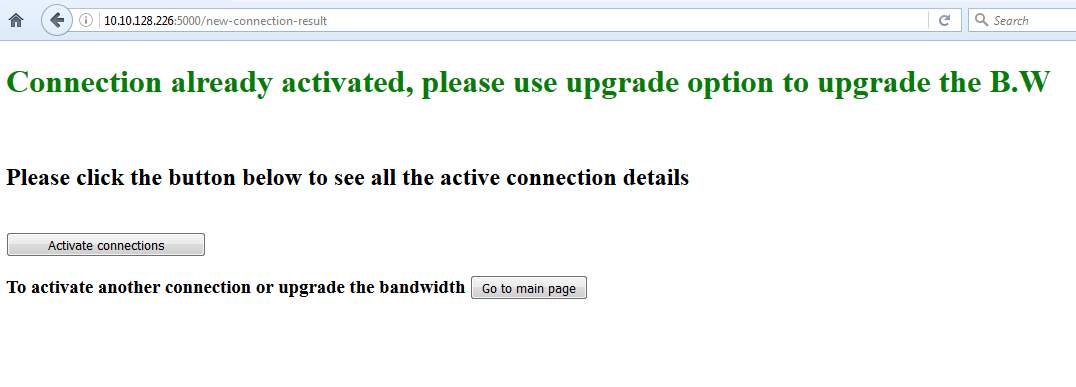
if sd in ac or rsd in ac:
print "Already activated"
return "Connection already activated, please use upgrade option to upgrade the B.W"
elif len(paths[0]) == 3:
return "Hosts on same switch"
else:
"""next"""
for i in paths: # This for loop is for TE concept of max-min BW
AvB = []
a = 0
p = i[1:-1]
for j in range(0,len(p)-1):
if BW
#print "BW OK for ", p[j], p[j+1]
AvB.append(uRT[p[j]]['connections'][p[j+1]]['AV-BW(MB)'])
else:
#print "AV-BW", uRT[p[j]]['connections'][p[j+1]]['AV-BW(MB)']
a += 1
#print "a...",a
if a == 0:
slct_path.append(i)
slct_BW.append(min(AvB))
#print "I",i
else:
"""next"""
if slct_path==[]:
#print "no path"
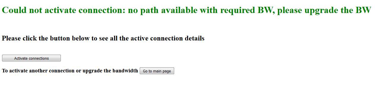
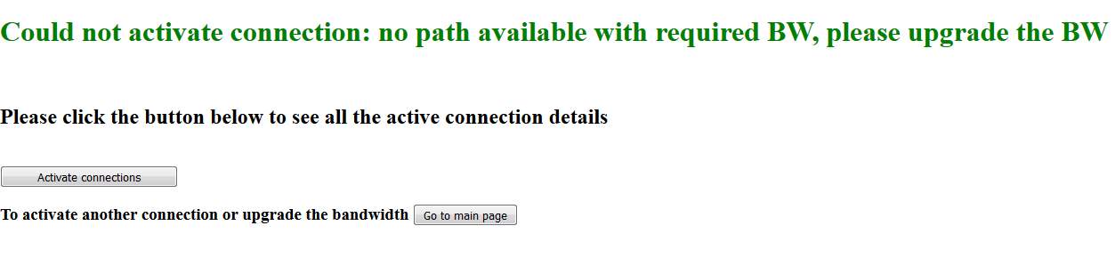
return "Could not activate connection: no path available with required BW, please
upgrade the BW"
else:
mAvB = max(slct_BW)
path = slct_path[slct_BW.index(mAvB)]
if len(ac) == 0:
ac[sd] = {}
fid =0
ac[sd]['FID'] = fid+1
ac[sd]['FIDR'] = fid+2
else:
ac[sd] = {}
ac[sd]['FIDR'] = 0
fid = max(ac, key = lambda x: ac[x]['FIDR'])
ac[sd]['FID'] = ac[fid]['FIDR']+1
ac[sd]['FIDR'] = ac[fid]['FIDR']+2
ac[sd]['path'] = path
ac[sd]['BW'] = BW
flow_id = ac[sd]['FID']
pprint(ac)
index = paths.index(path)
#labelstack = RT[path[1]]['connections'][path[len(path)-2]]['label'][index]
print "index",index
#print "ls", labelstack
for k in range(1,len(path)-2): #this section is to subtract the activated
connections B.W from AV-BW and update it in the database
print "printing...", uRT[path[k]]['connections'][path[k+1]]['AV-BW(MB)']
uRT[path[k]]['connections'][path[k+1]]['AV-BW(MB)'] -= BW
uRT[path[len(path)-1-k]]['connections'][path[len(path)-1-k-1]]['AV-BW(MB)'] -= BW
flag = build_flow(path, flow_id,index)
flow_id += flow_id
flag = build_flow_rev(path, flow_id,index)
print "FLAG", flag
if flag == 1:
with open("jRT.py", "wb") as f:
f.write(json.dumps(uRT).encode("utf-8"))
with open("ac_cnctns.py", "wb") as f:
f.write(json.dumps(ac).encode("utf-8"))
print "SUCCESS"
return "Connection activated successfully"
else:
return "Oops something went wrong.. Please try again."
#pprint(uRT)
#print slct_path
def upgrade(src,dst,BW): #Decide if you wanna assign BW to hosts in RT and also upgrade it
accordingly in this function
uRT = json.load(open("jRT.py"))
ac = json.load(open("ac_cnctns.py"))
#pprint(uRT)
flag = 0
sd = src+'-'+dst
if sd not in ac:
return "This connection has not been activated yet. Please activate the connection
using activate connection option on mainpg or try again."
else:
BW= int(BW)
path = ac[sd]['path']
cBW = BW - ac[sd]['BW']
for i in range(1,len(path)-2):
print i
if uRT[path[i]]['connections'][path[i+1]]['AV-BW(MB)'] - cBW > 0:
"""next"""
else:
flag += 1
if flag == 0:
for i in range(1,len(path)-2):
uRT[path[i]]['connections'][path[i+1]]['AV-BW(MB)'] -= cBW
uRT[path[i+1]]['connections'][path[i]]['AV-BW(MB)'] -= cBW
ac[sd]['BW'] = BW
with open("jRT.py", "wb") as f:
f.write(json.dumps(uRT).encode("utf-8"))
with open("ac_cnctns.py", "wb") as f:
f.write(json.dumps(ac).encode("utf-8"))
return "B.W upgraded successfully"
else:
return "Cannot upgrade bandwidth. Bandwidth exceeds base pipe's limit"
def pipe(links,BW):
uRT = json.load(open("jRT.py"))
BW = int(BW)
if links[0] == 'all links' and len(links) > 1:
return "Error in selection. You cannot select all links and individual links
together. Please try again"
elif links[0] == 'all links':
for i in uRT:
for j in uRT[i]['connections']:
if 'BW(MB)' in uRT[i]['connections'][j]:
oBW = uRT[i]['connections'][j]['BW(MB)']
uRT[i]['connections'][j]['BW(MB)'] = BW
uRT[i]['connections'][j]['AV-BW(MB)'] += (BW-oBW)
else:
for k in links:
for i in uRT:
for j in uRT[i]['connections']:
if i in k and j in k:
oBW = uRT[i]['connections'][j]['BW(MB)']
uRT[i]['connections'][j]['BW(MB)'] = BW
uRT[j]['connections'][i]['BW(MB)'] = BW
uRT[i]['connections'][j]['AV-BW(MB)'] += (BW-oBW)
uRT[j]['connections'][i]['AV-BW(MB)'] += (BW-oBW)
with open("jRT.py", "wb") as f:
f.write(json.dumps(uRT).encode("utf-8"))
return "BW upgraded successfully for the selected links"
def disp_acs():
ac = json.load(open("ac_cnctns.py"))
if bool(ac) == True:
for i in ac:
path = ac[i]['path']
for j in range(0,len(path)):
path[j] = path[j].encode('ascii','ignore')
ac[i]['path'] = path
return ac
def disp_base_pipe():
bp = {}
RT = json.load(open("jRT.py"))
for i in RT:
for j in RT:
if i
bp[i.encode('ascii','ignore') + '-' + j.encode('ascii','ignore')] = {}
bp[i.encode('ascii','ignore') + '-' + j.encode('ascii','ignore')]['BW'] =
RT[i]['connections'][j]['BW(MB)']
bp[i.encode('ascii','ignore') + '-' + j.encode('ascii','ignore')]['AV-BW'] =
RT[i]['connections'][j]['AV-BW(MB)']
return bp
Flow generation:
def push_stack(flow_id,iport,ls,eport,ip):
a = '
xmlns="urn:opendaylight:flow:inventory">
ls1 = '
'
0
payload = a + ls + ls1
print "payload built for installing:\n",payload
return payload
def pop_label(flow_id,iport,mlabel,eport,bos):
a = '
xmlns="urn:opendaylight:flow:inventory">
action>
b = '
str(eport)+'
'
c ='
priority>300
if bos == 1: # condition for PHP router
eth = '2048'
bos = '
payload = a + '2048' + b + '
else:
eth = '34887'
payload = a + '34887' + b + '
print "payload built for installing:\n",payload
return payload
def nopop_label(flow_id,iport,eport):
payload = '
xmlns="urn:opendaylight:flow:inventory">
action>
print "payload built for installing:\n",payload
return payload
def r_lookup(flow_id,ip,eport):
payload = '
xmlns="urn:opendaylight:flow:inventory">
str(eport)+'
'
ipv4-destination>' + ip+'/32
0
#print "payload built for installing:\n",payload
return payload
Cite This Work
To export a reference to this article please select a referencing stye below:
Related Services
View all


Related Content
All TagsContent relating to: "Computer Science"
Computer science is the study of computer systems, computing technologies, data, data structures and algorithms. Computer science provides essential skills and knowledge for a wide range of computing and computer-related professions.
Related Articles

DMCA / Removal Request
If you are the original writer of this dissertation and no longer wish to have your work published on the UKDiss.com website then please: