New Advances in Site Investigations and In-Situ Testing and Monitoring
Info: 9034 words (36 pages) Dissertation
Published: 5th Jan 2022
Tagged: ConstructionEngineering
Executive Summary
As for the engineering purposes of construction projects, the quality of soil has a great influence on the structure and the soil investigation before the start of project is also a crucial process as a civil engineer. In order to determine the quality of the soil, the investigation process has to be done prior to construction process. Among many site investigation methods, the in-situ testing and monitoring of the soil has been the most suitable methods chose by many civil engineers. Many different types of methods are included in the in-situ testing of the soil and the most commonly used methods are Cone Penetration Test (CPT) method, Standard Penetration Test (SPT) method and the Flat Plate Dilatometer Test (DMT) methods are mostly used and they are mainly based on the logging tests.
Nowadays, most geo-mechanical engineers use CPT method since it is the most reliable and effective method. Moreover, it can produce the result data in the short period of time and more importantly, it is a cost saving method as well. However, there are others useful and reliable methods also existed such as Pressure Meter Test (PMT) method, Vane Test method and Screw Plate Load Test (SPLT) method. All these methods are used to determine the quality of the soil and soil parameters. According to Craig (1996), some geologists tried to combine the logging-based tests with other tests and introduced many test methods such as seismic CPT and the cone pressure meter. In this paper, the knowledge of soil investigation and the different methods of in-situ testing will be discussed and described while showing some comparisons between these methods for the help of future research papers.
Introduction
The common problem faced in geotechnical engineering is uncertainties which mainly includes measurement error, natural variabilities and transforming uncertainties. In order to reduce the risk of these uncertainties, a proper soil investigation has to be done at site before the project starts particularly in soil parameters (Ching & Phoon 2012). One of the best approaches to do the site investigation is the in-situ testing method.
The in-situ testing of the soil can be done by placing the instrument at a precise point in a borehole and then test the characteristics of in-situ soil or rock (Cruz 2013). The in-situ site investigation of specific soil has a great effect regarding the type of soil, site and quality of structure. In some projects, the accurate data from in-situ tests is required whereas the approximate data is sufficient for project planning. Today, there are many options to do in-situ soil test. Some of the commonly used tests are Standard Penetration Test (SPT), Cone Penetration Test (CPT), Field Vane Test, Plate Load Test and Dilatometer Test.
In this research paper, these test methods are going to be taken and explain a brief description about the methods. In geotechnical investigation, there are mainly two types of investigation existed; surface investigation which is more simple and easier that the description from the site in sufficient whereas the subsurface investigation is more complicated as it based on the lab test.
Background of the Study
The information about how geotechnical investigations were done in the past is also essential as it can highlight the mistakes that were done in previous investigations and lead to the correct way for future investigations. Moreover, doing background research regarding the geotechnical investigations would also provide safe and economical design for the project and the site engineer can expect the possible uncertainties and conditions that he or she may encounter. Adeoti et al. 2016 described the surface investigation processes which includes the in-situ site survey and one-dimensional information of the subsurface condition. In the early stages of surface investigation, a reconnaissance geotechnical survey has to be done to get the required two-dimensional and three-dimensional data. After that stage, the subsurface can be investigated by drilling process (Adeoti et al. 2016).
For many years, the art of geotechnical investigations had been based on the past experience and experiments without any scientific facts or knowledge. One of the well-known examples that relates to soil bearing capacity before 18th Century is the Leaning tower of Pisa as shown in Figure 3.1, located in Italy. The tower used to tilt in the east, north, west and south in last. According to the previous investigations, the main reason behind the problem is that a weak clay layer lied under the ground surface which caused the tower to tilt (Das & Sobhan, 2014).

Figure 3.1 Leaning tower of Pisa, Italy
In the late 17th century, the first and most reliable method to determine the lateral earth pressure was found by Charles Coulomb particularly military rampart. Charles Coulomb also determined the maximum shear stress on the slip plane and if necessary, Coulombs’ two-dimensional stress state theory can be combined with Christian Otto Mohr’s which becomes Mohr-Coulomb theory.
After 1900, a Swedish chemist and soil scientist, Albert Mauritz Atterberg founded clay-size frictions according to the percentage of particles’ weight. He highlighted the importance of clay particles and thus, defined the plasticity index with the difference between plastic limit and liquid limit (Das & Sobhan, 2014). Later in the 19th century, Henry Darcy introduced the coefficient of permeability of soil which acts as a useful tool in geotechnical engineering till nowadays.
For the modern geomechanics era, Karl Terzaghi is known as the father of modern soil mechanics who brought a variety of useful theories for soil mechanics which are useful till nowadays. He introduced many theories and methods regarding the effective stress and proved that shear strength of soil has a great influence on the effective stress. Moreover, he brought theories to define the bearing capacity of foundations and rate of settlement in clay regarding the consolidation.
In modern soil mechanics technology, the site investigation procedures are mostly related to the in-situ testing, site survey, sample collection and several lab tests in determining the quality of soil and site behavior. The in-situ site investigation has been a commonly used method in many projects and among several in-situ investigation methods, Cone Penetration Test (CPT) method and Standard Penetration Test (SPT) method are the most commonly used.
Objectives of the Study
The primary objective of a Geotechnical site investigation is to determine the ground conditions of the proposed site and quantify all possible risks posed to the development and construction of the structure or building. Hence, to attain feasibility of the goal, the following sub-goals were formulated:
- To be able to assess the f the site and perform cost-effectiveness analysis for the proposed design.
- To forecast any probable changes that can happen in the soil and the surrounding circumstances.
- To provide engineering properties of the soil, characteristics of the soil layers, and the position of the groundwater,
- To predict the bedrock position and verify the depth of the overburden soil.
- To locate the groundwater level and possible corrosive effect of soil and water on foundation material.
Scope of the Study
There are several scopes of the geotechnical site investigation, and it generally starts at the planning stage and adjusted with time to time. The scope of the investigation is as follows:
- Collection of information such as maps related to the project site, public services, and nearby structures.
- Make preliminary site investigation to collect site and ground properties concerning the project site
- Borehole drilling and sampling of disturbed and undisturbed samples
- Perform necessary field and laboratory tests for soil property identification
- Formulate the Geotechnical Site Investigation Report
- Apply engineering analysis and evaluation of field findings and results to the conceptual design
Stages of Geotechnical Site Investigations
The unforeseen ground conditions can profoundly impact the success of a construction project; thus, the need for a geotechnical site investigation arises. In general, site investigation can be divided into basic approaches, surface and sub-surface as shown in Figure 6.1.1. The tree is most commonly used for planning of the development of the site and to help its three main ingredients (staff, equipment, and techniques) to balance out. It is the process wherein its gathers all information concerning the site of the proposed structure design and its surrounding area. The primary purpose of conducting site investigation is that it can help recognise the suitability of the site for construction and to avoid unnecessary expenses in the design development. It can be divided into three main stages of investigation namely: Desk Study, Site Investigation, and Intrusive Ground Investigation.
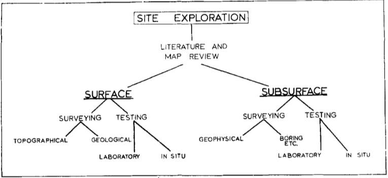
Figure 6.1. Site Investigation Organisational Tree (Fookes, 1967)
Desk Study
In the construction industry, desk studies are known but often under-used method for gathering and assessing existing information about the site. It collates and review all existing information available about the site and is carried out at an early stage of site appraisal; therefore, helps in the assessment of the feasibility of the study and if it can continue to stage II which is site investigation (Fookes, 1967). The primary objective of conducting a desk study is to provide detailed information about the existing ground conditions (Simons et al.,2002). Various techniques can be used to execute this stage to keep the costs at its minimum and save the rest for the other stages; the following as shown in Figure 6.1.2. are the typical materials that can be used:
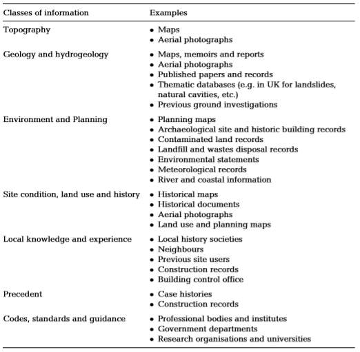
Figure 6.2. Information for Geotechnical Desk Studies (Shilston et al., 1998)
The information gathered is used to identify likely geotechnical hazards to the proposed design of the structure (Briaud, 2013). Furthermore, it is helpful to draft a preliminary desk study report before carrying out the walk-over survey or site investigation. It should include all the interpretation of all the data gathered. Also, a plan of the proposed exploratory hole location suggested methods and sampling frequency, in-situ and laboratory testing details, and all other necessary non-intrusive investigation works should be clearly stated in the report (Clayton and Smith, 2013). Hence, the information collected can also help in designing more economical and risk-free foundations and geotechnical structures.
Site Investigation
Following the initial investigation of the site from existing reports and doing photo mapping, a walk-over survey is conducted which includes a physical examination of the landform, drainage, and behaviour of the soil. In this stage, a systematic review of the site is performed wherein the behaviour of the adjacent structures is observed. Also, visible cracks and noticeable sags are considered because it may influence the design of the proposed building or structure (Fookes, 1967). It typically provides valuable information on the following matters (Simons et al.,2002; Clayton and Smith, 2013):
- Topography – includes signs of slope instability, poorly drained hill slopes, and signs of ground settlement.
- Geology – exposures of rock and soil which should be sampled and examined for to check its properties and characteristics
- Surface water and groundwater –signs of flooding and evidence of a high groundwater table
- Vegetation – signs of vegetation to check if the ground has evidence of contamination like bare patches of ground, staining, and leachate
- Structures – existing development projects and remnant foundations. Also, signs of structural damage due to ground movements.
- Local Knowledge – anecdotal information on past uses of the site and encountered problems in the area
- Access and Services – Site access for boring and drilling equipment, recording the state of gates and fields that may cause site investigation damage.
It is essential that this stage is supervised by appropriate and qualified personnel. Also, all survey information obtained from the site investigation should be integrated and interpreted simultaneously with the information from desk study. Unfortunately, in construction, most of the companies ignore the need of site investigation due to its high cost; however, with the success of the geotechnical site investigation depends on the initial investigation and desk study. If the initial field reconnaissance survey is done correctly, then it will lead to proper site investigation, and it also reduces the site investigation cost as well as the construction cost.
Intrusive Site investigation
After the desk study and site reconnaissance, the findings gathered from the previous stages together with the information from the development proposal are used for the intrusive site investigation. In the final stage of the site investigation, its goals are to determine the geological structure of the site in detail, the groundwater condition, test the disturbed and undisturbed soil samples obtained for its properties and characteristics and determine the mechanical properties of the soil in-situ (Fookes, 1967). Thus, there are many techniques to accomplish the intrusive site investigation like trial pits excavation and boring holes (Simons et al., 2002).
Boring
Boreholes are the most useful ground investigation technique in soils. It is a commonly used routine to be able to define the ground and groundwater profile accurately (Harding, 1949). Also, they are the source of the samples for laboratory testing and in-situ testing.
Boreholes typically have a depth from 5m to 30m (Simons et al.,2002). However, sometimes it is shallower than the usual if a hard layer is found and the thickness is already enough for the project. Furthermore, the number of boreholes required depends on the type of the structure, the geographical condition of the ground, a load of the structure and the equipment availability. It can be dependent on some factors listed below (Al-Khafaji and Andersland, 1992):
- For compact building site covering an area of 0.4 hectors for that case, one borehole in each corner and one in the centre is enough for the site.
- For a small area and the less important area, one borehole in the centre is enough.
- For large residential area and the industrial area, the geological nature of the site decides the number of the borehole. Dynamic or static cone penetration tests may be done at every 100 meters in a grid pattern and select the number of boreholes depends on the penetration curves.
- In the case of exploration purpose, the minimum depth should be taken as 1.5 m because of the soil up to this depth affected by the weathering process.
- In the case of biggest footing, the depth should be 1.5 to 2 times of the width. However, in the case of weak soil, the depth depends on the load generally the hard stratum.
In the case of preliminary estimation, the boring spacing is given below:
| Types of Buildings | Very Uniform Soil | Average Soil |
| Multi-storied buildings | 30 – 60 m | 15 – 30 m |
| Single story building | 60 – 90 m | 30 – 60 m |
There several methods for boring but here are some of the important and most commonly used ones:
Auger Drilling
Auger drilling is the simplest boring method used for soil sampling for shallow depths, which means the soil is soft and cohesive and there are no stones or loose sand present (Kolmykov and Romanenko, 2014). It may be power driven or hand operated. Manual operation is for shallow depth from 2 to 4 m. As shown in Figure 6.3, there are three commonly used types: (a) with a hand and Iwan-type sampling tip, (b) with helical spiral tip, and (c) with closed spiral tip. On the other hand, power augers are for depth of 40 m with the diameter of 0.07 to 0.20 m (Harding, 1949).
Furthermore, the benefit of using this method is that it is the most economical and fastest boring method since the equipment is simple, light, flexible, and cheaper compared to the other methods (Kolmykov and Romanenko, 2014).
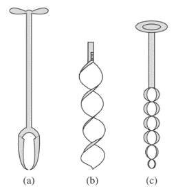
Figure 6.3. Auger Drilling (Gangopadhyay, 2013).
Wash Boring
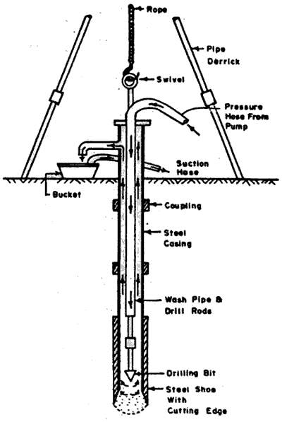
Wash boring is an affordable technique used for getting a general idea of the subsurface condition of the soil (Gangopadhyay, 2013). It is for all types of soil except gravel and boulders. As shown in Figure 6.4, the method includes the use of a casing with about 50 to 100mm diameter and depth of 1.5 to 3m, which is driven to the ground; however, for clayey soil, the casing is not required; however, the sample taken in this process is a highly disturbed sample which means can result in rough data (Harding, 1949).
Figure 6.4. Wash Boring(Gangopadhyay, 2013).
Rotary Drilling
Rotary drilling is suitable for both hard and soft type of soil. As seen in Figure 6.5, it uses hydraulic equipment and a core barrel to obtain ground samples. In this method, a drill bit, fixed to the lower end of the rods is rotated and is always kept in firm contact to the bottom of the hole (Bolton et al., 2002). Afterwards, the broken rocks and soil are removed by pumping drilling mud water through the drills rods and up the borehole, which collects the sample for soil. Unfortunately, this method is more complex and complicated than the other methods; thus, require more capital cost for equipment and the operator should undergo training (Harding, 1949).
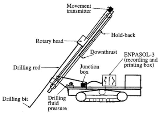
Figure 6.5. Rotary Drilling (Bolton et al., 2002)
Percussion Drilling
Percussion drilling is for granular and cohesive soil. It contains a heavy drilling bit as shown in Figure 6.6. in the form of the chisel at the end part of the machine and makes an up-and-down motion (Gangopadhyay, 2013). Afterwards, the cutter lowered to the borehole, and it breaks the soil in the soil into small fragments (Harding, 1949). The borehole of this type of drilling can reach up to 30 to 40 m, and the hammer used for that method is 120 kg and drops from 1 m. Then count the number of blows for each 20cm penetration for determining the compactness of the soil. The barrel used for that method worked as the shoring mechanism and used for extracting the material.
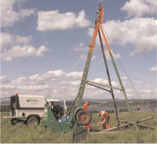
Figure 6.6. Percussion Drilling (Harding, 1949).
Trial Pits
Trial pits are shallow excavations with a depth not greater than 6m. Also, it is usually done by hand or a mechanical excavator as shown in Figure 6.7. (Harding, 1949). The primary purpose of trial pits is for block sampling and detection of services before borehole excavation. It commonly used in exploring backfilled areas and site overlain by natural deposits. However, it is only suitable for dry areas wherein hand cut samples are allowed, which minimises the disturbance of the sample.
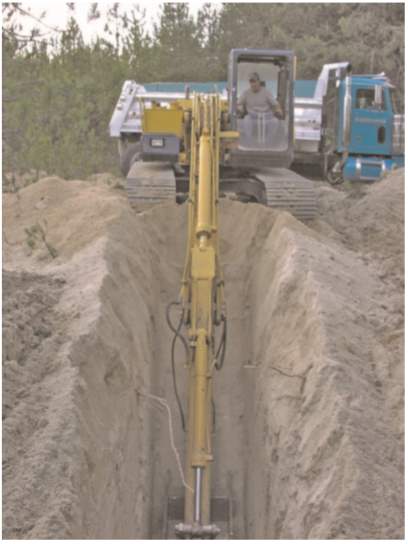
Figure 6.7. Trial Pit Excavation (Simons et al.,2002).
In-Situ Test Methods
In- situ methods are considering analyzing the soil condition instantly. In the situation of sampling technique of soil, the process will take time to receive an information and result from laboratory testing process. Base on site condition and classification of construction, we have several types of in- situ tests method in recent years(Wang et al. 2015). The list of some effective in-situ method was described in the figure below:
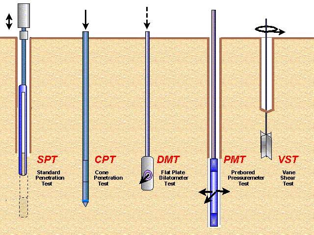
Standard Penetration Test (SPT) method
The Standard Penetration Test (SPT) is one of effective methods that are commonly use in the world. It seen as the oldest in-situ method which was created and developed at 1902. It has a high effective for granular soil and other type of soil and ground. The result of this test provide information about soil properties, liquefaction properties and dimension of foundation(Clayton 1995). Moreover, this in-situ method was mentioned in Australian standard (AS 1289.6.3.1). This method aims to identify the quantity of blows which is designed for penetration, the factor known as penetration resistance ‘N’. Next, the penetration resistance factor “N” will collate with other factors like density, settlement and fiction angle. A value of N depends on the quantity of blows to drive at least 30cm of split spoon sample. On the other hand, the SPT test may become the best method in case of sample tubes was empty because of clean sand deposits.
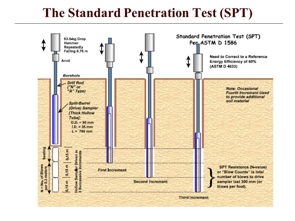
Figure: 7.1: Standard Penetration Test (SPT)
The figure above describes the Standard Penetration Test (SPT) and its toolset:
- Drilling Rig
- Tripod
- Drop Harmer (65 kg or 140 lbs.)
- Guiding Rod
- Extension Rod
- Split Spoon (tube)
- Anvil (driving head)
Procedure
The important point of this test is the thick-walled sample tube. The external diameter of this tube 50mm and 35mm for internal diameter(Jha & Suzuki 2009). The weight of metal harmed usually is 65 kg or 140 lbs, it is setup from 760 mm above the ground level.
The quantity of blows is the main factor that affect to the result of the test by inserting the tube to the 75 mm in to the ground and 450mm is the maximum depth.
Then the penetration factor “N” value will be calculated by plus the requirement of quantity of blows to penetrate the soil sampler in the last four 75 mm increment, the maximum of blow not must be more than 50.
If the total of blows is more than 50, then the test must be stopped to measure the penetration in millimeters. The formula of penetration factor “N” is proposed below:
N=
Moreover, the relationship between N and relative density was described in two figures below:
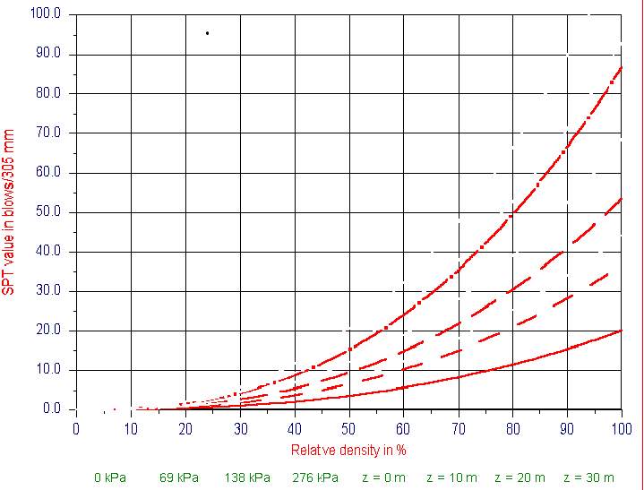
Figure 7.2. Relationship between penetration factor N and Relative Density ( Miedema 1995).
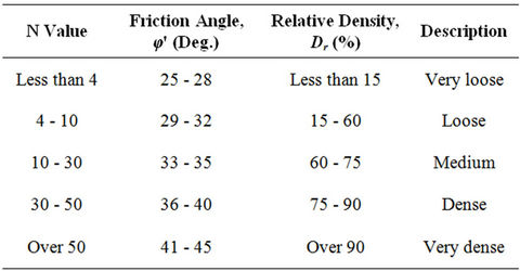
Figure 7.3. Relationship between Penetration factor N and Relataive Density
It is clear that the result of SPT test highly depends on the condition of soil and type. The result indicates that the accurate in case of fine sand and factor of environmental is also a crucial factor that affect to the SPT test.
Field Vane Test and Method
This is one of the famous in-situ methods. The test is focus on the bottom of the borehole, however, sometimes it also performs the ground surface. The test can determine the value of shear strength of soft cohesive soil. The shear test machines incudes four steel blades welded and the steel rod at the middle of machine. The depth between the blades and bottom of borehole is five times to the height of blade. It is usually from 50 to 100 mm. Then, the blade continues rotate with constant speed of 6 degrees per minute to identify the torque T where soil fails. The method takes a short time to be done and generally finish at the undrained condition. In that, the factor of undrained shear strength (Su) can be affected by torque and the sensitivity St. The relationship can be shown by the formula below:

In that,
H: the length of vane blade
D: diameter of vane
T: maximum torque
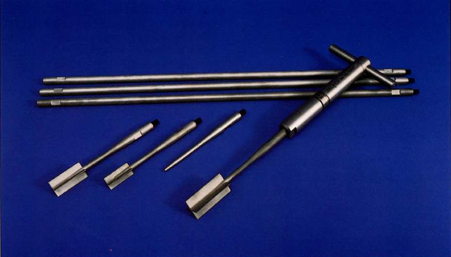
Figure 7.4. Vane Test Tools
Cone Penetration Test Method
As known as CPT, this test is used to determine the soil properties and condition of each layer of soil. This test is also determine the soil layer subject and liquification from different frequency of earthquake(Meigh 1987). The method includes a steel cone, total area is 1000 mm2 and requirement of apex angle is 60o. The users can easily move the cone with the internal steel rod to inside the external empty rod.
Procedure
The cone penetration test is described below:
- Firstly, it is necessary to move slowly the cone into the ground with a velocity from 1 to 2 cm/s.
- Secondly, cone penetration resistance qc is a resistance of the cone at any depth, and this factor is very important, so it need to be recorded by the sensors at the tip.
- Finally, both cone and the sleeve need to be inserted to ground and determine the resistance for this combination, and it is known as qt. The procedure can be recorded at any depth by applying tension load cells in sleeve.
The CPT not only determine the friction resistance but also identify the pressure of pore water(Zhang et al. 2018). Moreover, sometimes the CPT test also measure the temperature of soil and the speed of shear wave.
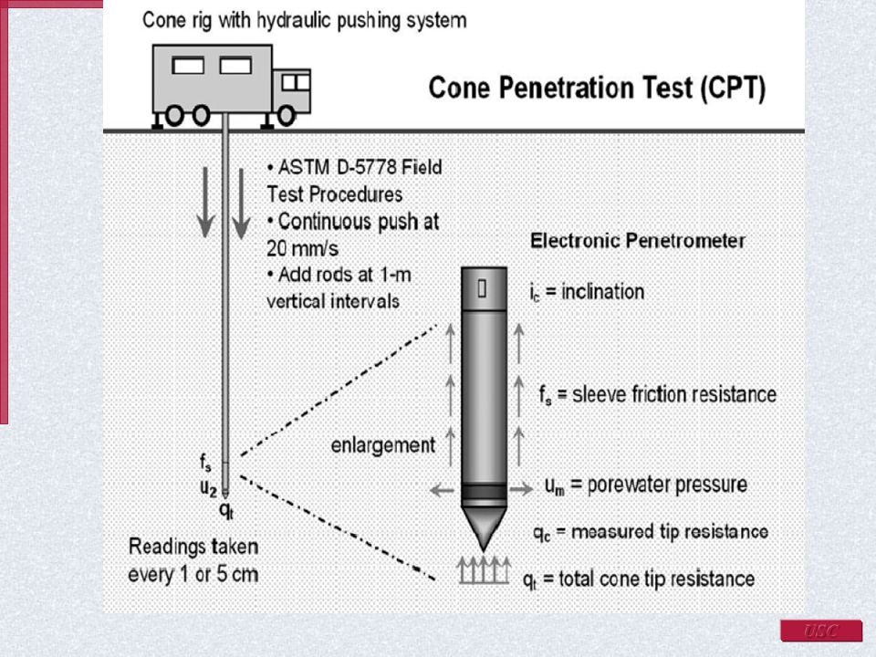
Figure 7.5. Cone Penetration Test (CPT)
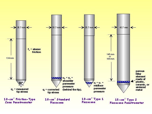
Figure 7.6. Types of Cone Penetration Test
Plate Load Test and Method
The plate load in-situ test is used to identify the bearing capacity and settlement of the soil from load. Firstly, the certain load will be applied to steel plate and measured the number of settlement base on the load increment. Then, the magnitude of the applied load on plate will increase until the plate shrinks quickly(Boyle 1992). The total magnitude of load will be separated into the cross-section area of the steel plate and the bearing capacity will be calculated due to the given soil (Nigli 2015). The bearing capacity need to multiply with some safety factor to get safe bearing capacity of the soil.
The equipment used for Plate Load Test are given below:
- Plate
- Pump
- Hydraulic jack
- Dial Gauges
- Pressure Gauge
- Tripod
- Plumb bob
- Equipment for loading platform
- Loading Columns
Procedure
Firstly, the excavation need set up to determine the depth. The pit size needs to be more than 5 times the size of the plate
Secondly, at the center of the pit, the user will create a small hole or depression and the size of the hole is similar with the size of plate. Then, at the bottom, the hole should have relative to the foundation level.
Thirdly, the ratio between depth and width of loading zone should be similar with the ratio between depth and width of the foundation(Noor, Islam & Haider 2015). The thickness of bearing plate must larger than n255m and the dimension can be from 300 to 750 mm. There are two main types of load that applied to the steel plate at the central column:
- Gravity (Reaction Loading)
- Truss Loading
Finally, there are two dial gauges to record the procedure of settlement at the diagonal corners of the plate. Then the data collection of settlement is repeated until it reached the maximum load(Couetdic & Barron 1975). Generally, the magnitude of maximum load is 1.5 times the ultimate load, and approximately 3 time the bearing pressure
Gravity
The type of loads are usually dead loads like sandbag, iron, rock. During the procedure of this test, a loading platform will be attached on the top of column to determine the applied load. A hydraulic jack is used to create an applied load to loading platform.
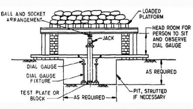
Figure 7.7. Setup step for Plate Load Test
Truss Loading Method
In this case, a truss plate form is built to determine the applied load. The truss is placed to the ground by the metal rope. When the applied load affects to the test plates, the truss start shrink and the dial gauges start measure the settlement of the plate. At least two dial gauges is required for the test to ensure the accurate result because of different settlement. The magnitude of applied load for the plate is usually 2kN or equal with 1/5 of the ultimate bearing capacity. The time of settlement is generally measure at the interval of 1.4; 10, 20, 40 and 60 minutes. The maximum applied load must be 15 times the bearing capacity. The figure below describe the Truss Method Plate Test
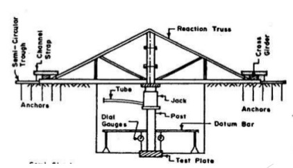
Figure 7.8. Truss method Plate Test
However, the truss method plate still has several limitations. Firstly, this test just only applys the prototype about the loading conditions, and the dimension of foundation may be bigger than it. The result of settlement and shear resistance can be affected by characteristic of stratum. Sometime, the result may lead to error because of the changing of soil properties in shallow depth. Because of these limitations, this test is usually applied for light or unimportant structure to identify the bearing capacity in the construction site. On the other hand, for crucial structure, the bearing capacity must be determined carefully by the other tests.
Dilatometer Test and Method
DMT or dilatometer is a type of test to identify the lateral stress, soil properties and its stiffness. The dilatometer test includes a stainless thin steel blade with 60 mm diameter at one side. The DMT is conducted by installing he blade and membrane to identify the deformation and pressure of the ground(Marchetti & Marchetti 2016). During the process of the test, the membrane is linked to a gas pressure unit that supply pressure to inflate the membrane. There are two types of measurements: first one is the requirement pressure to inflate the membrane against the soil as known as lift- off pressure, and the other one is the pressure that need to move the center of membrane 1.1 mm against the soil as known as deflection pressure(Choo et al. 2016). The DMT can test on soif soil and the hard rock. However, the size of soil should be smaller than 60 mm to get the better result from the test.
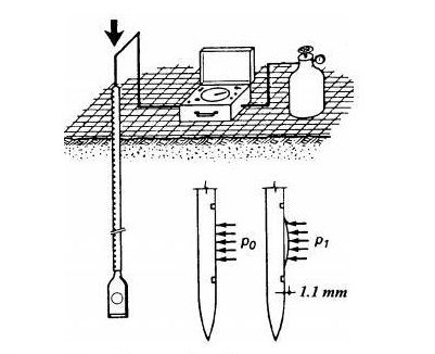
Figure 7.9. Dilatometer Test Method
Geotechnical Report’s case study
Giao et al. (2003) states that the big-scale reclamation work could be accomplished on the soft clays in the new land of the Nakdong River delta. Utilizing the new techniques is essential to be adopted a well evaluation after it is not able to show the geotechnical properties of the Pusan clays by drilling and sampling. So as to provide the map of thick, soft clay deposit, the 2D electric imaging technology are applied. Audited in this report is the laboratory resistivity testing and the electric imaging for the investigation of geotechnics in South Korea. This report also emphasizes the deficiencies linked with geotechnical aspect in Australia.
General information
Chung et al. (2012) states that the longest river of South Korea is Nakdong River. There is a difference in each area of Nakdong river when we consider the depositional environment. soft clay is the site which is selected for this project. The soft clay could absorb the radar signals and seismic. However, the seismic and radar signals are less agreeable for the investigation of geology. The physical characteristic of the soil is normally calculated in geotechnics since the most important part of soil foundations for infrastructure development is soft clays. Furthermore, soft clay could be collected easily from boreholes and delivered to the lab. Subsequently, the geotechnical studies could be conducted to evaluate the soft clay. Generally, in the geophysical investigation, the soft clay is not analysed. As mentioned above, regarding to analysing clay, the traditional geological methods could be easy the geophysical method. Fortunately, an advanced soil testing tool is created by the cooperation of geotechnical engineers and geophysicist.
Regarding to the DC electric, there are two methods such as Vertical Electric Sounding (VES) and the Electric Profiling (EP).
The two techniques utilize 4-electrode configuration. The adjustment of possible resistivity with depth is analysed by the utilized of the vertical electric sounding techniques mostly. The space of the electrode is slightly extended in to the two sides from the centre. Turning to the electric profiling technique, the space of the electrode is constant. In this technique, the space of electrode would move along with the survey line to distinguish the lateral heterogeneity.
The two techniques are widely utilized in ore deposits exploration and the studies of geology. Stefanesco et al. (1930) states that there is a limitation of the vertical electric sounding. Layered medium horizontal is assumption which could not happen practically. On the other hand, there is also a limitation of the Electric Profiling technique. This technique only access one-depth level information. Moreover, the two techniques could acquire a limited quantity of data points. In addition, the two techniques also access model from the information which is given low resolution for dense deltaic deposits. This replace for the silty, sandy and clay with a smaller resistivity. Thus, the geotechnical projects could not achieve a positive result by utilizing these two techniques.
The method electric imaging
Improving the modern resistivimeters such as SYSCAL, ABEM with higher certainty and automatic benefit of casual potential in order to achieve better readings of DC electric signals in the deposit of soft clay. The positive type of electrode configuration browses subsoils multiple times along the survey line. That is the primary advantage of DC electric imaging technique. Schlumberger, Wenner or dipole-dipole are the main example. The electrodes are remained constantly in the first browse. After that, the space is slightly incline to maximum level until the last browse. Reynolds (2011) states that there is a deeper understanding for automated array and geoelectric scanning.
Barker (1981), Van Overmeeren & Ritsema (1988) and Turnbull & Olayinka (1990) utilized the electric imaging technique in practical situation initially. There are some different examples for electric imaging technique (Adbul Nassir et al, 2000; Loke, 1999). However, in order to apply the electric imaging technique for soft clay deposits and the project of ground improvement, there are not many examples for that. The combination of the electric imaging survey and the calculations in laboratory of the electric resistivity of samples are difficult to investigated by survey. It is easy to find the method of laboratory setup in textbook or articles. However, it is hard to find the information result of the electric resistivity for the soft clay. The broadly application of the electric imaging technique for the soft clay could be limited. The application of the electric imaging solution for analysing the Pusan clay could be exhibited in this report. The following ideas are the scopes for that.
- Creating a map for the Pusan clay deposits for applying the geoelectric imaging. Extending that application to Nakong river basin reclaim the improvement of new land for more decades.
- Measuring the electric resistivity of Pusan clay by utilizing the simple testing set up.
- Comparing the outcomes of the electric resistivity from the samples which are collected from worldwide and from Pusan clay. So as to build the information of the soft clay resistivity, it is essential to utilize the values which are obtained from the different types of soft clay.
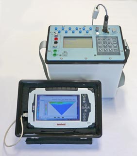
Figure 8.1. The tool SYSCAL Electric Imaging
Reclamation tasks and the Pusan clays engineering geology
Pusan is in the shoreline of South Korea. It is the second biggest city and main harbour of South Korea with 750 km2 and 3.8 million people. So as to develop the Pusan and suburbans. There is a project of new land development of Nakdong river which is proposed by the government. In early 1990s, the reclamation work was beginning in Nakdong River plain and some areas such as Noksan, Jangyu, Gadukdo, Shinho, i.e. (Figure 18)
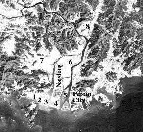
Figure 8.2. The Nakdong River plain (Giao et al. 2003)
The Soil profile in Nakdong River:
- Sandy Soil
- Alluvial silty
- Pusan clay deposit
- Sandy layer
The arrangement of Quaternary alluvium was dropped on the weathered rock layer which is followed by the Cretaceous bedrock. Rhyolites, Granites, Andesites are the main parts of it. Silty and sandy soil could not lead to the consistency of the top layer. However, there are Pusan clay in the ground surface. In the past, the active tectonic movement led to the appearance of the bedrock of the experiment site. There was a significant tectonic problem near the Nakdong River. The drainage arrangement and the structure lines are nearby. They trend to north to south. It is the mature step when we concern the fluvial erosion cycle. Generally, the clay thickness ranges from 20m to 40m. In some area, the thickness could be 70m (near the river).
Issues of Geological & solutions
Reclamation works consider embankment which were constructed on the soft clay as filling materials. Under the impact of surface loading, the soft clay deposits are compressed since good pore water which is compressed will bring about the settlements. Vertical drain is set-up to enhance the acceleration of the process of compression. That reduce the reclamation time or the construction. The clay deposit thickness would influence to the length and the spacing of the vertical drains significantly. That leads to the creation of Pusan clays map in order to search the appropriate ground improvement. However, there are some issues which relate to the Pusan clay geotechnical analyse. The following geophysical solutions could be utilized to solve these problems above.
- Generally, the thickness of Pusal clays could reach to 70m. In addition, the sampling could be finished at appropriate depth level. There was a lack of all way to the ground in the completed geotechnical soil profile.
- According to Tanaka et al. (2001), there are different depositional environments which are derived from different behaviour of soil in he sublayers of the Pusan clay.
- The soft and sensitive Pusan clay could be disturbed when storing, testing and transporting. Hence, the desirable results need a non-destructive test solution.
- Chung et al. (2012) states that there are short time changes of the Pusan clay thickness. As a result, prior to constructing the embankment and constructing the vertical drains, it is essential to map the Pusan clay.
- The electric imaging solution is the best solution to search the affected areas.
Utilizing the geoelectric imaging in order to map the deposits of soft clay
Location
There are 4 reclamation areas where the geoelectric imaging was applied such as Kimhae, Jangyu, Eulsookdo and Yangsan. The following figure will illustrate the layout of the four sites.
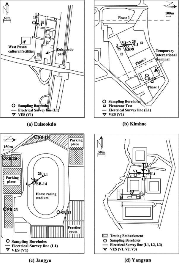
Figure 8.3. Study Sites and Locations
Procedure of field and facilities
Utilizing the SYSCAL R2 resistivity is applied for the electric imaging solution. The power from the booster would be used to run the SYSCAL R2. It also requires a system which could transfer the AC 220 V to DC voltage. Generally, multiple electrodes and multiple cables are essential for the geoelectric imaging. However, geoelectric imaging is done by crew members. It is expensive in order to use the multiple electrodes and cables. Therefore, manual electric imaging might be a practical advantage. Manually electric imaging line could be calculated. The following figure could be provided in order to understand deeply the electro spacing and procedure of field.
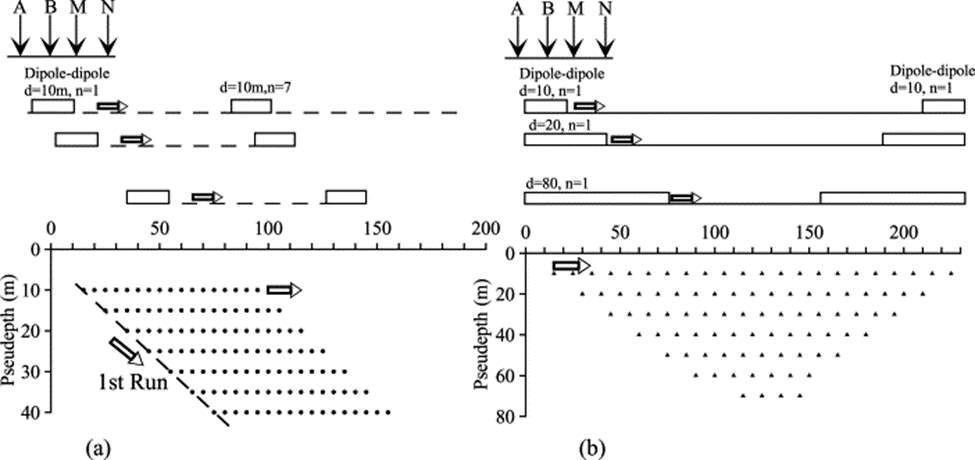
Figure 8.4. Electric imaging procedure in the field. (a) Moving dipole-dipole electric profiling. (b) Dipole-dipole electric imaging (Giao et al. 2003)
Results
According to Loke (1999), Both solutions of inversion such as I1 & I2 – norm inversion solution were utilized. Generally, I2 is utilized for gradual change. I1 is utilized for sharp contrast in subsurface resistivity. The both results were similar. The following figure will show the outcome of Eulsookdo site.

Figure 8.5. Outcomes of electric imaging
Electric resistivity laboratory measurement
The Pusan electric resistivity values were low. It varies from 1 Ω m to 3 1 Ω m. Sometimes, the data could be less than 1 mV. That is the reason why it is essential in order to check the data test. The samples core has 75 mm of diameter and 110 mm of length. The figure below will show the test equipment.
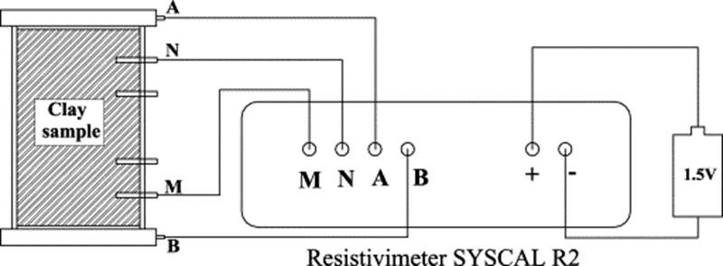
Figure 8.6. Testing setup of SYSCAL R2
Project decision
The following essential points could be studied from the project.
It is successful to map the Pusan clay deposits by utilizing the electric imaging. That distinguished the clayey, silty soils and sandy of the test.
By utilizing the manual solution of moving crew back and forth, it is easy so as to create the mapping of electric imaging rather than utilizing the multiple electrode and cables. There are two reasons for the success such as short electric imaging lines, flat ground and soft clay. It took 2 hours in order to browse a 250m long line and 10m distance.
The maximum dipoles spacing is more than three times of the depth of the electric imaging clay deposits. The spacing of dipole ought to incline to 120m for a clay deposit of 35m thickness. In addition, there should be a 500 m increase of the survey line.
Besides that, the time-dependent change of electric resistivity of the clay utilize the electric imaging in the period of ground improvement in the Kimhae International airport site.
In order to calculate the electric resistivity of the clay of Pusan parts, a simple install was utilized to calculate. On the field, the number of electric resistivity is suitable with the electric imaging.
Around 20 samples of clay soil were taken in around the world. After that, these 20 clay samples would be tasted for the laboratory electric resistivity. By using these samples, it is easy to build a database of the electric resistivity outcomes.
The outcomes states that in order to map the deposit of clay, the electric resistivity is necessary. Unit weight, salinity, water content are positive similarity between electric resistivity and the other parameter of geotechnics.
Conclusion
According to the facts described above, a proper geotechnical investigation can provide the faults that exist in the site and unexpected conditions which can be foreseen from the investigation result. Therefore, the faults can be avoided by a proper soil and foundation design depending on the type and quality of the soil.
Moreover, the different in-situ testing methods mentioned above can give accurate data in the soil investigation process depending on the type of soil and clay. As for the quick data and reliable results, the Cone Penetration Test and Dynamic Penetration Test are the most suitable methods to be used. Depending on the type of structure, different in-situ testing methods can be used and by combing the logging-based tests with other tests can produce great results as well.
References
Abdul Nassir, S., Loke, M., Lee, C. & Nawawi, M. 2000, ‘Salt‐water intrusion mapping by geoelectrical imaging surveys’, Geophysical Prospecting, vol. 48, no. 4, pp. 647-61.
Adeoti, L., Ojo, A., Adegbola, R. & Fasakin, O. 2016, ‘Geoelectric assessment as an aid to geotechnical investigation at a proposed residential development site in Ilubirin, Lagos, Southwestern Nigeria’, Arabian Journal of Geosciences, vol. 9, no. 5,p. 338.
Al-Khafaji, Amir Wadi Andersland, Orlando B., 1992. Geotechnical Engineering and Soil Testing. Oxford University Press. Retrieved from
https://app.knovel.com/hotlink/toc/id:kpGEST0002/geotechnical-engineering/geotechnical-engineering
Barker, R. 1981, ‘The offset system of electrical resistivity sounding and its use with a multicore cable’, Geophysical prospecting, vol. 29, no. 1, pp. 128-43.
Bolton, M., Gui, M., Soga, K., and Hamelin, J. 2002, Instrumented Borehole Drilling for Subsurface Investigation, Journal of Geotechnical and Geoenvironmental Engineering, vol 128, no 4, pp.283-291.
Boyle, W.J. 1992, ‘Interpretation of plate load test data’, International Journal of Rock Mechanics and Mining Sciences & Geomechanics Abstracts, vol. 29, no. 2,pp. 133-41.
Bruiad, J. 2013, Geotechnical Engineering: Unsaturated and Saturated Soils, 1st edn, John Wiley & Sons, Inc., Hoboken, New Jersey.
Chapter 9 – The Standard Penetration Test and the Static Penetrometer’ 1972, in G. Sanglerat (ed.), Developments in Geotechnical Engineering, vol. 1, Elsevier, pp. 245-78.
Choo, H., Lee, W., Hong, S.-J. & Lee, C. 2016, ‘Application of the dilatometer test for estimating undrained shear strength of Busan New Port clay’, Ocean Engineering, vol. 115, pp. 39-47.
Chung, S.G., Ryu, C.K., Min, S.C., Lee, J.M., Hong, Y.P. & Odgerel, E. 2012, ‘Geotechnical characterisation of Busan clay’, KSCE Journal of Civil Engineering, vol. 16, no. 3, pp. 341-50.
Clayton, C.R.I. 1995, The standard penetration test (SPT): methods and use.
Clayton, C. and Smith, D. 2013, Effective Site Investigation, Icevirtuallibrary.com. Viewed 17 October 2018,
Craig, C. 1996, Advances in Site Investigation Practice: Proceedings of the International Conference Held in London on 30-31 March 1995, Thomas Telford
Couetdic, J.M. & Barron, K. 1975, ‘Plate-load testing as a method of assessing the In-situ strength properties of Western Canadian coal’, International Journal of Rock Mechanics and Mining Sciences & Geomechanics Abstracts, vol. 12, no. 10,pp. 303-10.
Cruz, N. 2013, “Session report: Special uses of in-situ tests”, Taylor & Francis Books Ltd, Boca Raton, pp. 1139.
Fookes, P. 1967, Planning and stages of site investigation, Engineering Geology, vol 2, no 2, pp.81-106.
Gangopadhyay, S. 2013, Engineering Geology, Oxford University Press, pp. 248-249.
Gangopadhyay, Subinoy., 2013. Engineering Geology. Oxford University Press. Retrieved from
https://app.knovel.com/hotlink/toc/id:kpEG000002/engineering-geology/engineering-geology
Giao, P.H., Chung, S.G., Kim, D.Y. & Tanaka, H. 2003, ‘Electric imaging and laboratory resistivity testing for geotechnical investigation of Pusan clay deposits’, Journal of Applied Geophysics, vol. 52, no. 4, pp. 157-75.
Griffiths, D.H., Turnbull, J. and Olayinka, A.I., 1990. Two-dimensional resistivity mapping with a computer-controlled array, First break, 8(4), pp.121-129
Harding, H. 1949, Site Investigations Including Boring And Other Methods Of Sub-Surface Exploration. Works Construction Paper No 12. (Includes Plates)., Journal of the Institution of Civil Engineers, vol 32, no 6, pp.111-137.
Jha, S.K. & Suzuki, K. 2009, ‘Reliability analysis of soil liquefaction based on standard penetration test’, Computers and Geotechnics, vol. 36, no. 4,pp. 589-96.
Kolmykov, V. and Romanenko, E. 2014, On the Rational Form of Auger Drilling Bits, Chemical and Petroleum Engineering, vol 50, no 5-6, pp.387-389.
Loke, M. 1999, ‘Electrical imaging surveys for environmental and engineering studies’, A practical guide to, vol. 2.
Marchetti, D. & Marchetti, S. 2016, ‘Flat Dilatometer (DMT). Some Recent Advances’, Procedia Engineering, vol. 158, pp. 428-33.
Meigh, A.C. 1987, ‘Introduction’, in A.C. Meigh (ed.), Cone Penetration Testing, Butterworth-Heinemann, p. vii.
Noor, S., Islam, S. & Haider, B. 2015, SCREW PLATE LOAD TEST AND SPT IN THE ESTIMATION OF ALLOWABLE BEARING CAPACITY.
Reynolds, J.M. 2011, An introduction to applied and environmental geophysics, John Wiley & Sons.
Shilston, D., Parsons, A., Harrison, E. and Lee, K. (1998). Giants’ shoulders the cost effective use of geotechnical desk studies in civil and structural engineering, Pro. Seminar on The Value of Geotechnics in Construction (Nov 1998), Construction Research Communication Ltd, London. Pp. 25-36.
Simons, N., Menzies, B. and Matthews, M. 2002, A short course in geotechnical site investigation, Thomas Telford, London.
Stefanesco, S., Schlumberger, C. & Schlumberger, M. 1930, ‘Sur la distribution électrique potentielle autour d’une prise de terre ponctuelle dans un terrain à couches horizontales, homogènes et isotropes’, Journal de Physique et le Radium, vol. 1, no. 4, pp. 132-40.
Tanaka, H., Mishima, O., Tanaka, M., PARK, S., JEONG, G. & LOCAT, J. 2001, ‘Characterization of Yangsan clay, Pusan, Korea’, Soils and Foundations, vol. 41, no. 2, pp. 89-104.
Van Overmeeren, R. & Ritsema, I. 1988, ‘Continuous vertical electrical sounding’, First Break, vol. 6, no. 10, pp. 313-24.
Wang, C., Meng, X., Liang, W., Li, Y., Li, P. & Long, E. 2015, ‘Comparative Study of In-situ Test and Laboratory Test on Material Reflectivity’, Procedia Engineering, vol. 121, pp. 1932-8.
Zhang, X., Lin, C.-M., Dalrymple, R.W., Gao, S. & Canas, D.T. 2018, ‘Use of the Cone Penetration Testing (CPT) method to interpret late Quaternary tide-dominated successions: A case study from the eastern China coastal plain’, Continental Shelf Research, vol. 161, pp. 49-57.
Cite This Work
To export a reference to this article please select a referencing stye below:
Related Services
View allRelated Content
All TagsContent relating to: "Engineering"
Engineering is the application of scientific principles and mathematics to designing and building of structures, such as bridges or buildings, roads, machines etc. and includes a range of specialised fields.
Related Articles
DMCA / Removal Request
If you are the original writer of this dissertation and no longer wish to have your work published on the UKDiss.com website then please:

