Wireless Data Transfer Using Light Fidelity
Info: 9638 words (39 pages) Dissertation
Published: 9th Dec 2019
Tagged: CommunicationsEngineering
Abstract
Usage of light emitting diode (LED) is rapidly growing due to its reliability, low power consumption and high efficiency. In Visible Light Communication (VLC) system, LED is used for illumination; simultaneously it can be used for communication. The objective of this project is to study the VLC system and design a prototype to demonstrate the functionality of VLC system for audio and digital signal transmission through LED light beam. The VLC system consists of two main components which are transmitter and receiver. The transmitter is attached with LED and the receiver is attached with photodiode, such that, the signal can be transmitted through LED and received by photodiode. The design of the VLC system involved idea of generating negative voltage, signal amplification, compensating background light intensity, recovering attenuated signal. In this project, two prototypes i.e. VLC audio transmitter and receiver, VLC free space transceiver have been designed and constructed. These prototypes have successfully been demonstrated for transmission of audio signal and digital signal.
TABLE OF CONTENTS
Contents Page
Declaration i
Certificate of approval ii
Copyright iii
Acknowledgement iv
Abstract v
Table of Content vi
List of figures x
List of Abbreviations xi
CHAPTER ONE: INTRODUCTION` 1
1.1 Background 2
1.2 Problem Definition 2
1.3 Objective 3
1.4 Scope and Application 3
CHAPTER TWO: LITERATURE REVIEW 4
2.1 Previous Work 5
2.2 Related Theory 5
2.2.1 Visible Light Communication System 5
2.2.2 Technology of VLC transmitter 6
2.2.3 Technology of VLC Receiver 6
2.2.4 VLC Channel 6
2.2.5 Emission White Light Through LEDs 7
2.2.6 Photodiode 7
2.2.7 Standardization of Visible Light Communication 7
CHAPTER THREE: REQUIREMENT ANALYSIS 9
3.1 Project Requirements 10
3.1.1 Hardware Description 10
3.1.1.1 74HC14 10
3.1.1.2 LM386 10
3.1.1.3 MAX 232 11
3.1.1.4 USB to Serial Cable 11
3.1.2 Software Description 12
3.1.2.1 HyperTerminal 12
3.1.2.2 Proteus 13
CHAPTER FOUR: PROJECT DESIGN AND ARCHITECTURE 14
4.1 Block Diagram 15
4.2 Block Diagram Explanation 16
4.2.1 Analog Communication 16
4.2.1.1 Audio in/out 16
4.2.1.2 Amplifier 16
4.2.1.3 Boucherot Cell 16
4.2.1.3 Boucherot Cell 16
4.2.1.4 Transistor 16
4.2.1.5 LED/ Solar Cell 16
4.2.2 Digital communication 17
4.2.2.1 HyperTerminal 17
4.2.2.2 USB to Serial Cable 17
4.2.2.3 MAX232 17
4.2.2.4 74HC14 17
4.2.2.5 LED/ Photodiode 17
4.3 Circuit Diagram 18
4.3.1 Schematic Diagram 18
4.3.1.1 Schematic Diagram for audio transmitter 18
| 4.3.1.2 Schematic Diagram for audio receiver | 18 | |
| 4.3.1.3 Schematic Diagram for Trans-receiver | 19 | |
| CHAPTER FIVE: METHODOLOGY | 20 | |
| 5.1 System Methodology | 21 |
5.1.1 VLC Audio Transmitter and Receiver 21
5.1.2 VLC Trans-receiver 22
5.2 Interfacing of laptop and VLC system 22
5.2.1 Hardware 22
5.2.2 Software 23
5.2.2.1 HyperTerminal Communication Port Setting 23
CHAPTER SIX: IMPLEMENTATION DETAILS 25
6.1 Road-to-Vehicle Communication 26
6.2 Visible Light Communication for Advance Driver Assistant Systems 26
6.3 A Dual-use Visible Light Approach to integrated Communication 27
And Localization of Underwater Robots with Application to Non-
Destructive Nuclear Reactor Inspection
6.4 Study of Visible Light Communication System using RGB Lights 28
6.5 Visible Light Communication for audio & Video Transmission 28
CHAPTER SEVEN: RESULT AND ANALYSIS 30
7.1 Result and Analysis 31
7.1.1 Observation of LED Performance 31
7.1.2 Output of Solar Panel & Photodiode 32
7.1.3 Output of USB to Serial Converter 32
7.1.4 Received Signal VS Baud rate 32
7.1.5 All output stages of audio Transmitter and receiver 34
7.1.6 The Project Final Prototype 34
7.1.6.1 VLC Character transmitter and receiver 34
7.1.6.2 VLC Audio transmitter and receiver 35
CHAPTER EIGHT: CONCLUSION AND FUTURE WORK 36
8.1 Conclusion 37
8.2 Limitations 37
8.3 Further Enhancements 37
REFERENCES 39 APPENDIX 40
LIST OF FIGURES
Figure No. Name Page No.
3.1 74HC14 IC 10
3.2 LM386 IC 10
3.3 MAX232 IC 11
3.4 USB to Serial Cable 12
3.5 Hyper Terminal Interface 12
3.6 Proteus 13
4.1(a) Audio Transmission (Analog Communication) 15
4.1(b) Duplex Communication (Digital Communication) 15
4.3(a) Circuit of Audio Transmitter 18
4.3(b) Circuit of Audio Receiver 18
- 3(c) Circuit of Trans-receiver 19
- 1(a) Block diagram of VLC Audio Transmitter and Receiver 21
5.1(b) 3.5 mm audio jack plug 21
5.2(a) COM Port setting configuration for hyper-terminal 23
5.2(b) Sending symbols through hyper-terminal from transmitter computer 24
- 2(c) Received symbols in hyper-terminal to receiver computer 24
- Road-to-Vehicle Visible Light Communication 26
- General Architecture for a Full Duplex VLC System 27
- Architecture of the dual-use optical communication system 27
- System Outline by using RGB Lights 28
- 5(a) Transmitter Module 29
- 5(b) Receiver Module 29
- 1(a) Circuit representation of LED observation 31
7.1(b) Voltage waveforms across an LED for different frequencies 31
- 1(c) Waveform across an LED at 10MHz frequency 32
- Received Signal versus Baud Rate 33
- All Output Stages of Audio Transmitter and Receiver 34
7.4(a) Prototype for digital communication 35
7.4(b) Prototype for Analog Transmission 35
List of Abbreviations
| CMOS | Complementary Metal Oxide Semiconductor |
| EM | Electromagnetic |
| EIA | Electronic Industries Alliance |
| FTDI | Future Technology Devices International |
| IC | Integrated Circuit |
| IEEE | Institute of Electrical and Electronics Engineers |
| JEDEC | Joint Electron Device Engineering Council |
| JEITA | Japan Electronics and Information Technology Industries Association |
| KHz | Kilohertz |
| LED | Light Emitting Diode |
| Li-Fi | Light Fidelity |
| Mbit/s | Megabits per second |
| MHz | Megahertz |
| nm | nanometer |
| PCB | Printed Circuit Board |
| PSoC | Programmable System-on-Chip |
| PWM | Pulse Width Modulation |
| RC | Resistor Capacitor |
| RF | Radio Frequency |
| RGB | Red Green Blue |
| ROV | Remotely Operated Vehicles |
| RXD | Receiver Downstream |
| TIA | Telecommunications Industry Association |
| THz | Terahertz |
| TTL | Transistor Transistor Logic |
| TXD | Transmit Data |
| USB | Universal Serial Bus |
| VLC | Visible Light Communication |
| VLCC | Visible Light Communication Consortium |
| Wi-Fi | Wireless Fidelity |
CHAPTER-ONE
INTRODUCTION
1.1 Background
Visible Light Communication (VLC) is a wireless communication using visible light as a medium to transfer information. Li-Fi is a wireless communication system in which light is used as a carrier signal instead of traditional radio frequency as in Wi-Fi. Li-Fi is a technology that uses light emitting diodes to transmit data wirelessly. Li-Fi is a form of Visible Light Communication (VLC). VLC uses rapid pulses of light to transmit information wirelessly that cannot be detected by the human eye. Light is an electromagnetic wave which frequency spectrum lies between 400 THz to 800 THz or wavelength between 375 nm to 780 nm. LED has longer lifetime, high tolerance to humidity, smaller size and lower power consumption. Hence it is more environmentally friendly and does not cause any harm to humans. LED is used for illumination and at the same time, it also can be used for communication.
Over the past few years there has been a rapid growth in the utilization of the RF region of the electromagnetic spectrum. This is because of the huge growth in the number of mobile phones subscriptions in recent times. This has been causing a rapid reduction in free spectrum for future devices. Light-fidelity (Li-Fi) operates in the visible light spectrum of the electromagnetic spectrum i.e. it uses visible light as a medium of transmission rather than the traditional radio waves.
1.2 Problem Definition
Using visible light as a medium for data transmission entails many advantages and eliminates most drawbacks of electromagnetic wave which lies outside the visible light spectrum (400 -800 THz or 375-780 nm).
The telecommunication industry is continuously expanding to meet the human needs. However, bandwidth of EM/RF is limited and cannot keep up with the demand, i.e. telecommunication companies are running out bandwidth to transmit. Therefore visible light can be used as an alternative transmission medium to extend the available bandwidth for transmission.
Furthermore, visible light channel is free of charge. No company owns property rights for visible light and thus no royalty fees have to be paid. Hence visible light serve as an entirely free infrastructure to base a complex communication network.
In certain areas such as hospitals and flights, EM/RF devices are prohibited to avoid unwanted interference. Since VLC does not interfere with EM/RF. It can be used as wireless medium for communication in those EM/RF prohibited areas.
In term of security, visible light can transfer data more securely than EM/RF over short distances because it cannot be detected outside rooms or buildings, i.e. light does not penetrate the wall, thus making it easy to secure transmission.
1.3 Objectives
The objective of this project is:
• To study the VLC system and design prototype to demonstrate the functionality of VLC system audio signal transmission and digital signal transmission through modulated LED light beam.
1.4. Scope and Application
VLC system is a fresh technology which providing huge advantages over the existing wireless technology. Thus, VLC offer a wide research and applications. VLC technology has an impressive advantages over the existing EM/RF wireless technology. Especially when VLC willing to achieve the goal that EM/RF couldn’t achieve. For example, VLC allowed in EM/RF prohibited area such as hospital or aircraft and etc.
Application of Visible Light Communication System are Road-to-vehicle communication, Visible Light Communication for Advance Driver Assistant Systems, a Dual-use Visible Light Approach to integrated communication and Localization of underwater Robots with Application to Non-Destructive Nuclear Reactor Inspection,
Study of Visible Light Communication System Using RGB Lights, Visible Light
Communication for Audio and Video Transmission.
CHAPTER-TWO
LITERATURE REVIEW
2.1 Previous Work
Wireless communication is a technology that involves point to point communication over a distance without wires, cables or any other forms of electrical conductors. Wireless communication technology includes cellular radio, personal communication systems, satellite, mobile phone, wireless modems, local area networks and multipoint distribution systems for wireless delivery of television or internet service. The latest addition to the family is Visible Light Communication (VLC).
VLC was discovered in the year 1880 by Alexander Graham Bell through his Photo phone demonstration where he transmitted speech via modulated sunlight over several meters [1]. The research on VLC only started in year 2003 by Nakagawa Laboratory, in Keio University, Japan by using LEDs to transmit data through visible light. Since then, there had been several successes which shows that VLC is able to replace the RF/EMF with better performance. In January 2010, a team of researchers from Siemens and Fraunhofer Institute for Telecommunication had demonstrated transmission at 500Mbit/s with a white LED over a distance of 5meters and 100 Mbit/s over a longer distance using five LEDs [1] accident, etc. then we were stroked by the idea of introducing differently able person in the agricultural field based on the concept of making or creating job opportunity or in other sense making differently able person able to work as like as normal person in the field of agriculture with the support of technology. As, in the field of rehabilitation and assistive technology a lot of work has been done, here we have created working scenario of differently able person working in the field of agriculture as like as normal person.
2.2Related Theory
2.2.1Visible Light Communication System
VLC system is a communication system using visible light to transmit information. The system consists of a transmitter and a receiver with the LEDs at the transmitting end and the photodiode at the receiving end.
The luminescence intensity of the LEDs will be modulated according to data signal at high frequency at transmitter. The receiver (i.e. the photodiode) will then convert the light intensity into an electrical signal in order to receive the transmitted data.
2.2.2 Technology of VLC transmitter
The VLC transmitter is also known as an optical transmitter device which is used to transmit information by using visible light over the transmission medium. The digital data signal is passed to a data encoder that modulates the signal with the purpose of switching the LEDs at the expected rate of transmission. The modulation method used must offer higher light intensity than the background light. Therefore, the modulated light should be as bright as possible.
VLC data rate is limited by the switching speed of the emitter LEDs. Furthermore, long distance communication is limited by the transmitted power and background light sources.
2.2.3 Technology of VLC Receiver
The VLC receiver is an optical receiver which photodiode used to receive transmitted information. The photodiode converts the modulated visible light spectrum into an electrical signal. The converted signal is capable of being processed by the demodulator.
Amplification is required to improve the resolution of the received signal. A filter can be introduced to the system to reduce the noise component of the received signal. The final processed signal should correspond to the transmitted light pulses which are then decoded in the final output signal.
2.2.4 VLC Channel
The emitted light from LED carries data information in wireless medium. Thus the intensity of the light of the emitter becomes an important parameter on which the range of transmission depends.
In the transmission channel, the visible light does not get distorted by any RF signal. However, there are many external noise sources such as sunlight, street light and existing incandescent light, which should be taken into account in the design. The interference caused may distort the intensity of the emitted light and cause the false triggering. Thus error will occur at the receiver end. An optical filter can be introduced to minimize this unwanted error.
2.2.5 Emission White Light through LEDs
The visible light wavelength is in between 375nm to 780nm. However, the characteristic of white light is that it is an electromagnetic radiation composed of a fairly even distribution of all of the frequencies in the visible range of the spectrum.
Therefore, it appears white to human eye.
LEDs are used as indicator lamps in many devices and mostly for illumination. When a LED is forward biased, the electrons and holes within the semiconductor are combined, thus, releasing energy in the form of photons.
2.2.6 Photodiode
Photodiode is a type of photo detector which is able convert the light into either current or voltage. Hence, the functionality of photodiode is same as traditional solar cell. Photodiodes are semiconductor devices responsive to high energy particles and photons. Photodiodes operate by absorption of photons or charged particles and generate a flow of current in external circuit, proportional to the incident power. Photodiodes can be used to detect the presence or absence of minute quantities of light. A photodiode is a p-n junction. When photon strike on the diode, it’s excites an electron. Therefore create a free electron or positively charged electron hole. This mechanism known as inner photoelectric effect. If the absorption occurs in junction’s depletion region, or one diffusion length away from it. These carriers are swept from the junction by built-in field of the depletion region. Thus, hole flow toward the anode, and electrons toward the cathode, then the photocurrent is produced. The photo current is a sum of both the dark current and the light current. So the dark current must be reduced to ensure the sensitivity of the device.
2.2.7 Standardization of Visible Light Communication
The standard of visible light communication is important in practical application to avoid the mutual interference between different product and the problem due to interchangeability are expected when the different communication methods is used. Although the VLC does not infer with RF signal but it is necessary to consider the interference between the VLC devices against existing infrared devices.
In effort of standardization the VLC. Currently we have JEITA (Japan Electronic and Information Technology) standards and IEEE standards which working on the specification of PHY and MAC layers for VLC. VLCC (Visible Light Communication Consortium) working on visible light communication standards. In 2007, VLCC proposed two visible light standard to JEITA and the two proposals became JEITA standard in June 2007 [2].
Therefore, the proposed VLC standard at JEITA is the most fundamental standard in the free space visible light optical communication system. The objective of the proposed JEITA CP-1221 standard is to present and indicator in order to prevent the interference between different optical communication equipment and define a minimum necessary requirement in various visible light communication applications
[2].
The visible light communication system standard of JEITA CP-1221 proposed assumes the range of the wavelength of the light of a visible light communication to be 380nm-780nm, and allows an arbitrary wavelength range of each application in 1 nm accuracy. The standard uses the subcarrier method by modulating the light intensity by a specific frequency. Therefore, by using a different subcarrier frequencies, interference can be avoided.
However the second proposed standard JEITA CP-1222 [2], differs from JEITA CP122. It is restricts the subcarrier frequency t 28.8 kHz and it specifically suggests using SC-4PPM as modulation scheme. Thus, it requires cyclic redundancy checks for error detection and correction [2].
CHAPTER-THREE
REQUIREMENT ANALYSIS
3.1 Project Requirements
3.1.1 Hardware Description
3.1.1.1 74HC14
The 74HC/HCT14 are high-speed Si-gate CMOS devices and are pin compatible with low power Schottky TTL (LSTTL).They are specified in compliance with JEDEC standard no. 7A. The 74HC/HCT14 provides six inverting buffers with Schmitt-trigger action. They are capable of transforming slowly changing input signals into sharply defined, jitter-free output signals.
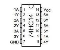
Figure 3.1 74HC14 IC
3.1.1.2 LM386
The LM386 is a power amplifier designed for use in low voltage consumer applications. The gain is internally set to 20 to keep external part count low, but the addition of an external resistor and capacitor between pins 1 and 8 will increase the gain to any value up to 200. The inputs are ground referenced while the output is automatically biased to one half the supply voltages. The quiescent power drain is only 24 mill watts when operating from a 6 volt supply, making the LM386 ideal for battery operation.
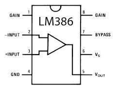
Figure3.2 LM386 IC
3.1.1.3 MAX 232
The MAX232 is a dual driver/receiver that includes a capacitive voltage generator to supply TIA/EIA-232-F voltage levels from a single 5-V supply. Each receiver converts TIA/EIA-232-F inputs to 5-V TTL/CMOS levels. These receivers have a typical threshold of 1.3 V, a typical hysteresis of 0.5 V, and can accept ±30-V inputs. Each driver converts TTL/CMOS input levels into TIA/EIA-232-F levels. The driver, receiver, and voltage-generator functions are available as cells in the Texas Instruments LinASIC library.
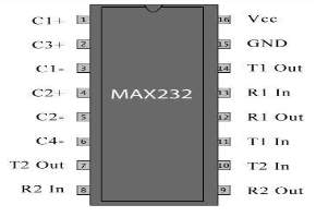
Figure 3.3 MAX232 IC
3.1.1.4 USB to Serial Cable
The USB-RS232 adaptor cables are a family of communication devices. This model, US232R, provides a simple method of adapting legacy serial devices with RS232 interfaces to modern USB ports. Each US232R adapter contains a small internal electronic circuit board which utilizes the FTDI FT232R, mounted inside a rugged plastic enclosure capable of withstanding industrial temperature ranges. The integrated electronics also include RS232 level shifters and TXD/RXD LEDs to provide a visual indication of data traffic through the adapter. The Cable incorporates a standard USBA device connector for connection to an upstream host or hub port. RS232-level signals, including modem handshake signals, are available on an industry standard DE9P connector. The maximum RS232-level data rate is 1MBaud.
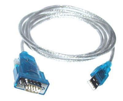
Figure 3.4 USB to Serial Cable
3.1.2 Software Description
3.1.2.1 Hyper-terminal
Hyper-terminal is the terminal emulation software included with the Microsoft Windows Operating System. The Hyper Terminal software had been used to command the computer in transferring and receiving the desired file. Hyper Terminal is a user friendly software. However, there is limitation in term of transmission speed. On the other hand, the configuration of software setting must synchronize with the receiving computer else the receiving computer will interpret wrong information from the sending computer.
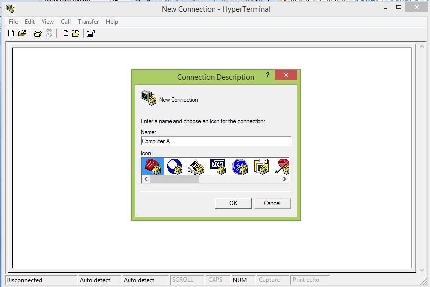
Figure 3.5 Hyper Terminal Interface
3.1.2.2 Proteus
Proteus, Lab Centre Electronics 1989-2011 has been used for the purpose of simulation and PCB design. This software is extremely helpful for testing and debugging the codes of different microcontrollers. Its library is rich for commercial ICs. Such commercial IC’s functionality and PCB packages come predefined. It is also user friendly as it helps to create new components for packaging and the simulation. Proteus had been very useful for us for the purpose of debugging and testing the codes as well as for making of PCB.
Figure 3.6 Proteus
The design of Proteus is organized around two goals:
- To make it easy to solve new model equations with existing numerical methods.
- To make it easy to solve existing model equations with new numerical methods.
CHAPTER-FOUR
PROJECT DESIGN AND ARCHITECTURE
4.1 Block Diagram
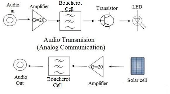
Figure 4.1(a) Audio Transmission (Analog Communication)
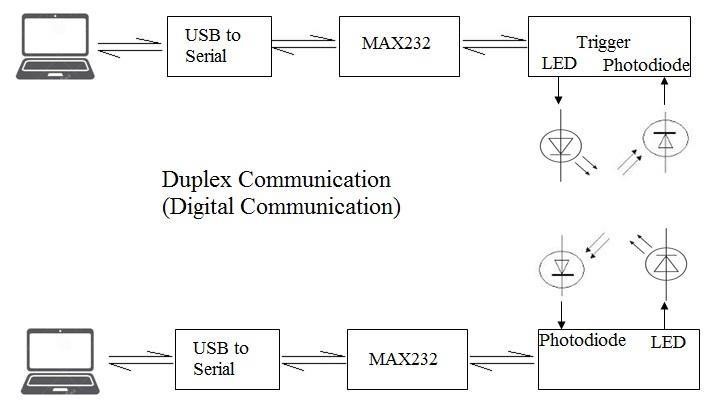
Figure 4.1(b) Duplex Communication (Digital Communication)
4.2 Block Diagram Explanation
4.2.1 Analog Communication
In this section of communication an audio signal has been used as an analog signal that has been transmitted from one end to another.
4.2.1.1 Audio in/out
A 3.5 mm audio jack has been used as a source of audio input at the transmitter section and a two pin connector has been used at the output section in order to connect the output to the speakers.
4.2.1.2 Amplifier
An operational amplifier IC (LM386, low voltage audio amplifier) has been used for the amplification process in both the transmitter and receiver section. This operational amplifier provides a gain of 20 which is far enough for transmitting the signal.
4.2.1.3 Boucherot Cell
A Boucherot cell (or Zobel network) is an electronic filter, used in audio amplifiers to damp high frequency oscillations that might occur in the absence of loads at high frequencies. Named after Paul Boucherot, a Boucherot cell typically consists of a resistor and capacitor in series that is usually placed across a load, for stability.
4.2.1.4 Transistor
A transistor is placed before the led which acts as a power amplifier for the led. The transistor 2N2222 helps in the current and voltage amplification of the output from the LPF. This amplification provides enough power to the led to carry the data fed at the input of the system.
4.2.1.5 LED/ Solar Cell
The amplified signal from the transistor is fed to the led which carries the data (audio signal) in the form of light. At the receiving end a solar cell is used which detects the light and converts the signal carried by light into the electrical form. Solar cell is used in order to acquire a higher area to maintain the line of sight between the transmitter and receiver for better communication.
4.2.2 Digital Communication
In duplex digital communication characters is transmitted from one laptop to another.
Software namely Hyper-terminal is used to as a trans-receiver source.
4.2.2.1 Hyper-terminal
Hyper-terminal is the terminal emulation software that commands the computer in transmitting and receiving the desired file. In this project characters are transferred from one laptop to another via wireless medium and through the emulation software.
4.2.2.2 USB to Serial Cable
The USB to Serial cable is used to interface between the laptop and the modules designed. This cable provides a simple method of adapting legacy serial devices with RS232 interfaces to modern USB ports.
4.2.2.3 MAX232
The MAX232 is used to convert the logic of the signal. The receiver converts TIA/EIA-232-F inputs to 5-V TTL/CMOS levels and vice versa. This helps in transmission of signal from one device to another.
4.2.2.4 74HC14
The 74HC/HCT14 is an inverting buffer with Schmitt-trigger action. They are capable of transforming slowly changing input signals into sharply defined, jitter free output signals. This helps in noise reduction at the transmitting end as well as the receiving end.
4.2.2.5 LED/ Photodiode
The signal from the trigger is amplified using a simple transistor BC547 which amplifies the voltage and current to drive the led. The led carries the information in the form of light which is received by the photodiode which converts the light signal to the electrical signal which can be further processed.
4.3 Circuit Diagram
4.3.1 Schematic Diagram
4.3.1.1 Schematic Diagram for audio transmitter
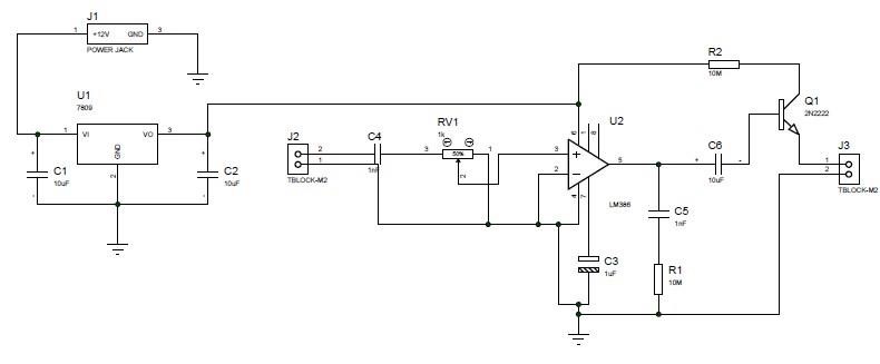
Figure 4.3(a) Circuit of audio transmitter
Schematic Diagram for audio transmitter consists of the main component as the LM386 operational amplifier. Basic circuit needed for the proper functionality of the amplifier is made. For the powering of the amplifier, Lm7809 voltage regulator is used. RC filter is added at the output of the amplifier. Also, a transistor 2N2222 is used at the output for power amplification.
4.3.1.2 Schematic Diagram for audio receiver
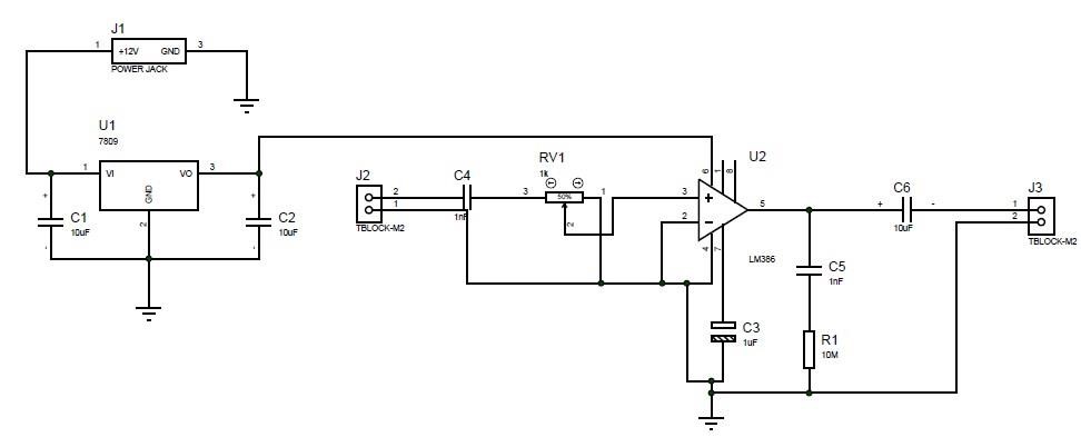
Figure 4.3(b) Circuit diagram of audio receiver
Audio receiver consists of the main component as the LM386 operational amplifier. Basic circuit needed for the proper functionality of the amplifier is made. For the powering of the amplifier, Lm7809 voltage regulator is used. RC filter is added at the output of the amplifier.
4.3.1.3 Schematic Diagram for Trans-receiver
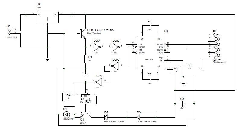
Figure 4.3(c) Circuit diagram of Trans-receiver
Trans-receiver consists of the two main components as the MAX232 and 74HC14. Basic circuit needed for the proper functionality of the trans-receiver is made. For the powering of the amplifier, Lm7805 voltage regulator is used. Also, a transistor BC547 is used for voltage and current amplification to drive the led.
CHAPTER-FIVE
METHODOLOGY
5.1 SYSTEM METHODLOGY
In this project, the design of VLC system is required to demonstrating the working of VLC system. Therefore, a VLC audio transmitter and receiver prototype has been constructed to demonstrate the transmission of audio signal and digital signal transmission between computers. Thus, the wireless VLC speaker has been designed.
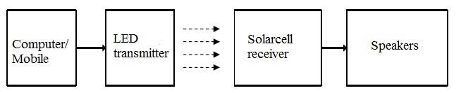
Fig 5.1(a) Block Diagram of VLC Audio Transmitter and Receiver
The second prototype of the project is the VLC transceiver to demonstrate the transmission of digital signal between two computers. The first computer must be able to transmit any data file type to the second computer via the designed transceiver.
5.1.1 VLC Audio Transmitter and Receiver
In demonstrating the transmission of audio signal through visible light, the intensity of the light emitted from white LED at transmitter has been amplified and the noise rectified according to the audio signal. The audio signal can be obtained from the computer/mobile through a 3.5mm audio jack plug as shown in figure 5.1(b).
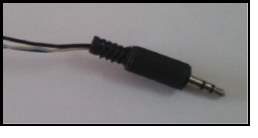
Figure 5.1(b) 3.5mm audio jack plug
At transmitting end, the bright white LED is used as the light source. The input signal is initially amplified to acquire higher gain of the signal for transmission. The amplified signal is passed through a Boucherot cell (Zobel Network) to filter out high frequency oscillation. Then the signal is passed to a transistor for current amplification to acquire enough current for led and passed to led whose intensity will be according to the pattern of obtained audio signal.
At the receiving end, solar cell is used as a photo detector to convert the emitted photon energy into electrical energy. Due to the arbitrary small current, the converted current has been amplified before the signal is fetch into the speaker. The speakers are used to play the received audio signal with the assistance of an amplification circuit designed for the speakers. The IC (Integrated Circuit) used in the amplification circuit is Mono Audio Amplifier LM386.
5.1.2 VLC Trans-receiver
The Transceiver prototype design is to achieve an objective in transmission of digital data between computers. Transceiver is a hardware used to interface with the computer for transmitting and receiving digital data.
USB to serial cable (prolific cable) functioned as the main hardware to interface the computer and transceiver circuit for transmitting and receiving digital signal. The capability of the designed Transceiver is able to modulate the emitted light beam according to the digital data and process the received digital data accurately before it’s been demodulated. The design criterion of VLC Transceiver such as signal amplification, light intensity control, background light elimination, and saturated signal recovery was concerned in the design. Bright white LED is used as the light source for emitting the modulated light beam.
At the receiving part, a photo diode is used. The received signal is amplified through the one of the op-amp of 74HC14. In solving the issue of background light and saturated signal. The buffer inverter 74HC14 is used to compensate the background light and recover the saturated signal.
However to ensure the intensity of LED light is adjustable and also the fraction of amplification gain is controllable. Hence the 20k potential meter is included in design.
5.2 Interfacing of laptop and VLC system
5.2.1 Hardware
As mentioned in section 5.1.3 USB to Serial Cable is used as the main hardware interfacing the computer and VLC Transceiver circuit. The main function of USB to
Serial Cable is use to fetch the digital signal from computer into VLC Transceiver.
Consequently, the digital signal is modulated with On-Off-Keying through the USB to
Serial Cable. Thus it is generating the digital on-off pulse at transmit pin in 3.5V or 5V.
The USB to Serial Cable, besides giving the friendly voltage configuration and also the sufficient supply voltage. It is also providing desirable output at transmit pin. The LED will be constantly lighting up if there is no data transmitted or at logic ‘0’ and when the digital data at logic ‘1’ the LED will off at very short time interval which is not detectable by human eyes. Thus, the Transceiver circuit can be simplified and the cost of design can be reduced. Since there is not require any other external circuit to ensuring LED is lighting up when there is no data been transmitted.
5.2.2 Software
The Hyper Terminal software had been used to command the computer in transferring and receiving the desired file. Hyper Terminal is a user friendly software. However, there is limitation in term of transmission speed. On the other hand, the configuration of software setting is necessary to synchronize with the receiving computer else the receiving computer will interpret wrong information from the sending computer.
5.2.2.1 Hyper-Terminal Communication Port Setting
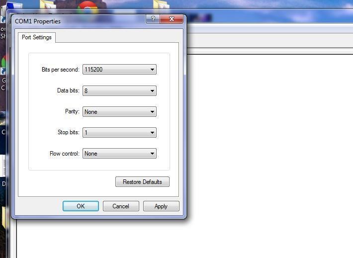
Figure 5.2(a) COM Port setting configuration for hyper-terminal.
/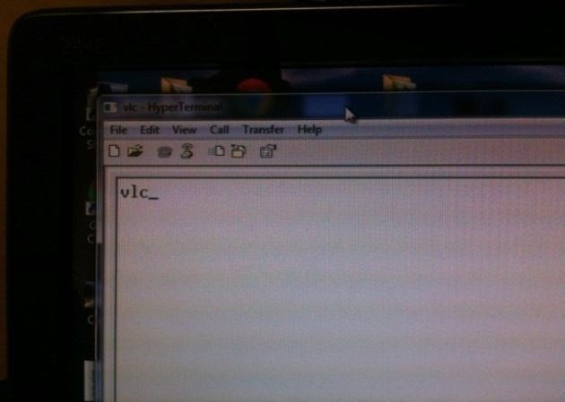
Figure 5.2(b) Sending symbols through hyper-terminal from transmitter computer.
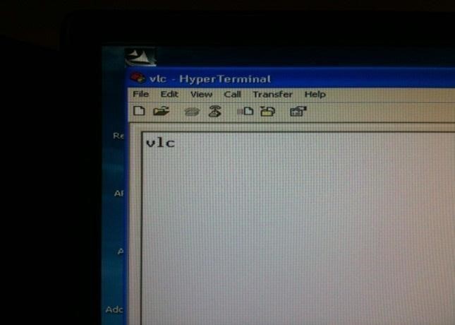
Figure 5.2(c) Received symbols in hyper-terminal to receiver computer.
CHAPTER-SIX
IMPLEMENTATION DETAILS
VLC system is a fresh technology which providing huge advantages over the existing wireless technology. Thus, VLC offer a wide research and applications. Some of the research and application will be reviewed below.
6.1 Road-to-vehicle Communication
Nowadays solid state LEDs is widely used in traffic signals and vehicle lights. Road to Vehicle communication is proposed and the illustration is shows in Figure 6.1.
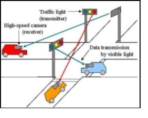
Figure 6.1 Road-to-Vehicle Visible Light Communication [3]
6.2 Visible Light Communication for Advance Driver Assistant Systems In this proposed idea, a camera is mounted before the front end of the car. The camera is used as the receiver to receive information from traffic lights. The advantage of using camera is that multiple data can be transmitted by the LEDs and received by High-speed Camera [3].
Optical Communications for outdoor communication has been discussed and elaborated [4]. Devices such as laptops and mobile phones can be used for transmitting and receiving information by using transceiver as shown in Figure 6.2.
Transceiver communication system designed through both LEDs and Photodiode. Intensity modulation was implemented to reach most practicable modulation. Various important design parameters were optimized by using intensive investigation based on gain variable over 100m of transmission range [4].
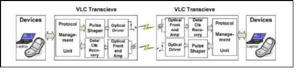
Figure6.2 General Architecture for a Full Duplex VLC System [4].
6.3 A Dual-use Visible Light Approach to integrated communication and
Localization of Underwater Robots with Application to Non-Destructive Nuclear Reactor Inspection
A VLC system for wireless underwater communication was proposed [5], for robotic inspection of nuclear power plants. The reactor exist in an underground environment as shown in Figure 6.3. A solution for maintaining the consistency line of sight to maintain a communication link was discussed in the published paper by [5].
An optical wireless link has been established between the remotely operated vehicles (ROV) and gateway station using LEDs and Photodiodes on both sides as depicted in Figure 6.3. Underwater ROV was used to communicate with the gateway station over water to transmit control signals. Both gateway station and ROV are capable of direction a light beam in three-dimensional space [5].
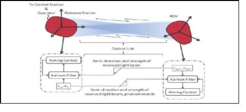
Figure 6.3 Architecture of the dual-use optical communication system [5].
6.4 Study of Visible Light Communication System Using RGB Lights
The prototype of demonstrating the VLC system using RGB LEDs and sensors [6] shows in Figure 6.4.
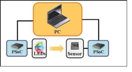
Figure 6.4 System Outline by using RGB Lights [6]
On the left, the RGB LEDs is used as signal transmitter and on the right the RGB sensor is used as a receiver. Thus, through the architecture which enable parallel communication and PSoC microcontroller is used to process the received signal. Through the PSoC microcontroller, it is efficiently reducing the need for extra circuits. PWM (Pulse width modulation) was used to switch the RGB LEDs at very high speeds. The characteristic of both the variation in color can change in intensity of each RGC LED and RGB sensor were analyzed to realize multiple value signals communication by using RGB color [6].
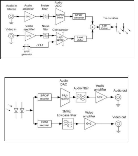
6.5 Visible Light Communication for Audio and Video Transmission
A VLC system able to transmit a high definition video and audio signal was proposed at [7]. The analogue video signal was modulated by using ultra high speed comparator in the transmitter. The analogue signal then was converted from analog to digital signal. Both the video and analog signals were transmitted using the illumination LEDs in the transmitter. The photodiode at the receiver senses the optical signals from the LEDs and convert it into electrical signals. The electrical signal is then amplified to recover the digital signal and converted back to an analog signal to video or audio signal. The illustration of block diagram is shows in Figure
6.5 (Transmitter Module) and Figure 6.6 (Receiver Module).
CHAPTER-SEVEN
RESULT AND ANALYSIS
7.1 Result and Analysis
7.1.1 Observation of LED Performance
The performance of a single LED was tested to examine the limitation and the setup is shown in Figure 7.1 (a) with the measurements in Figure 7.1 (b)
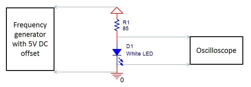
Figure 7.1(a) Circuit representation of LED observation
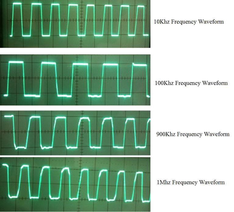
Figure 7.1(b) Voltage waveforms across an LED for different frequencies (2V/DIV).
The white LED with a forward voltage of 3.3V drives 20mA of current with resistor R1 in Figure 7.1(a) (DC offset of 5V from function generator). The waveforms across the white LED for different frequencies were observed using the oscilloscope in Figure 7.1(b). As seen from the waveforms shown in Figure 7.1(b) of different frequencies, the waveform maintains rectangular shapes at 10 kHz and 100 kHz, but when compared with 1MHz frequency, the waveform is distorted, hardly managing a square shape.
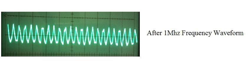
Figure 7.1(c) Waveform across an LED at 10 MHz frequency.
The LEDs have capacitance associated with the depletion region and the minority carriers that transport the charge. As a result, the driving signal has to charge and discharge capacitance. Due to the limited charging/discharging speeds, the frequency performance is limited. The waveform at 10MHz shown in Figure 7.1(c) requires the charge and discharge too fast for a capacitance to catch up with.
7.1.2 Output of solar panel and photodiode
The solar panel covers side of line of sight region also whereas photodiode needs exact line of sight. For the same intensity of light solar panel receives the signal from longer distance compared to that of photodiode. But the effect of noise will be greater in case of solar panel compared to that of photodiode.
7.1.3 Output of USB to serial converter
The data needed to transmit is generated from computer which is send through port of computer using USB to serial converter. This transmits the data in binary value serially to the transmitter. The LED in the transmitter then glows if the value is 1 otherwise the LED goes off. Similarly at the receiver side the received binary data is again send to computer via similar process.
7.1.4 Received signal VS baud rate
In this experiment character of ‘a’ is transmitted from computer with different baud rate. The output result at the receiving side after amplification by oscilloscope is measured. Therefore, according to the result in Figure 4.5 shows that, the signal at logic’0′ will saturate due to increase of transmission baud rate. This is because of ‘on’ and ‘off’ respond time become shorter. Thus, at higher baud rate, the time required for LEDs goes into logic ‘0’ does not entirely off the LED before it is lighting up at logic ‘1’. Or another problem which may be caused by sensitivity of the Photodiode used in this project. The LEDs has capacitance associated with the depletion region and the minority carriers that transport the charge. As a result, the driving signal has to charge and discharge capacitance. Due to the limited charging and discharging speeds, the frequency performance is limited. Thus as shown in Figure 7.2, at higher baud rate also mean at higher frequency. The charge and discharge time is too fast for capacitance to catch up. At the receiving side, the saturation may be caused by slow time constant of the photodiode. Thus, the photodiode is too slow to catch up the receiving light pulse.
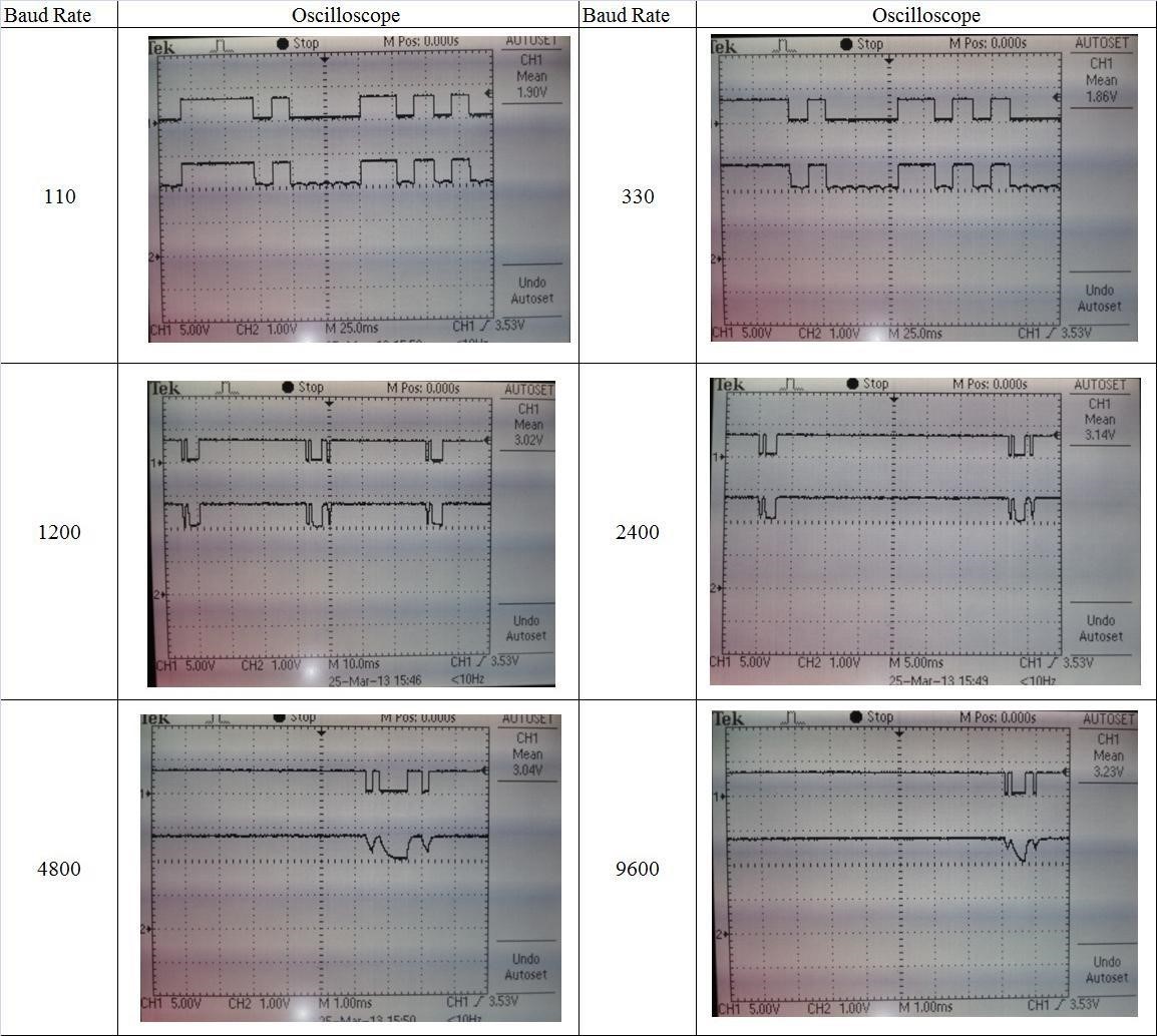
Figure 7.2 Received Signal versus Baud Rate
7.1.5 All output stages of audio Transmitter and receiver
In Figure 7.3(a) shows the transmitted signal from computer. At receiver side received signal by Solar panel with zoom in signal shown in Figure 7.3(b) and
7.3(c).The amplified signal through the Mono Audio Amplifier shown in Figure7.3 (d).
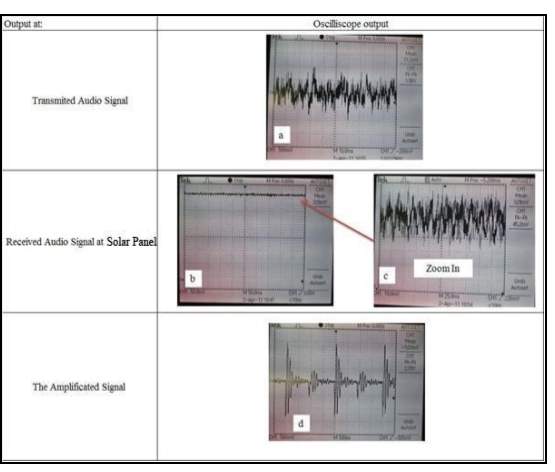
Figure 7.3All Output Stages of Audio Transmitter and Receiver
7.1.6 The Project Final Prototype
7.1.6.1 VLC Character transmitter and receiver
The constructed prototype for VLC Character transmitter is shown in Figure 7.4(a). The prototype is not much but just a module that acts as a receiver and transmitter medium between two computers. This module ensures the communication between the two different medium.
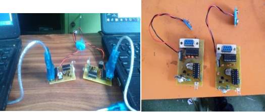
Figure 7.4(a) Prototype for digital communication
7.1.6.2 VLC Audio transmitter and receiver
The constructed prototype for VLC Audio transmitter is shown in Figure 7.4(b). This prototype can be used in audio transmission over led. The system provides a good quality output. This system design can be implemented in indoor places as a source of entertainment as well.
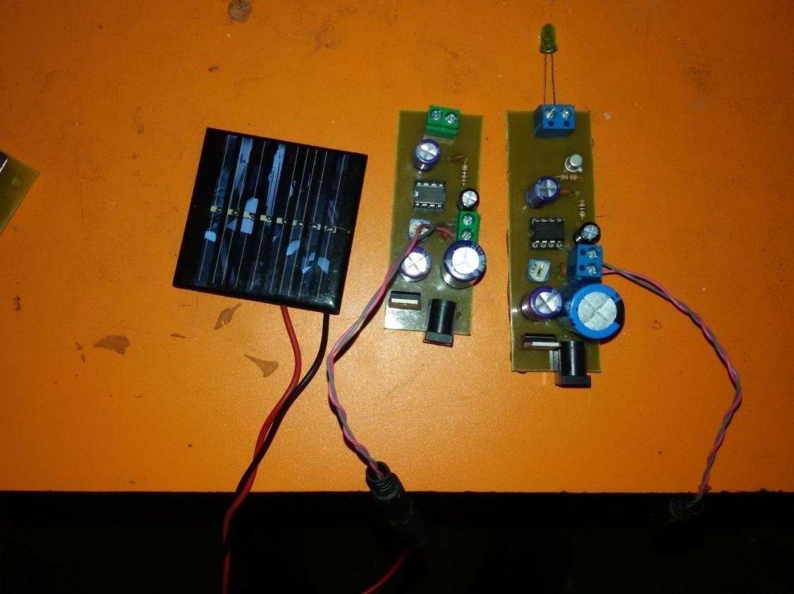
Figure 7.4(b) Prototype for Analog Transmission
CHAPTER-EIGHT
CONCLUSION AND FUTURE WORK
8.1 Conclusion
In this project, the technology of Visible Light Communication had been discussed. VLC technology has impressive advantages over the existing EM/RF wireless technology. Especially, when VLC is willing to achieve the goal that EM/RF couldn’t achieve. For example, VLC allowed in EM/RF prohibited area such as hospital or aircraft and etc. In this project, “VLC audio transmitter and receiver” prototypes have successfully implemented in this project. “VLC audio transmitter and receiver” had been designed to demonstrate the working of VLC system. The VLC audio transmitter and receiver demonstrate the transmission of audio signal from computer to speaker and the VLC free space Transceiver demonstrate the transmission of digital signal between two computers wirelessly by using visible light as transmission medium. The procedure of prototype implementation and design had been discussed in Chapter 4.
The designed prototype analysis and output had been presented in Chapter 6. Thus, the problem still exists and our prototype works best in dark environment. At the same time, the transmission speed in this project was slow due to sensitivity of photodiode and also LED used. Therefore, the higher sensitivity photodiode is recommended and fast respond LED is suggested in system design in order to achieve the higher transmission speed.
8.2Limitations
Every system has some limitations .Our system has too limitations. Limitations we have seen far are listed below.
- The surrounding light is causing noise.
- Due to the use of weak led intensity, long distance transmission is difficult.
8.3 Future Enhancements
Our system has some limitations, but the limitation can be achieved and the better system could be made. System can be further modified for the purpose of manufacture and made simpler for the differently able person.
Further enhancements can be as below:
• To enable the communication between the computer and a printer using
Visible light.
- Accessing internet using visible light.
- Data transmission between computers.
REFERENCES
- Pohlmann, C, “Visible Light Communictaion”, 2010
- Haruyama, S, “Visible Light Communications Consortium and its
standardization”, 2008
- S.Iwasaki, S. Premachandra. T.Endo;T.Fujii, M. Tamino and Y.Kimura, “Visible Light Communication Using High Speed Camera. Eindhoven, Netherlands”, 2008
- N. Kumar, L. A. Nero and R. L. Aguiar, “Visible Light Communication for Advanced Driver Assistant Systems”, 2006
- Asada, “A Dual-Use Approach to integrated Communication and Localization of Underwater Robots wih Application to NonDestructive
Nuclear Reactor of Inspection”, 2012
- T. Komitama, K. Kobayshi, K. Watanabe, T. Ohkubo and Y. Kurihara,
“Study of Visble Light Communication System using RGB LED Lights”, 2012
- D. K. Son, E. B. Cho and C. G. Lee, “Demonstration of Visible Light Communication Link for audio and Video transimission”, 2010.
- Lau Chih Yung, “Design and construction of visible light communication
System prototypes for audio and digital signal Transmission”, April 2013.
- Durgesh Gujjari, “Visible Light Communication” , August 2012
APPENDIX A: PCB DESIGNS
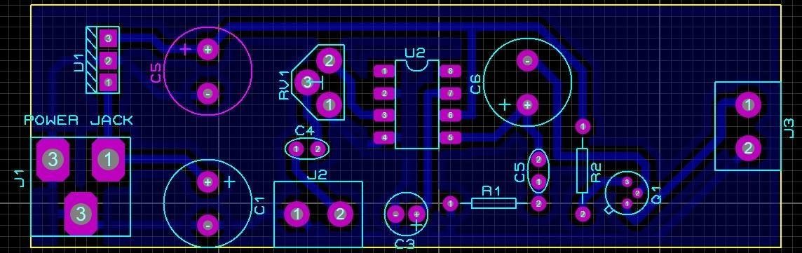
PCB for Analog Transmitter circuit
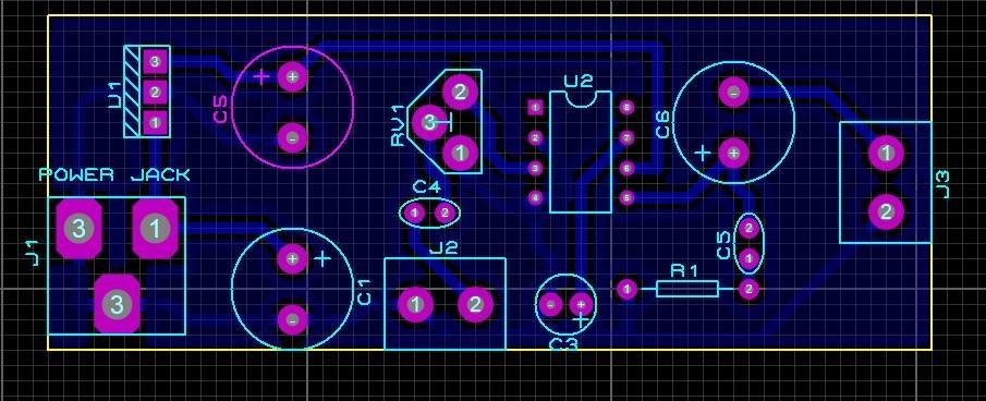
PCB for Analog Receiver circuit
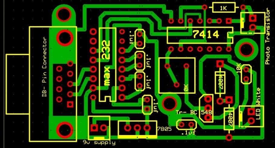
PCB for Trans-receiver Circuit
APPENDIX B: 3D Layout
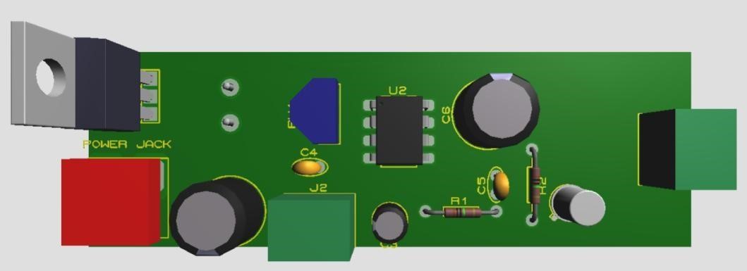
3D layout of audio transmitter
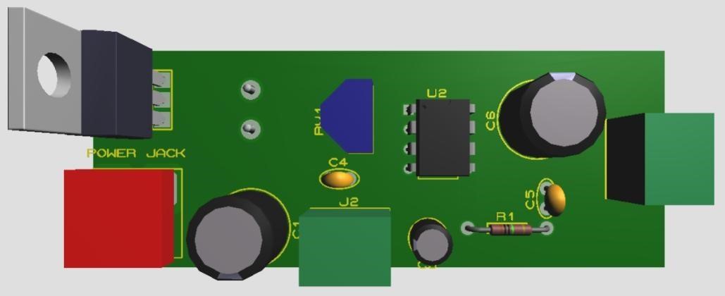
3D layout of audio receiver
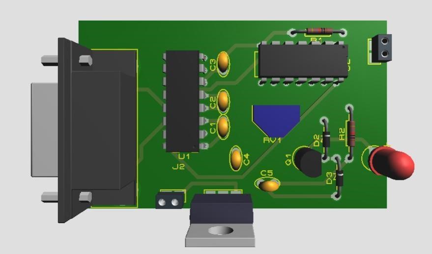
3D layout of Trans-receiver
Cite This Work
To export a reference to this article please select a referencing stye below:
Related Services
View all


Related Content
All TagsContent relating to: "Engineering"
Engineering is the application of scientific principles and mathematics to designing and building of structures, such as bridges or buildings, roads, machines etc. and includes a range of specialised fields.
Related Articles

DMCA / Removal Request
If you are the original writer of this dissertation and no longer wish to have your work published on the UKDiss.com website then please: