Web Portal for Neighbourhood Connections
Info: 13391 words (54 pages) Dissertation
Published: 15th Feb 2022
ABSTRACT
Now-a-days people get connected with their friends and relatives living far away from them with the use of social media, but not get informed with what’s happening in their area or society. This virtual world which connects us all impeccably is the online social media. Getting to know things as they happen with the people you fancy, at places distant, have never been easier as it is now. It’s like one can have his virtual presence from almost anywhere.
This web portal will exclusively develop by and for the private use for use of some residential society, with a view to use this website as a common platform for developing centralized databank , sharing common announcements, complaints, suggestions and make use of databank for the internal individual liasoning purpose.
The web application will help user to get connected with his housing society in order to view posts and announcements from other society members, together. The user can also post his view or photo gallery people for viewing. It will follow a registration process that will provide the user with his unique user_id. After that, the user can elect to log in through his accounts to view updates from his other society members.
The integral concept behind this application is “Why not get connected with our own neighbors and society members with a single account login and informed with useful updates of it?”
TABLE OF CONTENTS
Click to expand Table of Contents
1. Introduction
1.1 Introduction
1.2 Project Details
1.2.1 Project Profile
1.2.2 Project Overview
1.3 Purpose
1.4 Limitation
1.5 Aims & Objectives
1.5.1 Aims
1.5.2 Objectives
1.6 Technology Review
2. Technology Overview
2.1 Overview
2.1.1 .NET Framework
2.1.2 Visual Studio
3. About the System
3.1 Overall Description
3.1.1 Goals & Scenarios
3.1.2 Reliability
3.1.3 Availability
3.1.4 User Requirements
3.1.5 Functional Requirements
3.1.6 Non Functional Requirements
3.2 Feasibility Study
3.2.1 Technical Feasibility
3.2.2 Operational Feasibility
3.2.3 Economic Feasibility
3.2.4 Schedule Feasibility
3.3 Project Planning
3.3.1 Project Development Approach
3.3.2 Project Plan
3.3.3 Implementation Strategies
3.3.3.1 Business Model Canvas
4. Analysis
4.1 Analysis
4.1.1 Design Methodology
4.2 Design
4.2.1 Data Flow Diagram
4.2.2 Use Case Diagram
4.2.3 Sequence Diagram
4.2.4 Activity Diagram
4.2.5 Entity Relationship Diagram
4.2.6 Class Diagram
4.3 Data Dictionary
5. Implementation and Testing
5.1 Implementation
5.2 Testing
5.3 Test Cases
6. Conclusion & Future Work
6.1 Conclusion
6.2 Future Work
Appendix I: Bibliography
LIST OF TABLES
| Table No. | Table Name | Page No. |
| 1 | Project Profile | 11 |
| 2 | Data Dictionary of Admin | 44 |
| 3 | Data Dictionary of User | 44 |
| 4 | Data Dictionary of User family members | 45 |
| 5 | Data Dictionary of Unit master | 45 |
| 6 | Data Dictionary of Unit detail | 46 |
| 7 | Data Dictionary of Post | 46 |
| 8 | Data Dictionary of Post like | 46 |
| 9 | Data Dictionary of Post comment | 47 |
| 10 | Data Dictionary of Notice | 47 |
| 11 | Data Dictionary of Complain | 48 |
| 12 | Data Dictionary of Committee type | 48 |
| 13 | Data Dictionary of Committee master | 49 |
| 14 | Data Dictionary of Committee member | 49 |
| 15 | Data Dictionary of Event | 50 |
| 16 | Data Dictionary of Event subscriber | 50 |
| 17 | Data Dictionary of Gallery | 51 |
| 18 | Data Dictionary of Gallery image | 51 |
| 19 | Data Dictionary of Announcement | 52 |
| 20 | Data Dictionary of Announcement committee | 52 |
| 21 | Data Dictionary of Announcement like | 53 |
| 22 | Data Dictionary of Announcement comment | 53 |
LIST OF FIGURES
| Figure No. | Figure Name | Page No. |
| 1 | .NET Framework | 17 |
| 2 | SDLC by Spiral Development Model | 25 |
| 3 | Business Model Canvas | 28 |
| 4 | Context Level DFD | 34 |
| 5 | DFD Level 1 | 35 |
| 6 | Use Case Diagram 1 | 36 |
| 7 | Use Case Diagram 2 | 37 |
| 8 | Use Case Diagram 3 | 38 |
| 9 | Sequence Diagram | 39 |
| 10 | Activity Diagram 1 | 40 |
| 11 | Activity Diagram 2 | 41 |
| 12 | E-R Diagram | 42 |
| 13 | Class Diagram | 43 |
LIST OF ABBREVIATIONS
| Symbol | Abbreviations |
| No./no. | Number |
| VS | Visual Studio |
| VB | Visual Basic |
| .NET | Dot Net |
| DFD | Data Flow Diagram |
| ER | Entity Relationship |
| DD | Data Dictionary |
1. INTRODUCTION
1.1 Introduction
This web portal will exclusively develop by and for the private use for use of some residential society, with a view to use this website as a common platform for developing centralized databank, sharing common announcements, complaints, suggestions and make use of databank for the internal individual liasoning purpose.
The advantages of the Web application for user:
- Web application is easy to use.
- Easier installation and maintenance
- Powerful development framework.
- Open marketplace for distributing apps.
- Flexible core technologies
- Security
- Accessible anywhere
Considering the advantages of web applications, we decided to pursue developing a project on Web application.
1.2 Project Details
1.2.1 Project Profile:
| Project Name | COMMUNITIVE PORTAL |
| Project Duration | 10 months |
| Team Size | 1 members |
| Documentation | MS Word, MS Visio |
| Internal Guide | Prof. G.R.Prajapati |
Table- 1: Project Profile
1.2.2 Project Overview:
- This web portal will exclusively develop by and for the private use for use of some residential society , with a view to use this website as a common platform for developing centralized databank , sharing common announcements , complaints , suggestions and make use of databank for the internal individual liasoning purpose.
- There are dedicated society management committees in every housing society.
- The one little problem that enthusiastic resident face is ,can’t get informed with events or notices because of busy schedule.
- Thus, it would be better if one would be able to create only a single such application that would help to get notify and save time. This idea inspired our project.
- Communitive Portal will provide the user with hassle-free UI to manage account.
1.3 Purpose
- Ease of Access
- Update the user with events and notice of society.
- Since the user can view every different update in one place, it will reduce their time.
- Thus, system will increase the competence of work and management of time is properly done.
- The system will be available 24 hours for 365 days for social interaction.
1.4 Limitation
- It needs internet connection to interconnect with the system.
- The user must be mobile or computer knowledgeable to use the system.
- The user should carry with them Smartphone.
1.5 Aims and Objectives
1.5.1 Aims
- Create a user friendly web application.
- Web application should be used by every society member.
- User is able to set up a custom list of his favorite people for quick access.
- Real time viewing and notifications for latest feeds & updates.
1.5.2 Objectives
- The purpose of this analysis is to demonstrate the extent to which high-level systems concept and UML notation/semantics can be used to describe the functionality of this system.
- This study lays out a framework for a new system to be developed and brought to the market for maximum use.
- The following issues, which are useful in performing a detailed analysis of the system, will be addressed in this study:
- What should the system do?
- What are the systems requirements?
- How does the system work?
- Can the system work?
- How should the object/subsystem interact?
- How to verify and validate the system?
1.6 Technology Review
Technologies:
- Website IDE : Microsoft Visual Studio 2012
- Database : Microsoft SQL server 2014
- Technology : .NET
- Programming Language : #C
- Ajax toolkit
2. TECHNOLOGY OVERVIEW
2.1 Overview
2.1.1 .NET Framework:
What is .NET?
ASP.NET is a web development platform, which provides a programming model, a comprehensive software infrastructure and various services required to build up robust web applications for PC as well as mobile devices.
ASP.NET works on top of the HTTP protocol, and uses the HTTP commands and policies to set a browser-to-server bilateral communication and cooperation.
ASP.NET is a part of Microsoft .Net platform. ASP.NET applications are compiled codes, written using the extensible and reusable components or objects present in .Net framework. These codes can use the entire hierarchy of classes in .Net framework.
ASP.NET application codes can be written in any of the following languages:
- C#
- Visual Basic.Net
- Jscript
- J#
ASP.NET is used to produce interactive, data-driven web applications over the internet. It consists of a large number of controls such as text boxes, buttons, and labels for assembling, configuring, and manipulating code to create HTML pages.
ASP.NET Web Forms Model
ASP.NET web forms extend the event-driven model of interaction to the web applications. The browser submits a web form to the web server and the server returns a full markup page or HTML page in response.
All client side user activities are forwarded to the server for stateful processing. The server processes the output of the client actions and triggers the reactions.
Now, HTTP is a stateless protocol. ASP.NET framework helps in storing the information regarding the state of the application, which consists of:
- Page state
- Session state
ASP.NET runtime carries the page state to and from the server across page requests while generating ASP.NET runtime codes, and incorporates the state of the server side components in hidden fields.
This way, the server becomes aware of the overall application state and operates in a two-tiered connected way.
The ASP.NET Component Model
The ASP.NET component model provides various building blocks of ASP.NET pages. Basically it is an object model, which describes:
- Server side counterparts of almost all HTML elements or tags such as
- Server controls, which help in developing complex user-interface. For example, the Calendar control or the Gridview control.
ASP.NET is a technology, which works on the .Net framework that contains all web-related functionalities. The .Net framework is made of an object-oriented hierarchy. An ASP.NET web application is made of pages. When a user requests an ASP.NET page, the IIS delegates the processing of the page to the ASP.NET runtime system.
The ASP.NET runtime transforms the .aspx page into an instance of a class, which inherits from the base class page of the .Net framework. Therefore, each ASP.NET page is an object and all its components i.e., the server-side controls are also objects.
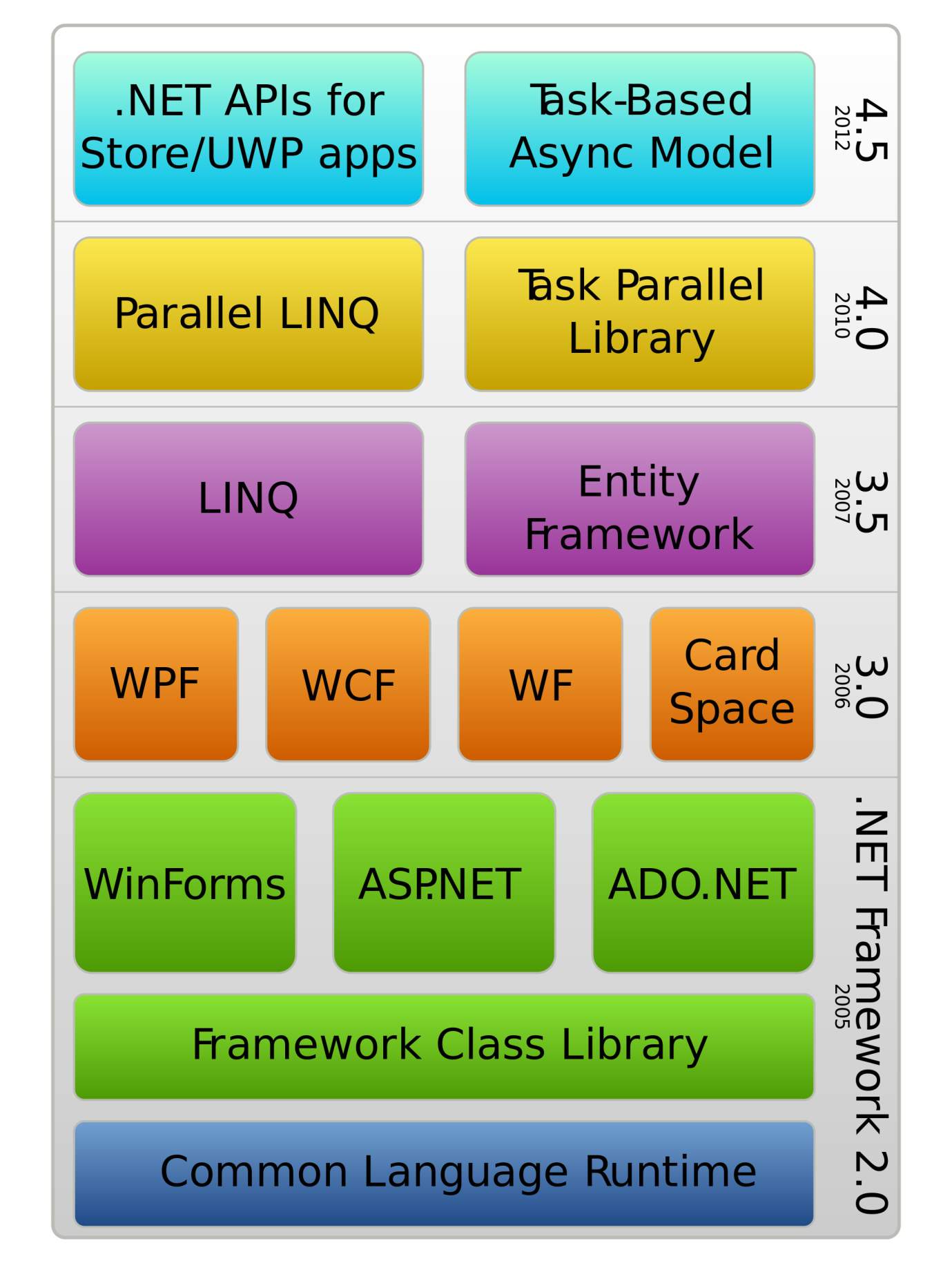
Components of .Net Framework
- Common Language Runtime or CLR
- .Net Framework Class Library
- Common Language Specification
- Common Type System
- Metadata and Assemblies
- Windows Forms
- ASP.NET and ASP.NET AJAX
- ADO.NET
- Windows Workflow Foundation (WF)
- Windows Presentation Foundation
- Windows Communication Foundation (WCF)
- Windows CardSpace
- LINQ
Advantages of .NET Framework
The functionality that the .NET Class Library provides is available to all .NET languages resulting in a consistent object model regardless of the programming language the developer uses.
Direct Support for Security:
Developing an application that resides on a local machine and uses local resources is easy. In this scenario, security isn’t an issue as all the resources are available and accessed locally. Consider an application that accesses data on a remote machine or has to perform a privileged task on behalf of a non-privileged user. In this scenario security is much more important as the application is accessing data from a remote machine.
With .NET, the Framework enables the developer and the system administrator to specify method level security. It uses industry-standard protocols such as TCP/IP, XML, SOAP and HTTP to facilitate distributed application communications. This makes distributed computing more secure because .NET developers cooperate with network security devices instead of working around their security limitations.
Simplified Development Efforts:
Let’s take a look at this with Web applications. With classic ASP, when a developer needs to present data from a database in a Web page, he is required to write the application logic (code) and presentation logic (design) in the same file. He was required to mix the ASP code with the HTML code to get the desired result.
ASP.NET and the .NET Framework simplify development by separating the application logic and presentation logic making it easier to maintain the code. You write the design code (presentation logic) and the actual code (application logic) separately eliminating the need to mix HTML code with ASP code. ASP.NET can also handle the details of maintaining the state of the controls, such as contents in a textbox, between calls to the same ASP.NET page.
Another advantage of creating applications is debugging. Visual Studio .NET and other third party providers provide several debugging tools that simplify application development. The .NET Framework simplifies debugging with support for Runtime diagnostics. Runtime diagnostics helps you to track down bugs and also helps you to determine how well an application performs. The .NET Framework provides three types of Runtime diagnostics: Event Logging, Performance Counters and Tracing.
Easy Application Deployment and Maintenance:
The .NET Framework makes it easy to deploy applications. In the most common form, to install an application, all you need to do is copy the application along with the components it requires into a directory on the target computer. The .NET Framework handles the details of locating and loading the components an application needs, even if several versions of the same application exist on the target computer. The .NET Framework ensures that all the components the application depends on are available on the computer before the application begins to execute
2.1.2 Visual Studio

Microsoft Visual Studio is an integrated development environment (IDE) from Microsoft. It is used to develop computer programs for Microsoft Windows, as well as web sites, web applications and web services. Visual Studio uses Microsoft software development platforms such as Windows API, Windows Forms, Windows Presentation Foundation, Windows Store and Microsoft Silverlight. It can produce both native code and managed code.
Visual Studio includes a code editor supporting IntelliSense (the code completion component) as well as code refactoring. The integrated debugger works both as a source-level debugger and a machine-level debugger. Other built-in tools include a forms designer for building GUI applications, web designer, class designer, and database schema designer. It accepts plug-ins that enhance the functionality at almost every level including adding support for source-control systems and adding new toolsets like editors and visual designers for domain-specific languages or toolsets for other aspects of the software development lifecycle.
Visual Studio supports different programming languages and allows the code editor and debugger to support nearly any programming language, provided a language-specific service exists. Built-in languages include C, C++and C++/CLI (via Visual C++),VB.NET (via Visual Basic .NET), C# (via Visual C#), and F# (as of Visual Studio 2010). Support for other languages such as Python, Ruby, Node.js, and M among others is available via language services installed separately. It also supports XML/XSLT, HTML/XHTML, JavaScript and CSS. Java (and J#) were supported in the past.
Advantages of Visual Studio
- Code available anywhere an internet connection is available
- Simple sharing mechanisms
- Simplified build mechanism
- Many modern IDE features available (Autocomplete, syntax highlighting, etc…)
- Requires a modern browser
3. ABOUT THE SYSTEM
3.1 Overall Description
3.1.1 Goals and Scenarios
Goal-1: System provides user to register and login through his unit number.
- User can register and login through unit number by just providing their correct unit number, block number and password.
- User can register and login only with his correct unit number and block number.
Goal-2: System has a user-friendly user interface.
- A particular user of the system will notify the notices, announcements and posts on the display.
- User will be able to view the feeds from multiple profiles in a cascading manner.
Goal-3: System will allow the user to set post and share photo gallery related to society events.
- User searches other society members profiles and set them as favorites for quick viewing based on their own Interests.
- User can also set the time duration of how old posts he/she wants to view.
Goal-4: System will provide the users with their unique user_id.
- System will maintain the cached data on the user’s device.
- User can retrieve his data anytime in case he logout the application & wants to re-login it.
- The server will maintain the log for User’s preferences which can be retrieved anytime merely by logging in the portal through the user_id.
3.1.2 Reliability
- The System will have to be very reliable due to importance of data and the damages incorrect or incomplete data can do.
3.1.3 Availability
- The System will be available 100% for the users.
- The users will have a social interactions involving sharing, feedback and search for any profiles or their friends 24*7 i.e. the system will be operational 24 hours a day and 7 days a week.
3.1.4 User Requirements
- The system will be designed to be user friendly.
- User should have to register and login to use the system.
- User should be able to navigate the system without any difficulty.
- User should be able to set favorites according to their choices.
- User can give the feedback, complain and share with other society members.
3.1.5 Functional Requirements
In software engineering (and systems engineering), a functional requirement defines a function of a system and its components. A function is described as a set of inputs, the behavior, and outputs.
- The system shall provide feeds from the social accounts the user has logged in from.
- The system shall display the latest feeds & updates from the user specified time period.
- The system shall prompt the user with notification from admin side.
- The system shall provide quick solution of user’s complains.
- The system enables the admin to review, create, edit and delete the profile descriptions set up by various app users.
3.1.6 Non-Functional Requirements
In systems engineering and requirements engineering, a non-functional requirement is a requirement that specifies criteria that can be used to judge the operation of a system, rather than specific behaviors.
- Performance:
- Response times: The portal is very quick. It just takes seconds of time to load the first screen.
- Processing times: It takes about maximum half a minute for fetching data.
- Expandability- needs to be future proof or upgradable.
- Capacity and Scalability:
- Throughput: Any number of times user can capture as many photos as required.
- Growth Requirements: Portal will be popular and will be available for maximum housing areas.
- Backup: Provision for data backup.
- Efficiency:
- The portal must provide easy and fast access without consuming cost.
- There should be sufficient network bandwidth.
- Maintainability- easy to maintain.
- Usability by target user community- Easy to use.
- Reliability:
- User should never be surprised by the behavior of the portal and it’s easy to use to stored data and accessing the data.
- Safety- should be safe to use.
3.2 Feasibility Study
Feasibility is the measure of practical extent to which a project can be carried out successfully. To evaluate feasibility, a feasibility study is performed, which determines whether the solution considered to accomplish the requirements is practical and executable in the software or not. Such information as resource availability, cost estimate for software development, benefits of the software to organization, and cost to be incurred on its maintenance are considered.
The objective of the feasibility study is to establish the reasons for developing software that is acceptable to users and adaptable to change.
We have considered the feasibility check for the various aspects of the project as below.
Feasibility is measured throughout the life cycle. Also, the scope and complexity of an apparently feasible project can change after the initial problems and opportunities are fully analyzed or after the system has been designed.
3.2.1 Technical Feasibility
- Technical feasibility is a measure of the practicality of a specific technical solution and the availability of technical resources and expertise.
- Is the proposed technology or solution practical? Is the technology mature?
- Do we currently possess the necessary technology?
- Do we possess the necessary technical expertise, and is the schedule reasonable?
In case of our application, the system can be updated when we integrate new functionality with new technology.
Current Android software version that is available and already being used by vast smartphone user community is reliable for us to implement the application.
3.2.2 Operational Feasibility
Operational feasibility is a measure of how well a specific solution will work in the organization. It is also a measure of how people feel about the system/project.
- Does management support the system?
- How do the end-users feel about their role in the new system?
- What end-users or managers may resist or not use the system? Can this problem be overcome? If so, how?
- Usability analysis
- Ease of use, Ease of learning, User satisfaction
3.2.3 Economic Feasibility
Economic feasibility is a measure of the cost-effectiveness of a project or solution. This is often called a cost-benefit analysis.
This assesses the positive financial benefits to the authority through this app.
Some of the questions that this section will answer are:
- Is the system cost effective?
- Do benefits outweigh costs?
- The cost of doing full system study
- The cost of business employee time
- Estimated cost of hardware
- Estimated cost of software/software development
- Is the project possible, given the resource constraints?
- What are the savings that will result from the system?
3.2.4 Schedule Feasibility
Schedule feasibility is a measure of how reasonable the project timetable is.
- Can the project really be completed in the given period of time?
The development of this application is part of the IDP University Project. Based on the workforce of our project members, the flow of this application will follow the scheduling plan estimated during the Analysis phase of the software development life cycle.
3.3 Project Planning
3.3.1 Project Development Approach
Spiral Development Approach
As a result of planning and risk analysis, different projects may choose different processes. That is, the spiral model is actually a risk-driven process model generator, in which different risk patterns can lead to choosing incremental, waterfall, evolutionary prototyping, or other subsets of the process elements in the spiral model diagram.
To begin with, a simple overview definition to capture the essence of the model:
The spiral development model is a risk-driven process model generator. It is used to guide multi-stakeholder concurrent engineering of software intensive systems. It has two main distinguishing features. One is a cyclic approach for incrementally growing a system’s degree of definition and implementation while decreasing its degree of risk. The other is a set of anchor point milestones for ensuring stakeholder commitment to feasible and mutually satisfactory system solutions.
A process model answers two main questions:
- What should be done next?
- For how long should it continue?
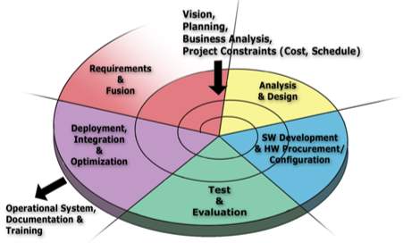
Software Development Life Cycle by implementing Spiral Development Model
Planning Phase: Requirements are gathered during the planning phase. Requirements like ‘BRS’ that is ‘Business Requirement Specifications’ and ‘SRS’ that is ‘System Requirement specifications’. This phase involves pre-defining the functional and non-functional requirements of the program/project and thus the system in itself.
Risk Analysis: In the risk analysis phase, a process is undertaken to identify risk and alternate solutions. A prototype is produced at the end of the risk analysis phase. If any risk is found during the risk analysis then alternate solutions are suggested and implemented.
Engineering Phase: In this phase software is developed, the coding for program logic and the UI is generated along with its testing at the end of the phase.
Evaluation phase: This phase allows the customer as well as the programmers/project team to evaluate the output of the project to date before the project continues to the next spiral. The project successfully exhibiting as well as executing according to the required functionalities is finally deployed to the market.
Advantages of Spiral model:
- High amount of risk analysis hence, avoidance of Risk is enhanced.
- Good for large and mission-critical projects.
- Can accommodate complex requirements from users & customers.
- Highly recommended when the users, especially, are unsure of their needs or could be expecting additional functionalities later.
- Additional Functionality can be added at a later date.
- Strong approval and documentation control.
- Software is produced early in the software life cycle.
3.3.2 Project Plan
Project Planning is an aspect of Project Management that focuses a lot on Project Integration. The project plan reflects the current status of all project activities and is used to monitor and control the project.
The Project Planning tasks ensure that various elements of the Project are coordinated and therefore guide the project execution.
Project Planning helps in:
- Facilitating communication,
- Monitoring/measuring the project progress, and
- Provides overall documentation of assumptions/planning decisions.
The Project Planning Phases can be broadly classified as follows:
- Development of the Project Plan
- Execution of the Project Plan
- Change Control and Corrective Actions
The core attributes that arise in question during the requirement specification compilation are these:
Duration: How long will it take to complete the development?
- It is necessary to understand user’s requirements in details, do a detailed research of what combination of technologies would be best for the project, get acclimatized to them, do the rest of the planning and go ahead with the work. The difficult task would be to study the working of the different social networks & to aggregate their feeds into our code. As per the requirements our team will be working with the different APIs to gain maximum knowledge. Hence the duration of the Project can be roughly estimated to 8 months.
Efforts: How much efforts would be required?
- Since it is mobile application developed with new ideas it require lot of efforts of human hours to gain maximum output. Thus efforts can be estimated to 13 hours of weekdays work for 8 months.
3.3.3 Implementation Strategies:
3.3.3.1 Business Model Canvas:
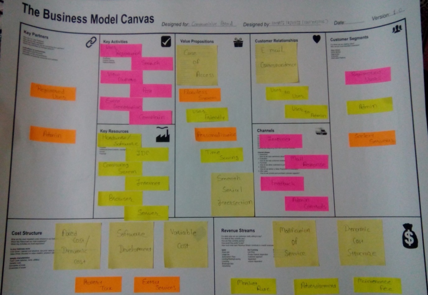
1. Customer Segments:
Various sets of customers can be segmented based on the different needs and attributes to ensure appropriate services of our system. The different types of customer segments include
- Society members
- Admin
- Other society workers
- Society Servants
2. Value Proposition:
The collection of products and services a business offers to meet the needs of its customers information. when any user search for any cottage than proper information is given by web application this is main aim of value proposition.
The value proposition provides value through various elements such as best offers, User_friendly, design, brand/status, price, cost reduction, accessibility, and convenience/usability.
- Case Of access
- Flawless System
- User friendly
- Personalization
- Time saving
- Smooth serial intersection
3. Channels:
A company can deliver its value proposition to its targeted customers through different channels. Effective channels will distribute a company’s value proposition in ways that are fast, efficient and cost effective. An organization can reach its clients either owner or broker, or a combination of both.
- Internet
- Mail Response
- Feedback
- Admin Controls
4. Customer Relationships:
To ensure the survival and success of any businesses, companies must identify the type of relationship they want to create with their customer segments. Various forms of customer relationships include:
- Personal Assistance(E-Mail Correspondence)
- Society member to Society member
- Society member to Admin
- Society member to Event manager
5. Revenue Streams:
The way a company makes income from each customer segment. Several ways to generate a revenue stream:
- Maintenance fee
- Dynamic cost structure
- Modification of Services
- Market Rate
- Advertisement
6. Key Activities:
The most important activities in executing a company’s value proposition. Key Activities contain all the activities which are works in your application
- User registration
- Search
- View Gallery
- Post
- Event Generation
- Complain
7. Key Resource:
The resources that are necessary to create value for the customer. They are considered an asset to a company, which are needed in order to sustain and support the business. These resources could be human, financial, physical and intellectual.
- Hardware/Software
- Internet Development Environment
- Computing System
- Internet
- Browser
- Server
- Database
8. Key Partners:
In order to optimize operations and reduce risks of a business model, organization usually develop buyer-supplier relationships so they can focus on their core activity.
- Registered Users
- Admin
9. Cost Structure:
This describes the different cost of different property and additional services. Like when broker is between owner and renter then extra cost is add for broker.
Classes of Business Structures:
- Software development
- Internet cost
- Fixed Costs / Dynamic Costs
- Variable cost
- Property Tax
- Extra Service
4. ANALYSIS & DESIGN
4.1 Analysis
Development of system requires analysis of the process to be digitized in order to enable a correct system, a system that functions as required and to assist the potential users of the system understand the general functionality of the system. The analysis specifies the system’s objectives and constraints to which designers have to comply. The purpose of doing analysis is to transform the system’s major inputs into structured specification.
4.1.1 Design Methodology
Design methods is a broad area that focuses on:
- Divergence – Exploring possibilities and constraints of inherited situations by applying critical thinking through qualitative and quantitative research methods to create new understanding (problem space) toward better design solutions.
- Transformation – Redefining specifications of design solutions which can lead to better guidelines for traditional and contemporary design activities (architecture, graphic, industrial, information, interaction, et al.) and/or multidisciplinary response.
- Convergence – Prototyping possible scenarios for better design solutions that incrementally or significantly improve the originally inherited situation.
- Sustainability – Managing the process of exploring, redefining and prototyping of design solutions continually over time.
- Articulation – the visual relationship between the parts and the whole.
In applying the spiral approach to our project, we have to consider the most integral possibilities when focusing on the application design modules. Since the SDLC is Spiral Model, we can improve the design, shall the need arise, periodically.
4.2 Design
4.2.1 Data Flow Diagram
DFD Level 0:
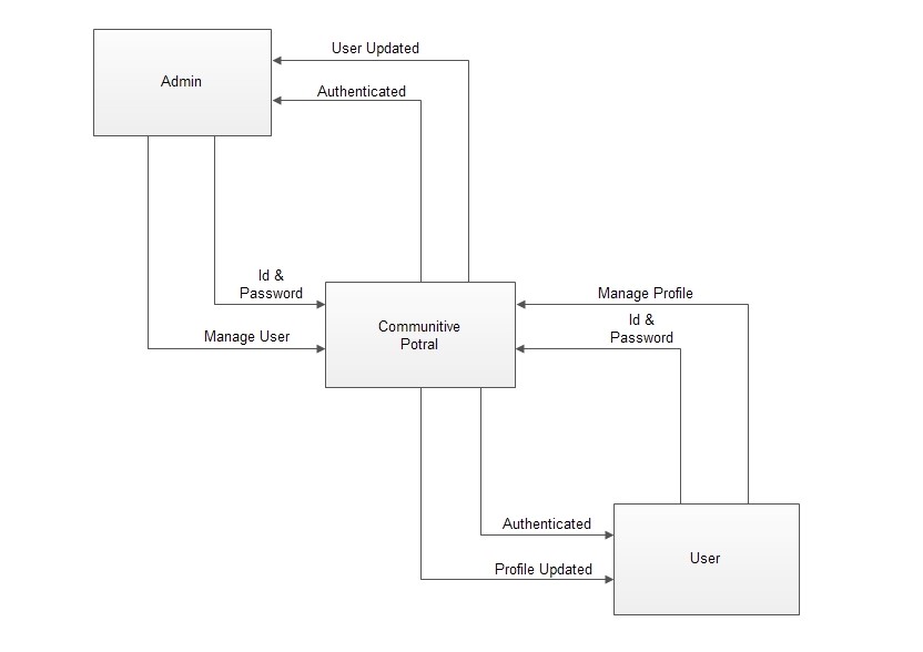
(Figure 4.2.1.1)
DFD Level 1:
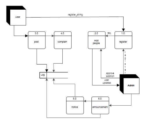
(Figure 4.2.1.2)
4.2.2 Use Case Diagram
Use Case Diagram-1:
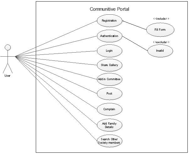
(Figure 4.2.2.1)
Use Case Diagram-2:
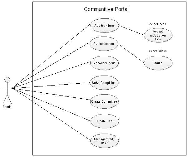
(Figure 4.2.2.2)
Use Case Diagram-3:
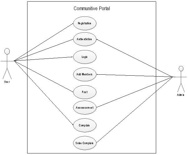
(Figure 4.2.2.3)
4.2.3 Sequence diagram
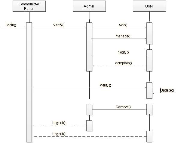
(Figure 4.2.3.1)
4.2.4 Activity Diagram
Activity Diagram 1:
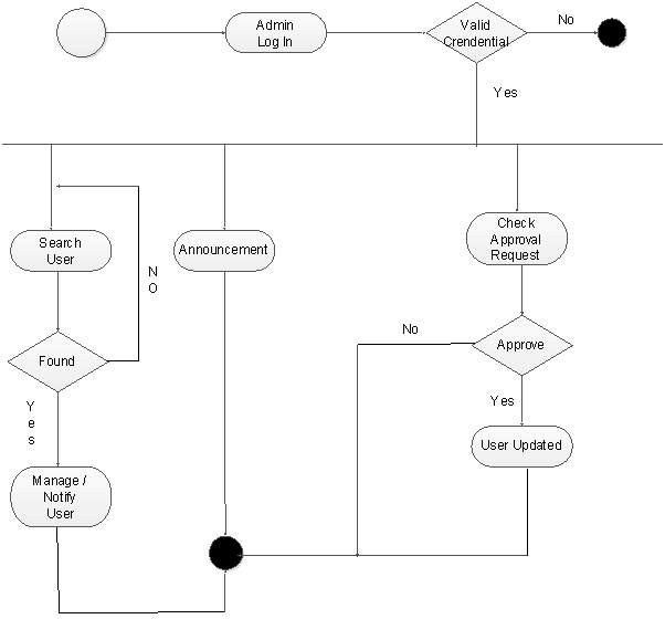
(Figure 4.2.4.1)
Activity Diagram 2:
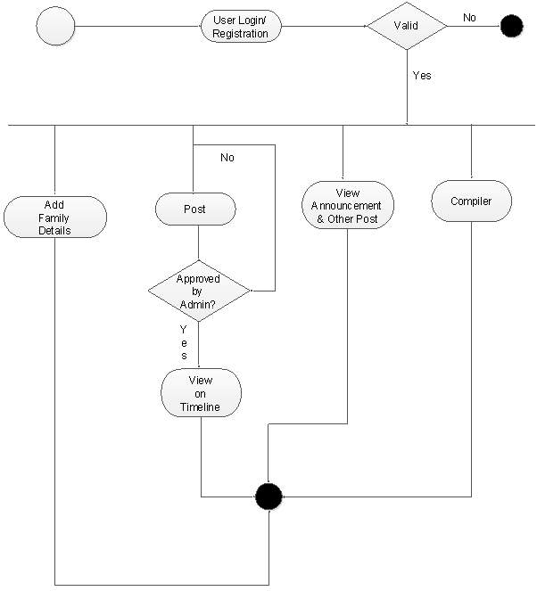
(Figure 4.2.4.2)
4.2.5 Entity-Relationship Diagram
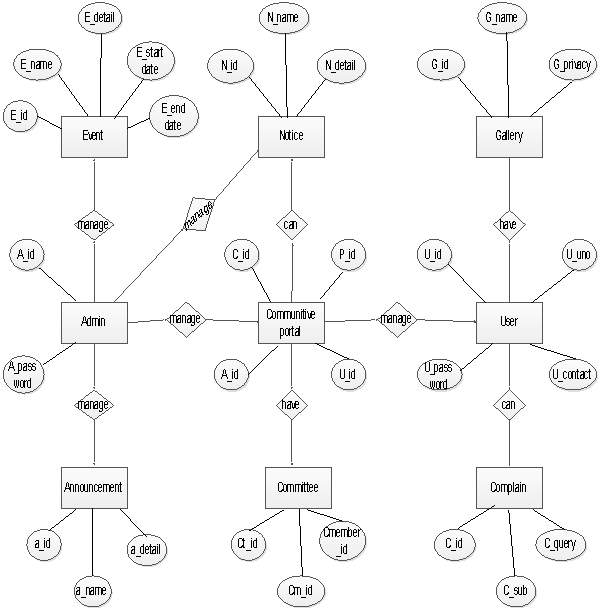
(Figure 4.2.5.1)
4.2.6 Class Diagram
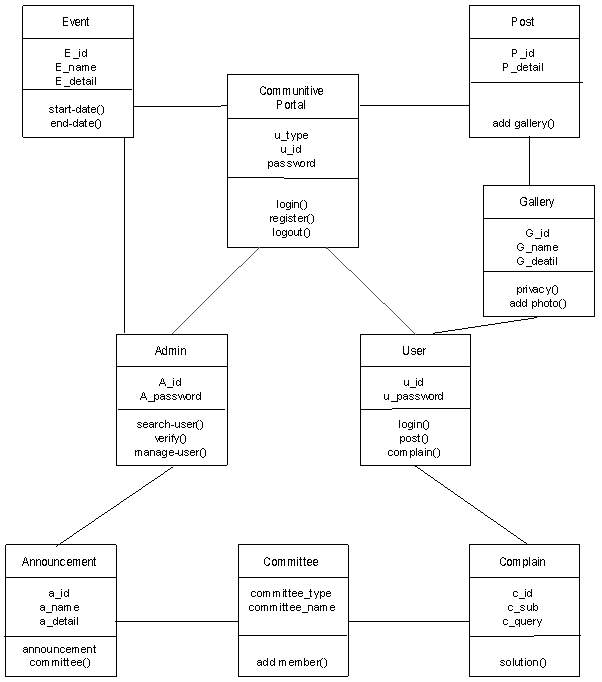
(Figure 4.2.6.1)
4.3 Data Dictionary:
Table No.: 1
Table Name: ADMIN
Primary Key: A_id
Description: The admin will login into the system. It stores Admin name and Password.
| Field | Data Type | Constraints | Description |
| A_id | int | Primary key | Unique Id |
| A_name | nvarchar(64) | Null | Store Admin name |
| A_password | nvarchar(16) | Null | Store password |
Table No.: 2
Table Name: User
Primary Key: U_id
Description: The user will register into the system.
| Field | Data Type | Constraints | Description |
| U_id | int | Primary key | Unique Id |
| U_name | nvarchar(64) | Not null | Store username |
| U_DOB | date-time | Not null | Store dateofbirth |
| U_email | nvarchar(64) | Not null | Store emailed |
| U_gender | nvarchar(16) | Not null | Store gender |
| U_contact | nvarchar(10) | Allow null | Store contact |
| U_hobbies | nvarchar(200) | Allow null | Store hobbies |
| U_occupation | nvarchar(50) | Allow null | Store occupation |
| U_companyname | nvarchar(100) | Allow null | Store companyname |
| U_workaddress | nvarchar(200) | Allow null | Store workaddress |
| U_bloodgroup | nvarchar(16) | Allow null | Store bloodgroup |
| U_persontype | nvarchar(16) | Allow null | Store persontype |
| U_password | nvarchar(16) | Not null | Store password |
Table No.: 3
Table Name: User family member
Primary Key: Fm_id
Description: The user will add his/her family members details into the system.
| Field | Data Type | Constraints | Description |
| Fm_id | int | Primary key | Unique id |
| Fm_name | nvarchar(50) | Allow null | Store name |
| Fm_age | nvarchar(2) | Allow null | Store age |
| Fm_contact | nvarchar(10) | Allow null | Store contact no |
| Fm_occupation | nvarchar(50) | Allow null | Store occupation |
| bit is active | bit | Allow null | Store activestatus |
Table No.: 4
Table Name: Unit master
Primary Key: Unitmaster_id
Description: The user will add his/her unit number & block into the system.
| Field | Data Type | Constraints | Description |
| Unitmaster_id | int | Primary key | Unique id |
| Block | nvarchar(50) | Not null | Store block |
| Flat_no | nvarchar(50) | Not null | Store flat no |
| datecreated | date-time | – | Store time |
| bit is active | bit | Allow null | Store activestatus |
Table No.: 5
Table Name: Unit detail
Primary Key: Unitdtl_id
Description: The user will log in into the system.
| Field | Data Type | Constraints | Description |
| Unitdtl_id | int | Primary key | Unique id |
| Unitmaster_id | int | Foreign Key | Store unitmaster id |
| Password | nvarchar(10) | Not null | Store password |
Table No.: 6
Table Name: Post
Primary Key: P_id
Description: The user will post into the system.
| Field | Data Type | Constraints | Description |
| P_id | int | Primary key | Unique id |
| P_title | Nvarchar(50) | Allow null | Store title |
| P_detail | Nvarchar(MAX) | Allow null | Store detail |
| P_datecreated | Date-time | – | Store time |
| bit is active | bit | Allow null | Store activestatus |
Table No.: 7
Table Name: Post Like
Primary Key: Plike_id
Description: The user will like post into the system.
| Field | Data Type | Constraints | Description |
| Plike_id | int | Primary key | Unique id |
| P_id | int | Foreign key | Store post id |
| U_id | Int | Foreign key | Store user id |
| Plike_datecreated | Date-time | – | Store time |
Table No.: 8
Table Name: Post Comment
Primary Key: Pcomment_id
Description: The user will comment on the post into the system.
| Field | Data Type | Constraints | Description |
| Pcomment_id | int | Primary key | Unique id |
| P_id | int | Foreign key | Store post id |
| U_id | int | Foreign key | Store user id |
| Pcomment_text | nvarchar(MAX) | Allow null | Store comment |
| Datecreated | date-time | – | Store time |
| bit is active | bit | Allow null | Store activestatus |
| bit is delete | bit | Allow null | Store deletestatus |
Table No.: 9
Table Name: Notice
Primary Key: N_id
Description: The admin will add notice into the system.
| Field | Data Type | Constraints | Description |
| N_id | int | Primary key | Unique id |
| A_id | int | Foreign key | Store adminid |
| N_number | nvarchar(16) | Not null | Store number |
| N_name | nvarchar(50) | Allow null | Store name |
| N_subject | nvarhar(MAX) | Allow null | Store subject |
| N_detail | nvarchar(MAX) | Allow null | Store detail |
| N_datecreated | date-time | – | Store time |
| Bit is active | bit | Allow null | Store activestatus |
Table No.: 10
Table Name: Complain
Primary Key: C_id
Description: The user will add complain into the system.
| Field | Data Type | Constraints | Description |
| C_id | int | Primary key | Unique id |
| U_id | int | Foreign key | Store userid |
| C_subject | nvarchar(MAX) | Not null | Store subject |
| C_query | nvarchar(MAX) | Not null | Store query |
| C_datecreated | date-time | – | Store time |
| Bit is active | bit | Allow null | Store activestatus |
Table No.: 11
Table Name: Committee type
Primary Key: Ct_id
Description: The admin will create different committee types into the system.
| Field | Data Type | Constraints | Description |
| Ct_id | int | Primary key | Unique id |
| A_id | int | Foreign key | Store adminid |
| Ct_name | nvarchar(50) | Not null | Store name |
| Ct_datecreated | date-time | – | Store time |
| Bit is active | bit | Allow null | Store activestatus |
Table No.: 12
Table Name: Committee master
Primary Key: Cm_id
Description: The admin will add committee masters for committee types into the system.
| Field | Data Type | Constraints | Description |
| Cm_id | int | Primary key | Unique id |
| Ct_id | int | Foreign key | Store id |
| Cm_name | nvarchar(50) | Not null | Store name |
| Cm_detail | nvarchar(MAX) | Allow null | Store detail |
| Ct_datecreated | date-time | – | Store time |
| Bit is active | bit | Allow null | Store activestatus |
Table No.: 13
Table Name: Committee member
Primary Key: Cmember_id
Description: The admin will add users as committee members for committee types into the system.
| Field | Data Type | Constraints | Description |
| Cmember_id | Int | Primary key | Unique id |
| Cm_id | int | Foreign key | Store mastereid |
| U_id | Int | Foreign key | Store userid |
| Ct_datecreated | date-time | – | Store time |
| Bit is active | bit | Allow null | Store activestatus |
Table No.: 14
Table Name: Event
Primary Key: E_id
Description: The committee master will add event into the system.
| Field | Data Type | Constraints | Description |
| E_id | int | Primary key | Unique id |
| Cm_id | int | Foreign key | Store mastereid |
| E_name | nvarchar(50) | Not null | Store eventname |
| E_detail | nvarchar(MAX) | Allow null | Store eventdetail |
| E_starttime | date-time | – | Store starttime |
| E_endtime | date-time | – | Store endtime |
| G_id | dnt | Foreign key | Store galleryid |
| E_regreq | bit | Allow null | Store reg. request |
| E_reg.enddate | date-time | – | Store reg.enddate |
| E_datecreated | date-time | – | Store time |
| Bit is active | bit | Allow null | Store activestatus |
Table No.: 15
Table Name: Event subscriber
Primary Key: ES_id
Description: The committee master will add users with their request in event into the system.
| Field | Data Type | Constraints | Description |
| ES_id | int | Primary key | Unique id |
| E_id | int | Foreign key | Store event id |
| U_id | int | Foreign key | Store user id |
| ES_datecreated | date-time | – | Store time |
| ES_reg.people | int | Allow null | Store reg.people |
| Bit is active | bit | Allow null | Store activestatus |
Table No.: 16
Table Name: Gallery
Primary Key: G_id
Description: The user will add photo gallery into the system.
| Field | Data Type | Constraints | Description |
| G_id | int | Primary key | Unique id |
| U_id | int | Foreign key | Store user id |
| G_name | nvarchar(50) | Allow null | Store galleryname |
| G_detail | nvarchar(MAX) | Allow null | Store gallerydetail |
| G_privacy | bit | Allow null | Store privacy |
| G_datecreated | date-time | – | Store time |
| Bit is active | bit | Allow null | Store activestatus |
Table No.: 17
Table Name: Gallery image
Primary Key: GI_id
Description: The user will add images in different gallerys into the system.
| Field | Data Type | Constraints | Description |
| GI_id | int | Primary key | Unique id |
| G_id | int | Foreign key | Store gallery id |
| GI_image | big int | Allow null | Store image |
| GI_detail | nvarchar(200) | Allow null | Store imagedetail |
| GI_datecreated | date-time | – | Store time |
| Bit is active | bit | Allow null | Store activestatus |
Table No.: 18
Table Name: Announcement
Primary Key: A_id
Description: The admin will add announcement into the system.
| Field | Data Type | Constraints | Description |
| A_id | int | Primary key | Unique id |
| U_id | int | Foreign key | Store userid |
| A_name | nvarchar(50) | Not null | Store name |
| A_detail | nvarchar(MAX) | Not null | Store detail |
| A_datecreated | date-time | – | Store time |
| Bit is active | bit | Allow null | Store activestatus |
| Bit is delete | bit | Allow null | Store deletestatus |
Table No.: 19
Table Name: Announcement committee
Primary Key: AC_id
Description: The admin will add members in announcement committee into the system.
| Field | Data Type | Constraints | Description |
| AC_id | int | Primary key | Unique id |
| U_id | int | Foreign key | Store userid |
| Cm_id | int | Foreign key | Store mastereid |
| AC_name | nvarchar(50) | Not null | Store name |
| AC_detail | nvarchar(MAX) | Not null | Store detail |
| AC_datecreated | date-time | – | Store time |
| Bit is active | bit | Allow null | Store activestatus |
| Bit is delete | bit | Allow null | Store deletestatus |
Table No.: 20
Table Name: Announcement like
Primary Key: AL_id
Description: The user will like announcement into the system.
| Field | Data Type | Constraints | Description |
| AL_id | int | Primary key | Unique id |
| A_id | int | Foreign key | Store id |
| U_id | int | Foreign key | Store userid |
| AL_datecreated | date-time | – | Store time |
| Bit is active | bit | Allow null | Store activestatus |
| Bit is delete | bit | Allow null | Store deletestatus |
Table No.: 21
Table Name: Announcement comment
Primary Key: Acomment_id
Description: The user will add comment on announcement into the system.
| Field | Data Type | Constraints | Description |
| Acomment_id | int | Primary key | Unique id |
| A_id | int | Foreign key | Store id |
| U_id | int | Foreign key | Store userid |
| Acomment_id | nvarchar(MAX) | Not null | Store comment |
| Acomment_datecreated | date-time | – | Store time |
| Bit is active | bit | Allow null | Store activestatus |
| Bit is delete | bit | Allow null | Store deletestatus |
5. IMPLEMENTATION & TESTING
5.1 IMPLEMENTATION
Challenges identified for successful design and implementation of this project are dominated by: complexity, reliability/availability, transparent data access while respecting security.
The project was a result of a group coordination. The team was having three members. The team was guided by internal guide. The team structure depends on the management style of the organization, the number of people in the team, their skill levels and the problem difficulty.
This web application is basically for communication system in the society by the user and managing the objects by the admin and also it is time saving. There is well-structured menu and icon has been provided for user. User can easily work through this system. It has user friendly interface.
Here are some Snapshots of Portal as following:
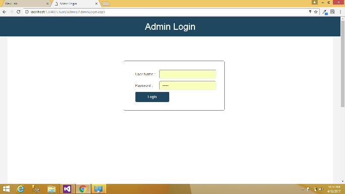
Admin Login
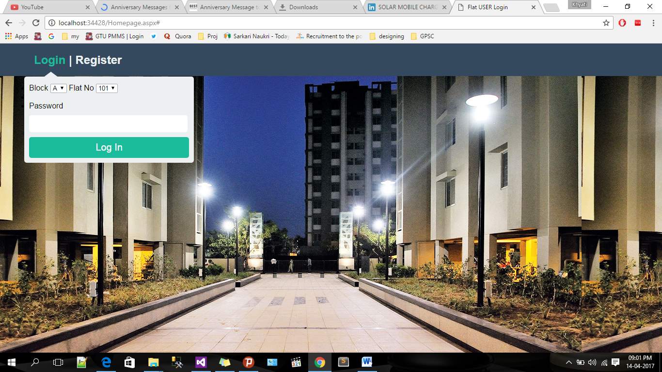
User Login
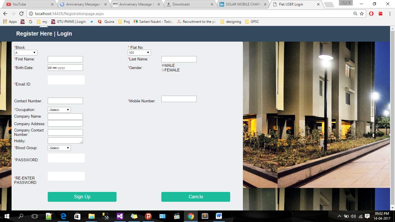
Registration Page
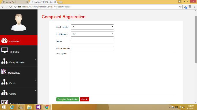
Complain Box Page
5.2 TESTING
5.2.1 System Testing
System testing of software or hardware is testing conducted on a complete, integrated system to evaluate the system’s compliance with its specified requirements. System testing falls within the scope of black box testing, and as such, should require no knowledge of the inner design of the code or logic.
Some of the Testing Objectives are:-
- Testing is a process of executing a program with the intent of finding the errors.
- A good test case is one that has a high probability of finding undiscovered errors.
- A successful Test on the other hand is one that uncovers all the undiscovered errors.
5.2.2 Testing Strategy
Black box testing
The technique of testing without having any knowledge of the interior workings of the application is Black Box testing. The tester is oblivious to the system architecture and does not have access to the source code. Typically, when performing a black box test, a tester will interact with the system’s user interface by providing inputs and examining outputs without knowing how and where the inputs are worked upon.
White box testing
White box testing is the detailed investigation of internal logic and structure of the code. White box testing is also called glass testing or open box testing. In order to perform white box testing on an application, the tester needs to possess knowledge of the internal working of the code. The tester needs to have a look inside the source code and find out which unit/chunk of the code is behaving inappropriately.
Grey box testing
Grey Box testing is a technique to test the application with limited knowledge of the internal workings of an application. In software testing, the term the more you know the better carries a lot of weight when testing an application.
5.2.3 Testing Methods
Testing is a set of activities that can be planned in advance and conducted systematically to carry out the testing procedures of the proposed system. Testing generally done at two levels- testing of individual, modules and testing of the entire ensure that the software does not fail, that it will run according to its specifications and in the way users expect.
Following procedures will be carried out:
- Unit Testing or Component Testing
- Integration testing
- System Testing or End-to-End Testing
- Acceptance Testing
- Functional Testing
- Security Testing
5.2.3.1 Unit Testing or Component Testing
It is the first and the most basic level of Software Testing, in which a single unit (i.e. a smallest testable part of a software) is examined in isolation from the remaining source code. Unit Testing is done to verify whether a unit is functioning properly. In other words, it checks the smallest units of code and proves that the particular unit can work perfectly in isolation. However, one needs to make sure that when these units are combined, they work in a cohesive manner. This directs us to other levels of software testing.
5.2.3.2 Integration Testing
After Unit Testing, software components are clubbed together in large aggregates and tested, to verify the proper functioning, performance and reliability between units, and expose any defect in the interface. This process is known as Integration Testing. It can be performed in the following way:
Incremental Testing
Testing in the traditional and structured way, this classic approach follows a hierarchical path. It can further be divided into two types:
Top-Down Testing:
In this approach, top level integrated units are tested first, followed by step by step examination of lower level modules.
Bottom-Up Testing:
In contrast to the top-down approach, this method facilitates testing at the lower level first, and then taking it up the hierarchy. It is generally practiced where bottom-up development process is followed.
5.2.3.3 System Testing or End-to-End Testing
After identifying functional bugs at the Unit and Integration testing level, System Testing is done to scrutinize the entire software system. The objective of this test is to verify the non-functional part of the software like speed, security, reliability and accuracy. Evaluation of external interfaces like applications, hardware devices, etc. is also done at this time. System Testing is also done to ensure that the software meets the customer’s functional and business requirements.
5.2.3.4 Acceptance Testing
This test is conducted to determine that the software system complies with the customer’s requirements and is ready to be delivered to them. Every feature is checked from the user’s perspective by the testing team and the feature is marked accepted or rejected. The results of these tests are very subjective in nature and it takes a while to figure out the exact issue in the code.
5.2.3.5 Functional Testing
Also known as Conformance Testing or Correctness Testing, this test is used to validate whether a particular function is as per the specifications or not. The recorded results answer ―can the user do this or ―does this particular feature work.
5.2.3.6 Security Testing
This test is required to look for any loopholes in the security mechanism of the software system for complete protection and functionality of data. It includes elements of integrity, confidentiality, availability, non-repudiation, authorization and authentication.
5.3 TEST CASES
The test cases are designed to check the system functionality to ensure application quality. Here we have designed test cases, which are directly derived from the system scenarios from the analysis phase. These scenarios are developed to identify events and actions in the system. They assist here for test case development because they are sequence of interaction between system and user.
6. CONCLUSION & FUTURE WORK
6.1 Conclusion
This report specifies the documentation of Communitive Portal Web Application. This web portal will exclusively develop by and for the private use for use of some residential society , with a view to use this website as a common platform for developing centralized databank , sharing common announcements , complaints , suggestions and make use of databank for the internal individual liasoning purpose.
By implementing this system, it will be easy to get connected with other society members and updated with the society issues and events As there is a major part of public which believe that their online presence over social media is as important as their real life, this portal will prove a subtle solution to their needs.
Thus, it can be concluded that this project has aspiration to be a user friendly Web application once it is all developed and deployed with hope that its functionalities fulfill the standards expected by the users.
6.2 Future Work
Based on the user’s feedback, we will improve our system with any additional functionalities, shall the need arise. We are obligated to provide the best of functionalities & seamless user experience that will evolve with the existing social media platforms as well. We are hopeful of positive response for this first of many efforts.
Appendix I: BIBLIOGRAPHY
Books:
Oriented Modelling and Design with UML second edition by Michael Blaha and James Rambaugh
Pressman R.S., Software Engineering: A Practitioner’s Approach, 5th Edition TMH
References:
.NET - http://source.NET.com/
Wikipedia - https://en.wikipedia.org/
Visual Studio – Introduction http://developer.Visualstudioultimate2012.com/guides/cross-platform/getting_started/introducing_visual_studio/
Google Images
http://plagiarisma.net/
Cite This Work
To export a reference to this article please select a referencing stye below:
Related Services
View all


Related Content
All TagsContent relating to: "Community Development"
Community development is defined by the UN as "a process where community members come together to take collective action and generate solutions to common problems".
Related Articles

DMCA / Removal Request
If you are the original writer of this dissertation and no longer wish to have your work published on the UKDiss.com website then please: