Literature Review on a CUK Converter Design
Info: 3671 words (15 pages) Example Literature Review
Published: 20th Aug 2021
Tagged: EngineeringElectronics
Abstract
In recent years, there is a remarkable change and improvement of modern power supply technology because of the advent of power electronics. Meanwhile, many topologies are widely applied in several fields such as computers, communications and electrical vehicles etc. In addition, the renewable energy is playing more and more important role in our life. For instance, the solar photovoltaic source is one of the cleanest energy source and is extensively applied over the world. The application of PV is shown below. For the end of 2016 IRENA reports 2900.98 GWP of globally installed PV capacity, giving clear national specific data for 147 countries. [1]
This literature review briefly gives the description of CUK converter. The comparison between the CUK converter and different converter topologies would be illustrated. In addition, CUK converter has various applications in several different domains and how the non-isolated CUK converter operate with different parameters. Further research are related to different controller strategies.
Index terms - topologies, renewable energy, CUK converter, control strategies
Contents
The topology evolution process of the CUK converter
The principle of operation of CUK converter
The comparitive discussion on CUK and different topologies based on PV system.
The controller strategy of converter
Introduction
DC-DC converters are becoming more and more popular in several domains owning to the advance of semiconductors. Occasionally, the DC-DC converter is termed as DC chopper. One of the functions of DC-DC converter is to provide a demanded output voltage or variable output voltage with a required input voltage. Under this condition, the converter is non-isolated. The isolated converter has the AC part, which means that the input side and the output side are isolated with the transformer. There are a variety of DC/DC different topologies.
One of the common topologies is CUK converter named after its inventor is a combination of the step-up circuit and step-down circuit. There are a couple of advantages of this converter. One advantage is the magnitude of output voltage generated by the CUK converter can be higher or lower than the magnitude of input supply voltage however the polarity of the output voltage is reverse of input voltage. The main dominance of it is to come up with the control of large amount of power with simplified configurations and less electronics components. Moreover, under the condition of multiplex output converter, the ripple current of one specific output port is zero with the decline of input voltage. In the other words, for the harmonics of operation of switching devices, it is dispensable to have the EMI filtering. Furthermore, in the output side, there is no need to have the filter capacitor to reduce the output ripple.
According to the above information, CUK converter is named after Slobodan Ćuk of the California Institute of Technology, who first presented the design [2]. Several published papers related to the CUK converter topologies is upgraded to adjust to different applications. In this review, the basic operation of the CUK converter and the analysis of CUK converter with different parameters such as output voltage, input voltage, PWM signal and frequency etc. In addition, the contrast between CUK converter and different DC-DC converters and a variety of applications of CUK converter would be presented below.
Problems statement
To have a better understanding of project topic, it is necessary to go through the operation and the characteristic of the CUK converter. Based on typical characteristic compared with diverse converters, CUK converter have a better selected application. To have a great performance in this application, various control strategies are supposed to be used to meet the requirement of the application. Moreover, it is significant to have a determination of control strategy.
Literature review
The topology evolution process of the CUK converter
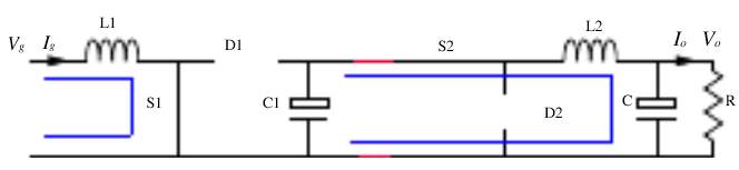
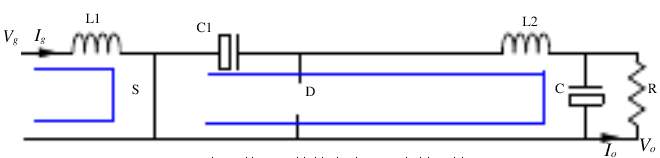
It is well known that the CUK converter is a combination of BUCK chopper and BOOST chopper. Firstly, the BUCK converter and the BOOST converter were made as cascade connection which is shown in fig.1. After that, with the similar driving signal applied to two active switches, the equivalent circuit of the period when the switch is on and the period when the switch is off need to be simplified. That is the components of the cascade connection would be less which means the number of active and passive switches is reduced to one. More over the new circuit working principle is exactly similar with a cascade converter. What’s more, the topology of the new circuit is simpler than the previous one. The evolution process of CUK converter has been shown in the fig.2
[3]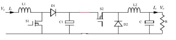
Figure1: The boost converter and buck converter cascade
 |
 |
 |
 |
Two states of two equivalent circuits with single active and passive switch
Two states of two equivalent circuits of a cascade converter
Figure 2
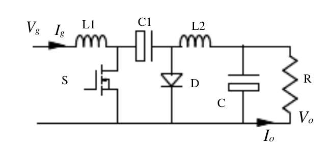
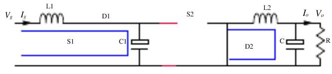
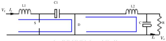
Figure 3: Basic CUK converter
The principle of operation of CUK converter
The basic CUK converter can be inspected in the fig.4. If the VC and VCO polarities are in the reverse direction of the loop considered and the current must increase, the current must actually increase in the opposite direction of the assumed direction [4].
Figure 4: CUK converter with MOSFET
Interval 1: Mode 1 shows when the switch S is turned on, the equivalent circuit has been shown in fig.5. In this mode, the source Vs charge the inductor as a result, the current through the inductor L rises. The current through Vs, L, S forms a current loop. Meanwhile, since VC>VO, the capacitor C discharge and the diode D has the inverse voltage which is regarded as open circuit. The energy stored in the capacitor was transferred to capacitor Co and load and inductor Lo. In the other words, the voltage of capacitor Co increases and the current of inductor rises. The current through C, S, load, Loforms another current loop. [4]
Vs=VL
(1)
Vs=L*didt
(2)
ΔIL=VS*D*TL
(Current decreases)(3)
For inductor Lo,
VC+VLo+VO=0
(4)
dILodt=-1L*(VC+VO)
(Current decreases)(5)
Figure 5: When the switch S is on (mode 1)
Interval 2: When the switch is off, the equivalent circuit can be inspected in the fig.6. In this mode, the capacitor C is charged by supply voltage and inductor L as the source through the inductor L and diode D. What’s more, because of the Voltage VC>VS, the inductor current decreases. At the same time, the energy stored in the inductor Lo is transferred to the load thereby the current of inductor ILodeclines. As a result, the current through Lo, D, load forms a current loop.
-VS+VC+VL=0
(6)
didt=-(VC-VS)L
(7)
For inductor Lo
VLO-VCO=0
(Current decreases)(8)
dILOdt=VCOL
(Current decreases)(9)
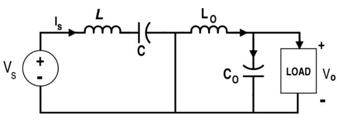
Figure 6: When the switch S is off (Mode 2)
Because the inductor L is the source when the switch is off and the IL decreases therefore didtshoule be positive. It is appearant that the charging time of capacitor C is
1-D*T,
ΔVC=ΔQC=1C∫01-D*TICdt=IS1-D*TC
(10)
IC=IS
(11)
Inspection of the condition of volt-sec balance
VS*D*T=VC-VS*1-D*T
(12)
VC=1(1-D)VS
(13)
VC+VCO*D*T=-VCO*1-D*T)
(14)
VC*D=-VCO
(15)
VCO=-D1-D*VS
(16)
VO=-VCO
as well
VO=D1-D*VS
(17)
Because of the condition of the capacitor C charging balance
IL=IS
(18)
ILO=IO
(19)
The assumption is that there is no loss in this converter
PIN=VS*IS
(20)
Pout=Vo*Io
(21)
VS*IS=D(1-D)*VS*IO
(22)
IS=D1-DIO
(23)
IO=VOR
(24)
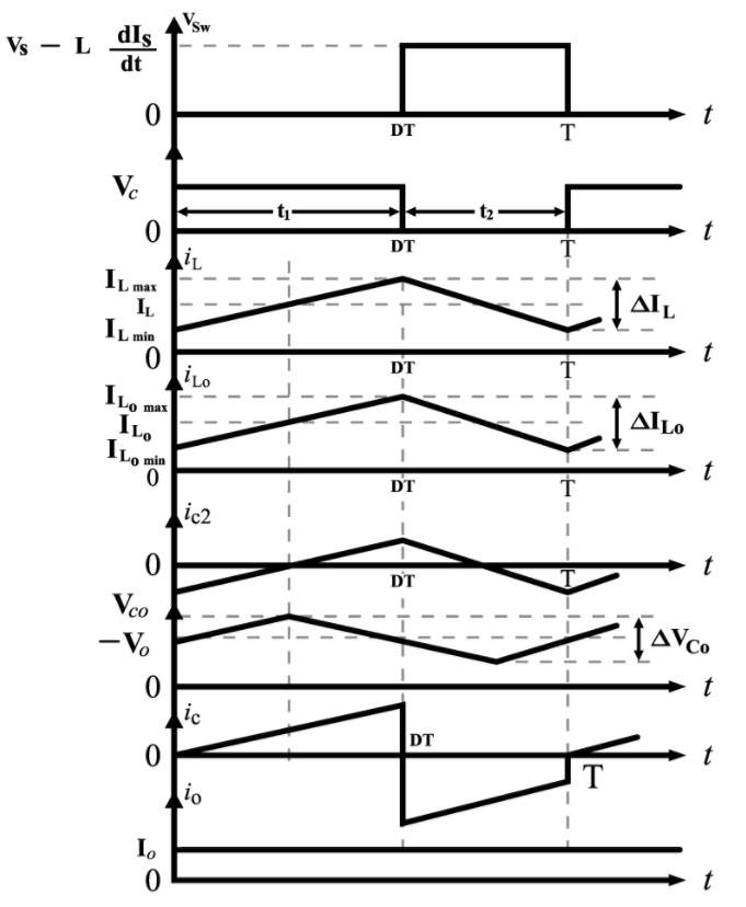
Figure 7: Switch (S) Voltage, Capacitor (C) Voltage, Inductor (L) Current, Inductor (LO) Current, Capacitor (CO) Voltage, Capacitor (C) Current and Load Current respectively for the CUK Converter
Proposed approach
The comparitive discussion on CUK and different topologies based on PV system
The description of PV application, the PV module is a device that the sunlignt energy can be transformed into electrical energy by solar cells. The equivalent circuit of PV is show in fig 8.
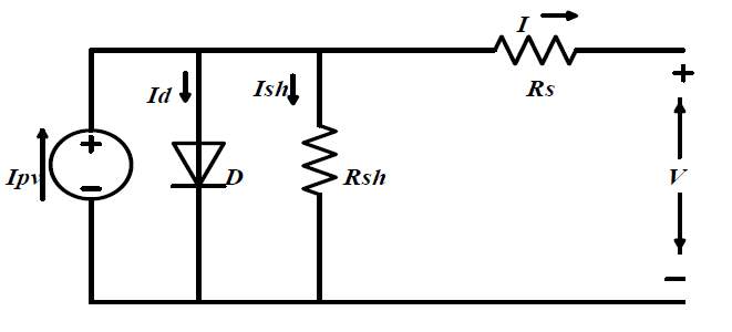
Figure 8: Schematic diagram of single diode solar cell [5]
The
Ipvis the cell photovoltaic current which depends on outside temperature and irradiance. There is a diode paralleling with the source
Ipv. The
Rshand
Rsrespectively represent the cells intrinsic shunt and series resistances. [6]
In terms of the i-v characteristic of operation of PV system, which have been shown in the fig 9 as well as the P-V characteristic of PV system. In the fig 9 there are two different curves depending on different temperature. In addition, the points that the maximum current with zero voltage
Iscand the maximum voltage with zero current
Vocare important. With this curve, the curve of p-v can be plotted easily which has been shown in the fig 10. Referring to this fig 10the maximum point of power
Pmgenerated by the module where the i-v is maximum. There is an equation
Pm=FF*Isc*Voc to represent the relation between voltage current and the maxmiun power. Which means the coefficient fill factor (FF) of the current multiplying voltage plays an important role to determine the quality of the power. Thereby the magnitude of FF been close to 1 will give a better quality of power. [7]
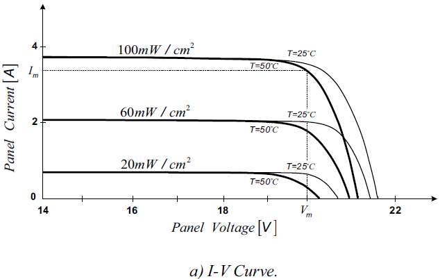
Figure 9: Characteristic curves of a PV module[8]
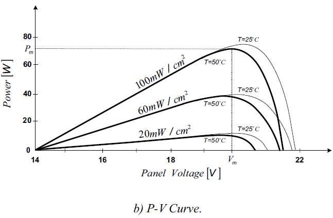
Figure 10: Characteristic curves of a PV module[8]
In terms of the converter of MMPT, the characteristics of the converter are vital to meet the requirement of MPPT application. Here are the characteristics comparison between different converters applied to MPPT techniques. Compared with buck chopper and boost converter, the of CUK converter has the high output voltage level and low output voltage level with fixed input voltage depending on the duty ratio. What’s more, the CUK converter has lower switching loss. Referring to the table (1), the efficiency of CUK converter is higher as well because only one losses is relevant to intrinsic current of the capacitor. Compared with SEPIC converter and buck-boost converter, the CUK converter has same rating battery and module voltage [6].In addition, the current of input and output is more smother because of the inductance on input side and output side. [9]
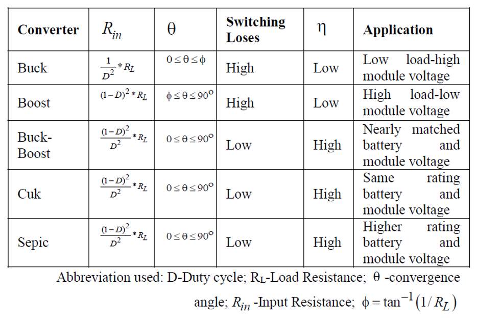
Table 1: different type of MPPT converter[10]
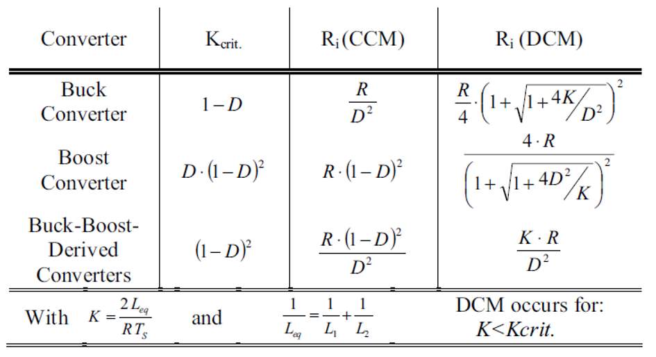
When it comes to the CCM and DCM, the CUK converter can be operated in two different modes based on the inductance and the voltage and the current of capacitor. The table shows the CCM and DCM modes is relevant to the input resistance (Ri, is the emulated resistance on the terminals of the PV panel), the equivalent inductance (
Leq), and the load connected to the converter (R). with the assumption of converters without losses. K is parameter that determine the CUK converter operating in different mode. If the magnitude of K is large enough, the converter will operate in the CCM. In the contrast, the DCM is owing to small K values. The boundary value of K between two modes is a function of duty cycle. Nevertheless, the converter would operate in CCM for all duty cycles with the condition of the magnitude of k being above one. Occasionally the mode boundary is always given based on the load resistance R. the determinant is the duty cycle D ranging from 0 to 1.
In terms of the CUK converter, it has the similar equation of buck-boost expression.
RiCCM∈0,∞ and RiDCM∈[2LeqTs,∞)
(25)
The CUK converter is able to sweep the whole I-V curve of a module in CCM. In the other words, it can sweep between
Vocand
Isc. [7]
Ri,and
Kcrit.for different DC-DC converter
The controller strategy of converter
There are several methods to control the photovoltaic system such as perturbation and observation method, fuzzy logic method and etc. In terms of P&O, the power of the PV system is versus the time. The algorithm of P&O MPPT is shown in fig11. if the magnitude of derivative of power with respect to voltage is positive, the output array of PV will be the same direction. Provided that the magnitude of derivative of power with respect to voltage is negative, the array of output voltage will be opposite with the first direction. This process would stabilize around the MPP points, which means
dpdv=0is constant.
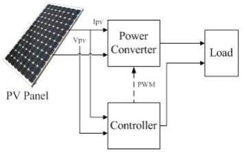
Figure 11: P V System Model [11]
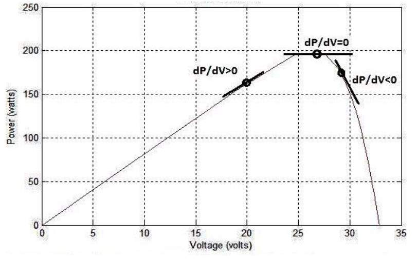
Figure 12: P-V Characteristics with P&O Algorithm basics[12]
When it come to the fuzzy logic controller, the structure of FL has two inputs and one output. Two inputs are error (E) and change in error (DEL-E), the input to the FL controller can be computered as
EK=PK-P(k-1)Vk-V(k-1)
(26)
and the change is shown below:
ΔEK=EK-E(k-1)
(27)
The duty cycle is computered to drive the switch of CUk converter
DK=DK-1+ΔD(K)
(28)
The option of switch
The choice of switch is an important part of the building of the circuit.the switch voltage stress comparison has shown in the tab. It is important to consider the input ripple when we choose the switch. The switch s usually connected with the source in series. For CUK converter, the input source has litter influence to the switch because they have lower current ripple and and noise.
The comparison of power semiconductor devices is shown in the tab3 the MOSFET switches on and off fast because it is a majority -carrier device. Moreover, no charge has to be removed ot injected to turn off or turn on the device. At hign blocking voltage the on state loss is high because of the high internal build-in resistance. Tab4 and tab 3 has show the selected parameters of switch depending on given basic requirement[13].
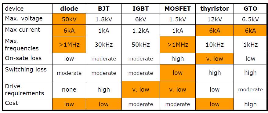
Table 3: Comparison of different switch device
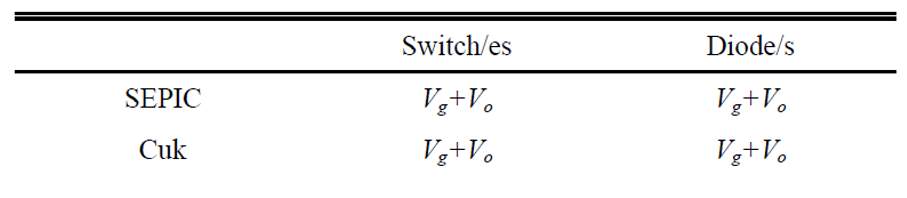
Table 4: voltage stress on semiconductor for the analyzed topologies
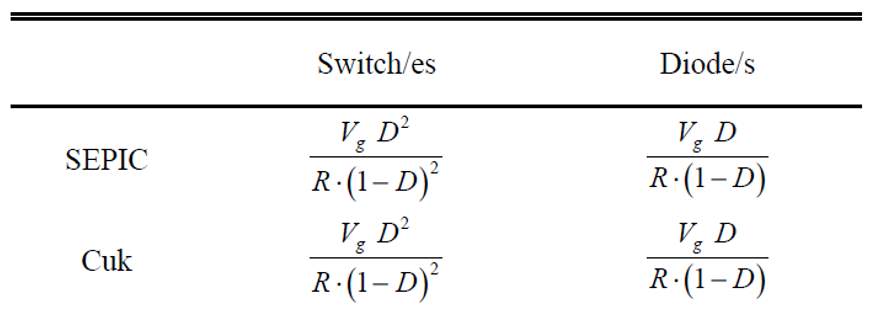
Table 5: average current across the semiconductor for the analyzed topologies
Conclusion
The CUK converter output voltage values can be higher or lower than input voltage. In addition, the harmonics of input and output current will be lower because of the inductors. These dominances are corresponding to PV application compared with different converters when it is operated in CCM mode. In CCM mode, the CUK converter can sweep whole I-V curve of the circuit. To get more smooth output current, it is necessary to have the close loop control strategy and the control strategy P&O for PV application.
References
[1] C. Werner, C. Breyer, A. Gerlach, and G. Masson, GROWTH REGIONS IN PHOTOVOLTAICS 2016 – UPDATE ON LATEST GLOBAL SOLAR MARKET DEVELOPMENT. 2017.
[2] R. D. Middlebrook and S. Cuk, “A general unified approach to modelling switching-converter power stages,” in 1976 IEEE Power Electronics Specialists Conference, 1976, pp. 18-34.
[3] R. A. Kordkheili, M. Yazdani-Asrami, and A. M. Sayidi, “Making DC-DC converters easy to understand for undergraduate students,” in 2010 IEEE Conference on Open Systems (ICOS 2010), 2010, pp. 28-33.
[4] A. Safari and S. Mekhilef, “Simulation and Hardware Implementation of Incremental Conductance MPPT With Direct Control Method Using Cuk Converter,” IEEE Transactions on Industrial Electronics, vol. 58, no. 4, pp. 1154-1161, 2011.
[5] K. Kumar, N. R. Babu, and K. R. Prabhu, “Analysis of integrated Boost-Cuk high voltage gain DC-DC converter with RBFN MPPT for solar PV application,” in 2017 Innovations in Power and Advanced Computing Technologies (i-PACT), 2017, pp. 1-6.
[6] S. P. Singh, A. K. Gautam, S. P. Tripathi, and B. Kumar, “Performance comparison of MPPT techniques using Cuk converter for photovoltaic energy conversion system,” in 2017 3rd International Conference on Computational Intelligence & Communication Technology (CICT), 2017, pp. 1-6.
[7] E. Duran, J. Galan, M. Sidrach-de-Cardona, M. B. Ferrera, and J. M. Andujar, “A new application of Duty Cycle Sweep based on microcontroller to obtain the I-V characteristic curve of photovoltaic modules,” in 2008 IEEE International Conference on Industrial Technology, 2008, pp. 1-6.
[8] R. Sankarganesh and S. Thangavel, “Maximum power point tracking in PV system using intelligence based P&O technique and hybrid cuk converter,” in 2012 International Conference on Emerging Trends in Science, Engineering and Technology (INCOSET), 2012, pp. 429-436.
[9] C. Jing and Y. J. Bao, “Characteristics analysis and comparison of buck boost circuit and Cuk circuit,” in 2013 5th International Conference on Power Electronics Systems and Applications(PESA), 2013, pp. 1-3.
[10] R. J. Mukti and A. Islam, “Designing an efficient photovoltaic system with maximum power point tracking technique by comparing different converter topologies,” in 2014 17th International Conference on Computer and Information Technology (ICCIT), 2014, pp. 235-240.
[11] S. Baraskar, S. K. Jain, and P. K. Padhy, “Fuzzy logic assisted P&O based improved MPPT for photovoltaic systems,” in 2016 International Conference on Emerging Trends in Electrical Electronics & Sustainable Energy Systems (ICETEESES), 2016, pp. 250-255.
[12] M. Farhat, O. Barambones, and L. Sbita, “A real-time implementation of MPPT-based on P&O method,” in 2016 5th International Conference on Electronic Devices, Systems and Applications (ICEDSA), 2016, pp. 1-5.
[13] H. Niu and R. D. Lorenz, “Evaluating Different Implementations of Online Junction Temperature Sensing for Switching Power Semiconductors,” IEEE Transactions on Industry Applications, vol. 53, no. 1, pp. 391-401, 2017.
Cite This Work
To export a reference to this article please select a referencing stye below:
Related Services
View all


Related Content
All TagsContent relating to: "Electronics"
Electronics regards the science and technology involved in the development of electrical circuits and electronic devices and equipment that use them.
Related Articles

DMCA / Removal Request
If you are the original writer of this literature review and no longer wish to have your work published on the UKDiss.com website then please: