Lateral Stability of Braced and Unbraced Steel Buildings - Methodology
Info: 2689 words (11 pages) Dissertation Methodology
Published: 26th Aug 2021
Tagged: Civil Engineering
Other sections of this dissertation example:
- Introduction
- Literature Review
- Methodology
3.0 METHODOLOGY
3.1 INTRODUCTION
This project compare braced and unbraced frames applied to euro code EC3 and British standard BS5950.
Method used to compare are hand calculation, and software such as strand7 and robot analysis. As an engineer we know that one only trial wouldn’t be satisfactory to make a point, so it has been created 6 floors building for each procedure and each procedure contain designing of EC3 and BS 5950 with two different dimensions as dimensions can affect the buckling and bending of the member, and P-delta factor has been analysed.
Drawing are been made on Revit (figure3.1) then transferred to robot for the analysis.
After each member design, a type of cross sectional area is been chosen from the Blue book based on their resistance formulated on the calculation.
3.2 LOAD TYPE
3.2.1 Dead Load
Dead load as well as known as the permanent load. All the members taking part on the structure and keeping together the structure are called dead Loads, as each has its own weight and effects the stiffens of the next permanent member. Good examples are: slab, beam column, roof, cladding etc… (PR SALTER BSc, 2004)
In order to have a secure and durable member a safety factor is used. As of the Euro-code imply a factor of 1.35, and BS standard imply 1.4. (PR SALTER BSc, 2004)
3.2.2 Live load
Live load known as a variable Load. This load changes from second to seconds depending on how many and what type of activities are induced. Anything that can be moved out or into the structure during its life time. Good example are: wind load, a person walking by or a small machinery installed for couple hours or days.
Due to the impossible prediction that can’t be made on the future loads a safety factor is used:
Euro-code imply a factor equal to 1.5 and BS Standard Imply 1.6. (PR SALTER BSc, 2004)
3.2 DESIGN FOR THE ULTIMATE LIMIT STATE
3.2.1 Load combinations BS 5950
The combination loads considered in this project are as follow:
1.4 × Dead load + 1.6 × Imposed load + 1.0 × Notional horizontal forces Combination 1
1.2 × Dead load + 1.2 × Imposed load + 1.2 × Wind load Combination 2
1.4 × Dead load + 1.4 × Wind load Combination 3
The notional horizontal forces should be taken as 0.5% of the factored dead plus imposed loads (BS 5950-1:1990 Clauses 5.6.3, 5.1.2.3).
(King, 20/12/2016), (PR SALTER BSc, 2004)
3.2.2 Lad Combinations Euro code
1.35 x GK+1.5 x QK
COMBINATION 1
1.35 x GK+1.5 x QK1+1.5 x 0.5 x QK2
COMBINATION 2
1.35 x GK+1.5 x QK1+1.5 x 0.7 x QK2
COMBINATION 3
COMBINATION 1
1.35 GK=considered the dead Load
1.5 QK=considered the as the Imposed load
COMBINATION 2
1.35 GK=considered the dead Load
1.5 x QK1=considered the as the Imposed load main variable
1.5 x 0.5 x QK2=Considered as the wind load with the combination factor of 0.5
COMBINATION 3
1.35 GK=considered the dead Load
1.5 x QK1=considered the as the Wind load main variable
1.5 x 0.5 x QK2=Considered as the Imposed Load wiith the combination factor of 0.7
3.3 DESIGN
This dissertation show how to design Bracing system for non-sway frames and sway frames, but as an engineer is well know that column and beam are members of a frame so to start designing first it has been determined type of beam used and column, therefore the following topics show what approach taken to design: column, beam and mainly bracing system.
3.3.1 Design of beams
A beam is a member that takes role as part of the frame, its bending and deflection could cause effect on the frame system, hence it has to be classified and designed as follow:
The floor system chosen in this dissertation is a situ concrete floor of 225 mm depth, with an impose load of 5
KNm2
, one way spanning.
Load combination has been calculated based on EURO-CODE (3.2.2) and British standard (3.2.1)
Shear force has been determined:
VED=wL2
W= distributed load due to the dead load and imposed load acting on the beam.
L= length of the beam
Then maximum moment which appears to be in the middle:
Mmax=wL28
Next step is to identify weather the beam is restraint or unrestraint, therefore an adequate section is chosen from the blue book table section. (southbank, 2016)
3.3.2 Design of columns
Colum is a member part of the frame as well. Buckling takes, place so it could affect the frame assisting on horizontal deflection or a sway due to the vertical and horizontal loads. Hence the stiffer and adequate section the less buckling appear.
A Column is subjected to compression due to that a buckling resistance is needed as follow:
- Verified buckling
NEDNbRd
Where;
NED=compration force acting on the column
NbRd=Design Buckling resistance
- Design buckling resistance should be taken as:
NbRd=X A fyΥM1
For class 1, 2, 3
NbRd=X Aeff fyΥM1
For class 4
- χ =
1ф+ф2-⅄2
- ф=0.5[1+α⅄-0.2+⅄2]
- ⅄=Afy NCr For class 1, 2, 3
⅄=Aefffy NCr
For class 4
Where; χ= Reduction factor
⅄=non dimensional slenderness
α=Imperfection factor
NCr=is the elastic critical force for the relevant buckling mode
Even though the cross section chosen are adequate, a slight of deformation will appear and this will lead as to verify and determine the Serviceability limit state.
3.4 DESIGN FOR SERVICEABILITY LIMIT STATE
3.4.1 Sway prediction
Once a frame designed for the ultimate limit state should, the next step should be analysing the frame as an elastic rigidly-jointed to determine the sway displacements.
The magnitude of sway displacements is caused by a number of factors: relative member stiffnesses, connection characteristics, the ratio of horizontal to vertical loading, and column behaviour. All these factors have a significant impact on the sway response of an unbraced frame.
Generally a common sway limit is h/300. For frames with a wider span bays, the sway displacement is likely to be below the above limit even under high wind loads. (MIStrucE, 2016), (J S HENSMAN BEng, 2016)
3.4.2 Sway limit
It is important to check that the sway on each storey is less than h/2000 cladding neglected (where h is the storey height) (MIStrucE, 2016) (Fattorini, 1995).The bottom storey sway is likely to be the most critical.
3.4.3 Redesign for stiffness
If sway deflections are higher than the limit, the frame may be modified to increase its stiffness, by increasing member size, such as: the beam depth, the column flange thickness or the connection stiffness (although they may not necessarily increase its moment resistance), or redesign as a braced frame.
3.4.4 First-order Elastic Analysis (Portal Method)
This method is used for the unbraced frame.
Every member designed is assumed to be under elastic phase in accordance to all design loads for limit states. (PR SALTER BSc, 2004)
Below method allow us to calculate the approximate axial shear and moment in each member.
Calculation has been carried twice:
Wind load on X direction (4 bays)
Wind load on Y direction (3 bays)
Please see below figure 3.4.4
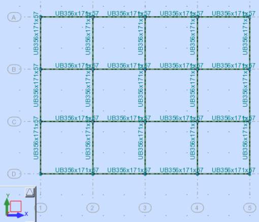
Figure 3.4.4 Plan view
Portal method allow as to solve indeterminate structure. In order to simplify the calculation, the structure is changed into determinate in order to use equilibrium equations by adding Pinned hinges were axial moment is assumed to be Zero positioned at the centre of each member. (Vary, 2016)
Below figures 3.4.41 show the fraction of shear force applied on members and the pinned hinges known as points of contra-flexure.
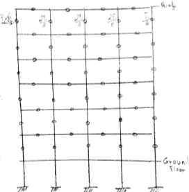
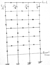
Figure 3.4.41 side view with pinned joints
On figure 3.4.41 the load applied in the interior columns are double that the loads on the exterior columns. Usually interior columns are stiffer because the carry more gravity load.
The Lateral loads are determined as follow:
w=wind load x width bay=kNm UDL all along the hieght of the building
F=w x h2=KN ( total shear acting on points of contraflaxuere)
Where h= Height of one floor
w= UDL (Vary, 2016)
The above shear calculation will be repeated for each floor taking in consideration the deference in height.
The next step is to determine the moment on each member as follow for:
Wind load on X direction (4 bays)
M= F8xh2=KNm ( moment due to the shear on the external column)
M= 2F8xh2=KNm ( moment due to the shear on the internal column)
Wind load on Y direction (3 bays)
M= F6xh2=KNm ( moment due to the shear on the external column)
M= 2F6xh2=KNm ( moment due to the shear on the internal column)
Moment on the beams:
M= M1+M2 =KNm ( moment on the beam)
Where:
M1=moment induced from the upper floor
M2=moment induced from the lower floor
(Vary, 2016)
3.5 BRACING
3.5.1 General
Using a triangulated system, all the members of a bracing system need to be verified and designed based on the design forces due to different combinations of actions. It is recommended to make all diagonal members the same size, adequate to resist the largest design force.
- Verification must be carried out by checking the resistance of the attachment column to beam, resistance of 1% of the vertical force on the column.
- Check all the horizontal forces in the column if been transferred into the vertical bracing system.
3.5.2 Bracing design
Once the wind load is determined, calculation as follow:
W=wind load x height of building (total wind load)
w=W2height of building distributed wind load
F=w x storey hieght ( load acting on each node)
(Vary, 2016)
Once determined the forces, each node has to be resolved relatively to the forces applied, therefore a design size is chosen from the blue book depending on the force acting on each bracing.
For consistency two size are taken into consideration.
3.6 Frame Deflection
Deflection for each frame has been calculated, because on these dissertation the aim is to compare the behaviour into sway of braced and unbraced frame.
Deflection can be determined by 2 methods:
-slope deflection method
-unit load method.
In this dissertation the deflection of frame has been carried out by using Unit load method which practically quicker way to do it by using the volume integration table, please see Appendix xxx.
3.6.1 Unit load Method
One of the easiest and more precise way to analyse deflection is the principle of virtual work, great analytical tool to analyse determinate and indeterminate structures. This principle states that the sum of the external work done is equal to the sum of the internal word done.
The Unit load method apply the principle of virtual work to determine the displacement of the structure as follow (Datoo, 2015):
- The deformation of the structure has been determined using the externally applied loads.
- Virtual unit load applied at the point and into the direction where displacement is assumed to appear.
- Determine the internal work due to the internally force and unit load.
- Use the principle of virtual work by equating the sum of the external equal to the sum of the internal relative to the specific point chosen.
1x∆ = ∑∫0LM0 M1EIds
EXTERNAL WORK=INTERNAL WORK
Where:
∆=diflection
M0=Moment due to internal work M1=moment due to unit load
3.6.12 Volume integration
Volume integration table is used by comparing the bending diagram due to internal work of each member with its correspondent bending diagram formulate from the unit load applied. If the bending moments due to the internal work and the unit load are on the same side then the product is positive but if they are on the opposite side then the product of the two is negative (Datoo, 2015). Please find Volume integral Table on Appendix xxx.
3.7 Frame Stability
Any frame structure should be examined for susceptibility to sway instability into second order effect. (Eng, 2009)
3.7.1 Second order
P∆ effect
If
acr
> 10 any second order effect are good enough to be neglected. This check is an UlS check (PR SALTER BSc, 2004), (Eng, 2009), the combination considered is the equation with wind as a leading action as follow:
Euro code: COMBINATION 3 on section 3.2.2
UK standard: COMBINATION 3 on section 3.2.1
Calculation has been processed as follow:
- Design value of wind load as leading action
- Design value of vertical Loads in combination with wind Load as leading action.
The bracing carry also horizontal loads induced by the imperfections. This loads are equivalent to 1/200 (0.5%) of the total permanent and variable factored loads acting on each floors and roof. Each bracing bay will be distributed a value equivalent of ½ of the total horizontal load. (Eng, 2009), (D G BROWN BEng, 2009)
- Each load above on point 2 has been added to the loads on point 1.
- Sway analysis is carried in accordance to the deflection values obtained on section 3.6.
- Frame stability verified using the following formula:
acr=HEdVEd x h∆ >10 CITATION MEB091 l 2057 (Eng, 2009)
3.8 Frame analysis software method
Different software has been used to determine the behaviour of the frame.
3 buildings are designed on Revit:
- Unbraced frame
- K-Braced frame
- X-Braced frame.
Each drawing is transferred into robot for analysis applying euro-code factors and British standard factors.
On the other hand the frame systems above are analysed on strand 7.
Cite This Work
To export a reference to this article please select a referencing stye below:
Related Services
View all


Related Content
All TagsContent relating to: "Civil Engineering"
Civil Engineering is a branch of engineering that focuses on public works and facilities such as roads, bridges, dams, harbours etc. including their design, construction, and maintenance.
Related Articles

DMCA / Removal Request
If you are the original writer of this dissertation methodology and no longer wish to have your work published on the UKDiss.com website then please: