Literature Review of Lateral Stability of Braced and Unbraced Steel Buildings
Info: 3166 words (13 pages) Example Literature Review
Published: 26th Aug 2021
Tagged: Civil Engineering
Other sections of this dissertation example:
- Introduction
- Literature Review
- Methodology
2.0 LITRATURE REVIEW
2.1 Introduction
The following chapter provides an overview of the different type of braced frames and non-braced frame respectively to their stiffness performance advantages and modelling considerations. The historical background is outlined shortly in this review and the correspondent difference on the practice code based on EC3 and BS5059.
2.2 Practice code EURO-CODE
2.2.1 Background of Euro code 3 (EC3)
European Code, or better known as Euro code, was initiated by the Commission of European Communities as a standard structural design guide. It was intended to smooth the trading activities among the European countries. Euro code is separated by the use of different construction materials. Euro code 1 covers loading situations; Euro code covers concrete construction; Euro code 3 covers steel construction; while Euro code 4 covers for composite construction. (HAN, NOVEMBER, 2006)
2.2.2 Scope of Euro code 3: Part 1.1 (EC3)
EC3, “Design of Steel Structures: Part 1.1 General rules and rules for buildings” covers the general rules for designing all types of structural steel. It also covers specific rules for building structures. EC3 stresses the need for durability, serviceability and resistance of a structure. It also covers other construction aspects only if they are necessary for design. Principles and application rules are also clearly stated. Principles should be typed in Roman wordings. Application rules must be written in italic style. The use of local application rules are allowed only if they have similar principles as EC3 and their resistance, durability and serviceability design does not differ too much. EC3 stresses the need for durability, serviceability and resistance of structure (Taylor, 2001). It also covers other construction aspects only if they are necessary for design. (HAN, NOVEMBER, 2006)
2.2.3 Design Concept of EC3
All designs are based on limit state design. EC3 covers two limit states, which are ultimate limit state and serviceability limit state. Partial safety factor is applied to loadings and design for durability. Safety factor values are recommended in EC3. Every European country using EC3 has different loading and material standard to accommodate safety limit that is set by respective countries. (HAN, NOVEMBER, 2006)
2.2.4 Application Rules of EC3
A structure should be designed and constructed in such a way that: with acceptable probability, it will remain fit for the use for which it is required, having due regard to its intended life and its cost; and with appropriate degrees of reliability, it will sustain all actions and other influences likely to occur during execution and use and have adequate durability in relation to maintenance costs. It should also be designed in such a way that it will not be damaged by events like explosions, impact or consequences of human errors, to an extent disproportionate to the original cause. (HAN, NOVEMBER, 2006)
Potential damage should be limited or avoided by appropriate choice of one or more of the following criteria: Avoiding, eliminating or reducing the hazards which the structure is to sustain; selecting a structural form which has low sensitivity to the hazards considered; selecting a structural form and design that can survive adequately the accidental removal of an individual element; and tying the structure together. (HAN, NOVEMBER, 2006)
2.2.5 Ultimate Limit State
Ultimate limit states are those associated with collapse, or with other forms of structural failure which may endanger the safety of people. Partial or whole of structure will suffer from failure. This failure may be caused by excessive deformation, rupture, or loss of stability of the structure or any part of it, including supports and foundations, and loss of equilibrium of the structure or any part of it, considered as a rigid body. (HAN, NOVEMBER, 2006)
2.2.6 Serviceability Limit State
Serviceability limit states correspond to states beyond which specified service criteria are no longer met. It may require certain consideration, including: deformations or deflections which adversely affect the appearance or effective use of the structure (including the proper functioning of machines or services) or cause damage to finishes or non-structural elements; and vibration, which causes discomfort to people, damage to the building or its contents, or which limits its functional effectiveness. (HAN, NOVEMBER, 2006)
2.2.7 Actions of EC3
An action (F) is a force (load) applied to the structure in direct action, or an imposed deformation in indirect action; for example, temperature effects or settlement. Actions are classified by variation in time and by their spatial variation.
In time variation classification, actions can be grouped into permanent actions (G), e.g. self-weight of structures, fittings, ancillaries and fixed equipment; variable actions (Q), e.g. imposed loads, wind loads or snow loads; and accidental loads (A), e.g. explosions or impact from vehicles. Meanwhile, in spatial variation classification, actions are defined as fixed actions, e.g. self-weight; and free actions, which result in different arrangements of actions, e.g. movable imposed loads, wind loads, snow loads. (HAN, NOVEMBER, 2006)
2.3 Practice code BS 5950
2.3.1 Background of BS 5950
BS 5950 was prepared to supersede BS 5950: Part 1: 1990, which was withdrawn. Several clauses were technically updated for topics such as sway stability, avoidance of disproportionate collapse, local buckling, lateral-torsional buckling, shear resistance, members subject to combined axial force and bending moment, etc. Changes were due to structural safety, but offsetting potential reductions in economy was also one of the reasons.
BS 5950 comprises of nine parts. Part 1 covers the code of practice for design of rolled and welded sections; Part 2 and 7 deal with specification for materials, fabrication and erected for rolled, welded sections and cold formed sections, sheeting respectively; Part 3 and Part 4 focus mainly on composite design and construction; Part 5 concerns design of cold formed thin gauge sections; Part 6 covers design for light gauge profiled steel sheeting; Part 8 comprises of code of practice for fire resistance design; and Part 9 covers the code of practice for stressed skin design (HAN, NOVEMBER, 2006).
2.3.2 Scope of BS 5950
Part 1 of BS 5950 provides recommendations for the design of structural steelwork using hot rolled steel sections, flats, plates, hot finished structural hollow sections and cold formed structural hollow sections. They are being used in buildings and allied structures not specifically covered by other standards. (HAN, NOVEMBER, 2006)
2.3.3 Design Concept of BS 5950
There are several methods of design, namely simple design, continuous design, semi-continuous design, and experimental verification. The fundamental of the methods are different joints for different methods. Meanwhile, in the design for limiting states, BS 5950 covers two types of states – ultimate limit states and serviceability limit states. (HAN, NOVEMBER, 2006)
2.3.4 Ultimate Limit States
Several elements are considered in ultimate limit states. They are: strength, inclusive of general yielding, rupture, buckling and mechanism formation; stability against overturning and sway sensitivity; fracture due to fatigue; and brittle fracture. Generally, in checking, the specified loads should be multiplied by the relevant partial factors γf given in Table 2. The load carrying capacity of each member should be such that the factored loads will not cause failure. (HAN, NOVEMBER, 2006)
2.3.5 Serviceability Limit States
There are several elements to be considered in serviceability limit states – Deflection, vibration, wind induced oscillation, and durability. Generally, serviceability loads should be taken as the unfactored specified values. In the case of combined imposed load and wind load, only 80% of the full specified values need to be considered when checking for serviceability. In the case of combined horizontal crane loads and wind load, only the greater effect needs to be considered when checking for serviceability. (HAN, NOVEMBER, 2006)
2.3.6 Loading
BS 5950 had identified and classified several loads that act on the structure. There are dead, imposed and wind loading; overhead traveling cranes; earth and ground-water loading. All relevant loads should be separately considered and combined realistically as to compromise the most critical effects on the elements and the structure as a whole. Loading conditions during erection should be given particular attention. Where necessary, the settlement of supports should be taken into account as well. (HAN, NOVEMBER, 2006)
2.4 Wind-moment frame
On an Unbraced steel frame, a rotational stiffness of the beam-to-column connections is more of the concern. Under vertical load the connections are assumed to be pinned. This design is well known as the wind-moment method or wind-connection method and is used widely in the UK and North America. The wind-moment method is described as of low rise frames design. The procedures for the design are given in the publication of BS 5950. (J S HENSMAN BEng, 20/12/2016), (P R SALTER BSc, 1999)
2.4.1 Benefits of the wind-moment method
One of the main advantages of the wind-moment method is its simplicity. There is no relation between internal moments/forces with the relative stiffness of the frame members, because the frame is considered as statically determinate. From a construction viewpoint, the main advantage of wind-moment frames is the simplicity of the steelwork compared to a fully rigid construction. Steelwork contractors are more concerned with making the connections, and it is estimated that the fabrication and workshop handling costs related with the connections can be as high as 50% of the total cost of the erected steelwork. (J S HENSMAN BEng, 20/12/2016), (P R SALTER BSc, 1999)
2.4.2 Choice of wind-moment method
The designer can quickly determine whether the wind-moment method will be adequate for a given frame by using the flowchart provided in Figure 2.4.2. An alternative design method should be considered if the frame is dominated by SLS Sway deflection. (J S HENSMAN BEng, 2016)
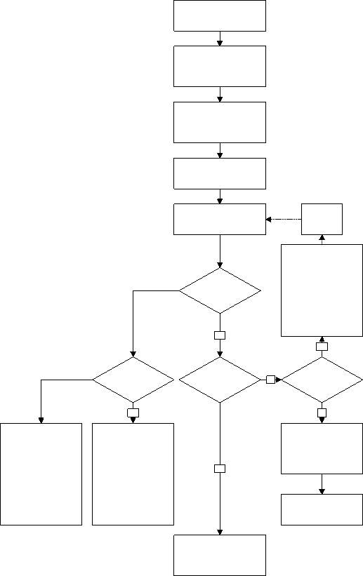
Figure 2.4.2 (J S HENSMAN BEng, 20/12/2016)
2.4.3 Principles of wind-moment method design
The assumption made at a design stage are the following:
– Under vertical loads the connections are assumed to be pinned (Figure 2.4.3(a)),
– Under lateral loads the connections are assumed to behave as rigid joints, with points of contra flexure appearing at the mid-height of the columns and at the mid-span of the beams (Figure 2.4.3(b)).
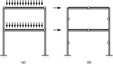
Figure 2.4.3 (J S HENSMAN BEng, 20/12/2016)
2.5 Necessary checks
The publication in BS 5950-1:2000 gives an explanation of the three below methods of checking in plane stability:
(a) The Sway-check method
(b) The Amplified Moment method
(c) Second-order analysis
2.5.1 The Sway-check method
The Sway-check method mainly is used for portals which comply the following geometrical limitations:
-Span/height to eaves is not more than 5.
-Rise of apex above column tops is not more than span/4 for symmetrical spans or a value given by a formula for a symmetric rafters.
-Either the notional sway deflection from notional forces (calculated by first order analysis) is not more than h/2000, or the span/depth ratio of the rafters is within a limit given by a formula. (MlStructE, 20/12/2016)
2.5.1.2 Advantages and disadvantages
The Sway-check method is the easiest method and provide cheaper designs if the frame is stiff enough to comply either the h/2000 check or the formula check based on the section sizes selected either to induce the required stiffness or to satisfy the Serviceability Limit State (SLS) requirements. This method will often provide the most economical designs. When using the Sway-check method, the steel strength (e.g. S275 or S355) has no effect on the in-plane stability calculation. (MlStructE, 20/12/2016)
2.5.2 The Amplified Moment method Range of application
If the design does not comply the limitation of the sway check method then The Amplified Moment method comes into roll. It may be used for portals that are not tied portals and which have an elastic critical buckling ratio,
2.5.3.1 Advantages and disadvantages
Second-order analysis is simple to apply in software. Flexible frames such as multi-span frames provide a lower cost designs. It can provide less cost effective designs than the other methods for stiffer frames because it will always calculate a reduction of frame strength due to the second-order (P-delta) effects. The Second-order method does allow the idea of higher strength steel (grade S355 steel). (MlStructE, 20/12/2016)
2.6 Bracing system
Two type of bracing frame are identified in multi-storey design: Horizontal bracing and vertical bracing.
-Vertical bracing resists the lateral loads and produce great stability against sway to the structure. Vertical bracing transfer the loads carried out to the ground and some part of it to the roof which these act as horizontal diaphragms.
– Horizontal bracing, generally transfer the horizontal forces implemented by floor plate action, caused due to wind pressure on the cladding to the planes of vertical bracing.
2.6.1 Horizontal bracing
A horizontal bracing system is necessary at each floor, in order to transfer lateral loads (mainly the forces transferred from the perimeter columns) to the vertical bracing that deliver lateral resistance. There are two horizontal bracing systems that can be installed in multi-storey braced frames: Diaphragms Discrete triangulated bracing.
Typically, horizontal bracing systems span between columns, which are connected to the vertical bracing. This type of Brace arrangement often known as truss, with a depth ratio equal span/20 or equal to the bay centres (D G BROWN BEng, 2009)
In terms of design, simply the truss is considered as a simple supported and the reaction at the end of the truss can be calculated, consecutively used to design the critical bracing member,. most of the time is suggested to use same member size throughout the bracing system.
2.6.2 Vertical bracing
In order to avoid any torsional effects (twist on plan) due to the wind or lateral forces it is preferable to introduce vertical bracing at or near the perimeter of the structure. Mainly bracing is installed around service cores, lift shafts, stair. Some of the time bracing arrangements may have to be modified due to the architectural arrangements to facilitate the instalment and location bracing members. In some cases intermediate columns may have to be installed to act as part of the bracing system. (D G BROWN BEng, 2009)
In a multi-storey building most common vertical bracings are installed diagonally between two columns (inclined at approximately 45° are suggested). In which case they are considered the most efficient system compared to other arrangements. In the inclined bracing the connection between the bracing itself and beam/column (junction) are compact. Wide bracing systems will result in more stable structures.
The minimum brace is a single diagonal, as shown, where has to be designed either for tension or compression. . (D G BROWN BEng, 2009) (Fattorini, 1995)
The design conducted for vertical bracing frame must be able to resist to the following:
– Wind loads
– Equivalent horizontal forces, representing the effect of initial imperfections
– Second order effects due to sway (if the frame is flexible). Definition of second order effects in Section 2.5.3.
2.7 Internal moments and forces
Internal forces and moments are determined using statics. In a statically indeterminate structure are determined using either:
- Elastic global analysis
- Plastic global analysis
Internal forces can be generally be determined using: first order theory based on the structure initial geometry, or can be used second order theory due to the deformation of the structure.
As continuing first order may be used in the following cases:
- Braced frames
- Non-sway frames
And the second order may be used in all cases. (PR SALTER BSc, 2004)
2.7.1 Elastic global analysis
1. The relation between STRESS-STRAIN is assumed to be linear
2. The calculated bending moment is modified by redistributing up to 15% of the peak calculated in any member based on:
a) The applied load is in equilibrium with the internal forces and moments in the frame,
b) All the members have a CLASS1 or CLASS2 cross-section. (PR SALTER BSc, 2004)
2.7.2 Plastic global analysis
Plastic global analysis can be induced using RIGID-PLASTIC method, and lateral restraint shall be provided at all plastic hinge location where hinge rotation can occur under any load case. This method does not apply the second order theory. (PR SALTER BSc, 2004)
Cite This Work
To export a reference to this article please select a referencing stye below:
Related Services
View all


Related Content
All TagsContent relating to: "Civil Engineering"
Civil Engineering is a branch of engineering that focuses on public works and facilities such as roads, bridges, dams, harbours etc. including their design, construction, and maintenance.
Related Articles

DMCA / Removal Request
If you are the original writer of this literature review and no longer wish to have your work published on the UKDiss.com website then please: