Wearable Chipless RFID Tag for Biomedical Applications
Info: 7508 words (30 pages) Dissertation
Published: 9th Dec 2019
Tagged: Medical Technology
Abstract—- The design, simulation and measurement of the planar circular shaped microstrip antenna on a good substrate with dielectric permitivity, ϵ_r=2.45 at 2.43 and 5.8 GHz have been analysed. It found that circular patch antenna could be preferred for wearable systems in various environmental conditions. The most important aspect is to choose proper dielectric material and structure of the design antenna. These two aspects are also important for designing antennas in breathing monitoring system. The systematic design procedure of the circular shaped microstrip antenna alongwith prototype development has been reviewed in this article. The different antenna parameters of the design results such as reflection coefficient, gain, radiation patterns have been discussed. The verification of antenna performance for various environmental conditions is a new direction of this article. It is clear that the proposed antennas easily overcome the propagation test in different wearable conditions and takeout the fear factor for the designer to incorporate the microstrip antenna in breathing monitoring as well as other related applications.
1 Introduction:
At present, radiofrequency identification (RFID) techniques play a vital role in detecting a monitoring things by means of low power and cost effective technology. The sensors and signal processing units can be integrated with RFID devices to achieve better performances. It is capable of monitoring real time biomedical parameters such as temperature, blood pressure, heartbeat, glucose content, human behaviour etc and location of patients in the medical or residential environment. Presently, RFID is predominant due to its broad applications but most of the time these systems are not visible to the users. The RFID system basically, comprises of a Reader (or interrogator) and a tag (or transponder). The Reader or interrogator is the main unit, which provides the electromagnetic energy to the tag. It transmits and receives the radio signals to and from the tag. The reader is controlled either by a computing system or by the execution of computer programs. In market places or general stores, fixed readers are connected to telephone cables, while hand held readers are used in mobile devices. The Tag is the device that can be fixed on the product or element to be tracked. Most RFID tags are without any internal battery and are called passive tags [1]. The tag gets energy from the RF field of the reader. The tag creates its own voltage by rectifying the induced voltage from the Reader’s RF energy. The tags with internal battery or energy source behave similar like passive tags with improved performances are called active tags. These tags provide energy to the electronic circuit in it and generate responses with the help of internal battery. Their activation is mostly produced by the reader signal.
The RFID tag can be a good alternative of the barcode because of its multifarious advantages, like its non–line-of-sight reading and long distance tracking range capability [2], [3]. Present advancements in Chipless RFID technology dig out many exciting possibilities for RFID to address new opportunities like product tracking to human tracking. Other than the silicon chip (IC) used for identity extraction, chipless RFID uses an electromagnetic signature for data encoding with low cost of the RFID tags as low as barcodes [4], [5]. The retail manufacturing needs smart tagging system so that the individual item can be tracked. The most popular ‘barcode system’ cannot offer a smart communication technique due to human involvement in the process [1]. Basic RFID system is shown in Figure1.
The emergent requirements for cost effective, low power, conformal and long-lasting RFID sensors with sensing abilities is motivated with applications like: temperature and humidity tracking, transport and storage of medical products and bio-sensing. The important task in these applications is the need for cost effective ecofriendly wireless sensors that can easily be implemented in different environment conditions.
2. Why Chipless RFID?
The most important factor is the cost of the tags in deploying an RFID system for day-to-day usage. This is the main reason for which barcodes still hold way in everyday consumer products, although an RFID system has many benefits over barcodes. The actual cost of RFID tags arises from the IC chip embedded on the tag. The best solution to this problem can be RFID tags without any chips and called ‘chipless RFID tags’. The business market of the chipless tags is supposed to be the largest one in future [5].
This technology requires a smart reader, which can handle all the relevant commercial operation on attaining the specific identification of the tag. This technology is currently confined to a small read range and no literature is available for any anti-collision algorithm of this technology [2]. A classification of the present advancements in this technology is given in Figure 3[3]. However, the smart antennas with agile beams and nulls steering capabilities, adaptive directionality, and capability to enhance signal-to-interference ratio have significance for the effective reading of the tags. The abovementioned smartness of the reader for the chipless
tags may come from the smart antennas.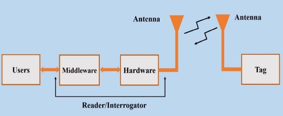
Normally, antennas are designed for tag as well as reader of a RFID system. The tag antennas can be categorised as time-domain reflectometry (TDR) or retransmission and backscattering or millimetre-wave chipless tags and printed coil nearfield tag antennas, shown in Figure1.
Fig.1 RFID System
The printed coil tag antenna can be constructed with a special type of chipless tag that utilises nearfield printed coil for high frequency chipless tag applications as discussed in [6-7]. The different chipless RFID tags are compared in Table 2.1 [6].
In case of TDR chipless tags, the antennas must possess omnidirectional radiation patterns and having ultra wideband properties. Hence, mostly dics loaded monopole antennas are the good examples of this category.
The back scattering chipless RFID tags are having high Q. Hence, they possess low bandwidth to encode data in the antenna structure. Planar antennas (e.g. microstrip, Dielectric Resonator antenna etc) are generally high Q features and are used in these types of tag designs.
The feeding technique for near field RFID system can either be capacitive or magnetic. The retransmission and back scattering tag antenna with their performances are shown in Fig. 2.The antenna performs as an proficient radiator (in case of retransmission) and a reflector (in case of back scattering tags) [7]
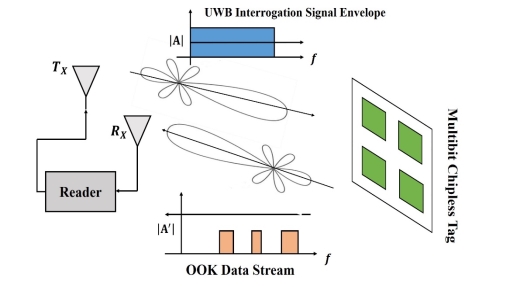
Fig.2 Principle of operation of Backscattering RFID Tag
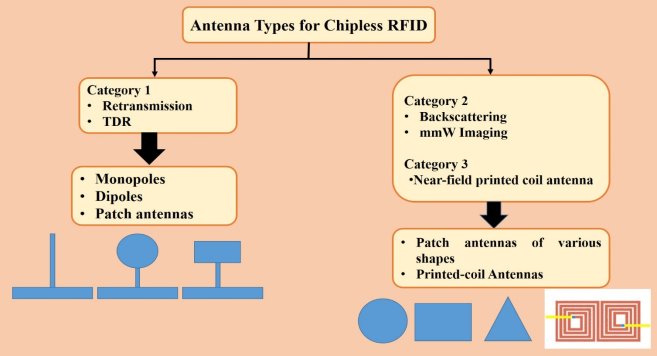
The first two category chipless RFID tags work on the principle of remote magnetic (including EM technology), transistor less, or transistor circuits (Figure 3&4). Chipless RFID tags using EM technology have variations such as microstrip/printed resonator circuits, chemical resonator circuits, SAW circuits, and arrays of printed radars [8-11]. However, Chipless tags working on the Barkhausen principle or the magnetostriction principle rely solely on the magnetic properties of the material of the tag. Some chipless RFID tags use thin-film transistors, which are organic or polymer in nature [12-14].
Figure 3. Category of chipless RFID tags and related antennas.
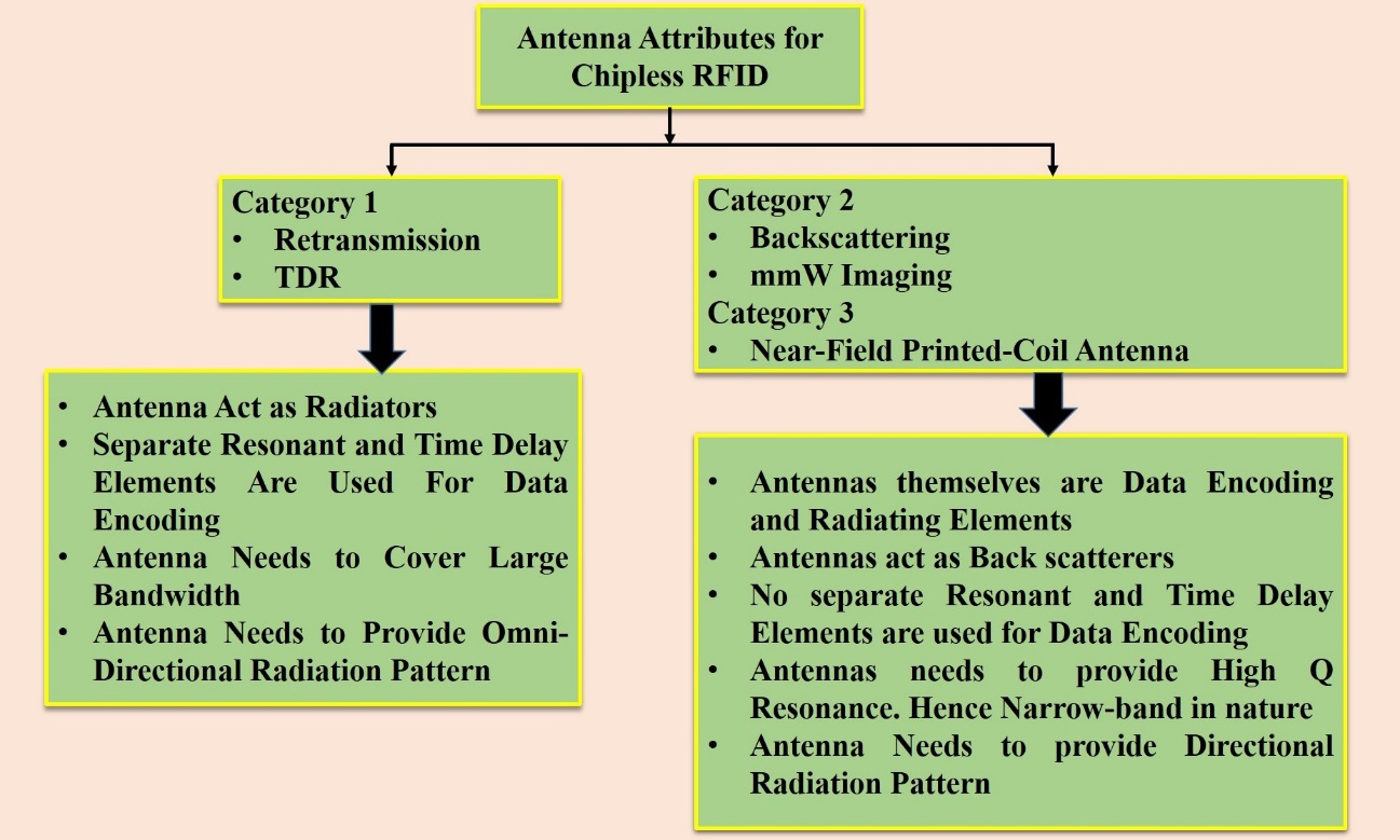
Fig4 The design aspects of the two RFID tag categories
3. Challenges in RFID tag design
In an RFID system, electromagnetic waves are used as the source of communication. Antennas are the spatial filters that couple guided electromagnetic energy to free space electromagnetic energy and vice versa to enable communication in an RFID system. Any conducting structure can be termed to be an antenna, but the efficiency with which the structure can transform the energy is the key determining factor on how easily communication can be established in the system.
Passive antennas are mostly used in RFID systems and are reciprocal in their behaviour. This means that the antenna behaves in a similar fashion irrespective of its transmission and reception modes. According to Faraday’s law, when an antenna is placed in a time-varying electromagnetic field, it induces electrical potential at its terminals and thus acts like a receiver. Like any component, when designing any antenna, certain characteristics such as antenna gain, bandwidth, radiation patterns, and polarization are the key parameters that have to be treated properly while designing it.
Challenges involve in the nonexistence of the IC chip in a chipless tag that removes the tag’s signal processing ability. Hence, no handshaking protocols can be employed in the chipless tag. Since the operating frequency limits the size of the tag antenna, the backscattering radiation power to the reader is reduced. An array antenna may eliminate this situation, and again, the tag size becomes bulky to house multiple elements. Hence, the design would be more difficult [4]–[6].Consequently, antenna design plays a vital role in chipless tag system with respect to the chip based tag system.
4. RFID Sensors for Biomedical applications
The increasing demand for low cost, low power, conformal RFID sensors with sensing abilities is motivated by applications like: temperature, humidity, and bio sensing. The main challenge in these applications is the need for cost effective wireless sensors that can be easily implemented in various environmental conditions.
Presently, wearable RFID sensor attracts major interest and becomes another rapid developing field in advance research. Compact, flexible, and reliable wearable RFID sensors are always in demand in order to maintain a quick and secured body area network.
The chipless RFID sensor does not need a silicon chip, and hence, the cost of RFID sensing technology reduces substantially. Additionally, the sensor is entirely printable and passive, and thus can survive extreme cases of weather conditions and environments. Despite relying on radio waves (RF), innovative designs of the chipless RFID tags can also be printed on water bottles and metals [15]. These exceptional features support chipless RFID in distinctive applications, which is not possible in case of both barcodes and chip based RFID tags. Few examples comprise low cost article tagging for ID cards, soft drink cans, banknotes, books, water bottles etc. Additionally, chipless RFID sensors [16-19] are capable of measuring/monitoring real time parameters such as temperature, heartbeat, humidity, pH and stress/strain/pressure, have opened up a new field of research. This research proposal offers major developments in fully printable very low cost chipless RFID tag sensing devices for monitoring soil moisture, temperature, soil stress and pH levels. Nemai Karmakar et al, [20] have developed a fully printable, low cost, multi-bit RFID tag that was demonstrated in 35-bits. This tag is now in commercial development in pilot studies on Australian banknotes. The concept involves printing a simple polymer substrate (Australian banknote substrate in the commercial application) with several miniature, multi-resonant circuits that backscatter broadband microwave radiation in the range 3-7 GHz. Each multi-resonant circuit backscatters different, but very particular frequency signals (Figure 5). In the most recent work, tags with receiving and transmitting antennas have been reliably printed on Australian polymer banknote substrate, addressed and read remotely (non-contact) over a distance of up to 25 cm. Many applications with security and data integrity required short distance communication.
Figure 5 shows a multimode (humidity-temperature) chipless RFID sensor and its frequency response. The passive RFID tag sensor uses polymer materials for environmental parameter sensing. It can perform several physical parameters sensing within the tag itself. Additionally, the chipless RFID sensor are better than conventional sensors due to economic, longer storage time, robustness and lower radiated power. Due to their potential benefits, chipless RFID sensors have the potentials to penetrate many fields including biomedical or health care.
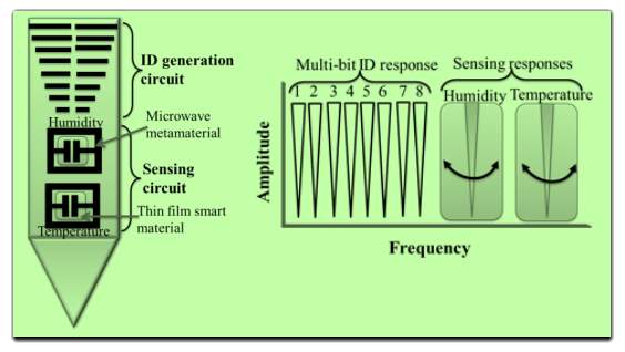
Fig 5. Multi Sensor Tag
5. Tag and Reader design consideration
Substantial investigations can be made in the areas of antenna design in 2.4GHz to 5.8 GHz wireless monitoring systems for the detection of heart diseases with the following scientific development [21]:
- Design of a conformal and small microstrip patch antenna, which can easily be implemented on Wearable device ;
- Design of a small size, narrow band pass filter with good selectivity;
- Design of a GaAs high power amplifier Monolithic microwave integrated circuit;
- Low cost system and ;
- Outstanding performance of the designed antenna.
5.1Reader Antenna Design
In general, Reader antennas are similar to tag antennas. However, this case gain has to be larger, and size is no big issue. A larger reader antenna is not necessarily a longer read range. In fact, the optimal antenna radius for a given read range is
For the chip based tag, maximum read range [26] is given in equation (2)
PLF= polarization loss factor between tag and reader, Greader = the gain of reader antenna, Gtag_normalized = normalized gain of the tag antenna, and Pi,min = the minimum sensitivity of the tag [27].
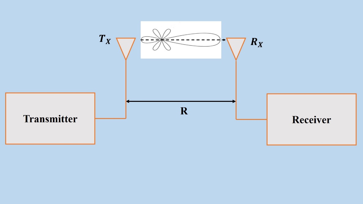
Fig.6 RCS measurement of a Tag
1. Two way transmission; field power reduced by 1/R4
2. Radar range equation:
R1 = separation between and the transmitting antenna, R2 = distance between target and the receiving antenna. In case of chipless reader, the same antenna can be used in the monostatic condition where as two antennas with the equal gain can be placed side by side in the bi-static condition [28]. Therefore, radar range equation reduces to
The RCS in (7) signifies the power reradiated from the target. The reflection coefficient shows the percentage of power reradiated by the target. Directivity is the ratio of the power back scattered in the radar’s direction to the power that would have been backscattered by the isotropic source. The RCS [8] is approximated for a small flat plate in (8). The detail measurement diagram is shown in Figure 7(b).
σplate=4πW2h2λ2
(8)
where ‘W’ and ‘h’ are the width and height of the flat plate respectively and λ is the wavelength of the frequency of operation.
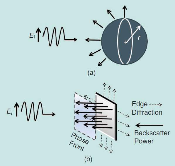
Figure 7. RCS calculation of the chipless tag (a) sphere and (b) a flat plate
7. Design of Chipless tag and Reader for wearable Devices
Generally, chipless tags are categorised into three category. The time domain reflectometry (TDR) chipless tags are under category 1. These are also called retransmission tags. The backscattering or millimetre-wave image based tags are classified under category 2. Similarly, category 3 chipless RFID tags are classified as special type. It uses printed coil antennas for implementation of coil resonators in near filed at high frequency [31]. In case of category 1, the antennas and data coding elements are designed as separately. In category 2, the antenna itself is a resonant data coding element and reflector. Hence, these features should be treated separately. Figure 4 describes features of two important chipless tags viz. TDR and backscattering tags besides their design necessities.
Wearable systems have received a widespread attention due to prospective future of sensing technology and body centric wireless systems [36]. In general, there is an increasing market for low cost textile antennas, which will undergo bending and stretching of materials. Wearable tags offer tracing and identifying goods over numerous media. Improved manufacturing creates the demand for wearable devices due to its ability to embed with fabrics of stretchable and soft materials. Present trend is to develop the fabrication of antennas with perfect electric conductor (PEC), which has some restrictions like antenna elements get oxidised and corroded. Besides, printing of tags using conductive inks of copper or silver usually needs very high sintering temperature. It restricts the choice of fabric substrates.
Carbon based nanomaterial, as graphene could be a better solution for designing RFID tags. Inks made from graphene provide better features and cost effective materials. Since graphene properties vary with physical stress and humidity, the change in electrical parameters like power of the tag or read range occur by using graphene based antenna [38-40]. Hence, it can be used in wearable sensor systems.
The fabrication techniques of graphene based Ultra High Frequency tags place on fabric substrate are discussed in [41]. The ink consisting of graphene nano-platelets is placed on a substrate of cotton material to prepare the tags. The tag properties are measured with stretching, bending, and high humidity environment. For this tag, read range is achieved around 1.6 m, and extends to 3.2 m in perfect humidity environment. Experimental verification shows that stretching offers harmful effect on these tags. Hence, stretching substrates cannot be used for these tags. Moreover the experimental performance proves that graphene based tag has outstanding response to moisture in worst bending situation. Hence, it is more suitable for wearable sensors in future.
The traditional conductive tags transmits backscattered power transmitted that may be used for detection of material deformation properties [44]. It is clear that by applying force on a tag, the physical changes occur in antenna and resonance frequency shifts. Therefore, the backscattered power of the reader can be correlated to the deformation of the RFID tag.
Present research in conductive yarns provides interesting techniques to develop knit sensor based fabrics for the applications in biomedical fields. The work discusses the design of a wearable strain sensor that monitors breathing and limb motion of a human being. The measured results matched with simulated radiation patterns and input impedance results. Further, the wearable sensors are implemented breathing monitoring of infants. A flow chat is augmented using the RSSI data for classification of breathing and non-breathing patterns. [45]
It is reported in [47] that multiple carrier emitters can be used in bi-static reader configuration to enhance the read range. Further, interrogation of multiple tags and inkjet printed ammonia sensors are highlighted in [50]
In addition, the interrogation of multiple sensor tags and the wireless detection of ammonia gas using an inkjet printed flexible ammonia sensor are discussed showing the broad range of applications of the proposed method. [50]
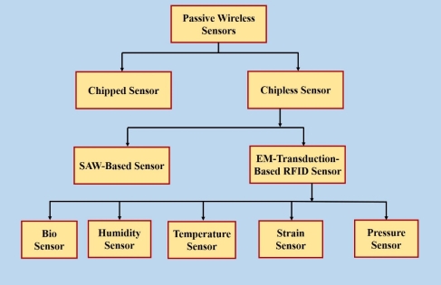
Fig.7 Chipless RFID Sensor classification
At the first instant, high frequency RFID technology at 13.56MHz and Ultra High Frequency RFID at 860 MHz t0 960 MHz are investigated in [51]. An epidermal sensor has been constructed using multi turn coils and reader is placed very close to the skin. Similarly, slot dipole antenna and Dual Square loop antenna are used for Ultra High Frequency epidermal system.
It is noticed that Ultra high frequency antennas provide good read range up to 1m or more. This performance of UHF antennas can be used in public places like, hospitals, airports and smart homes.
A wireless network which communicates among various sensors and working on very near to the human body is known as a Wireless Body Area Network or WBAN. This network has been a good demand in day-to-day usage like, sports, entertainment and in biomedical applications. In order to design the network, we have to take care of the size and weight of the device, which will be placed on the body. A new technology may be incorporated with the network i.e, wearable technology for more benefits of the human being.
Most importantly, total power consumption of the sensors is a big concern. Small and low profile radiators are very much useful for WBAN and wearable tag design applications [57-61].
The periodic structures, which can be used for microwave devices, radars, satellites etc, are known as frequency Selective surfaces or FSS. FSS uses Electronic Band Gap (EBG) and magnetic conducting artificial materials to decrease the antenna height and can be used in wearable systems. In [64], switching devices like PIN diode, varactor diode, Micro Electromechanical system etc are embedded with FSS in order to vary the operating frequency [70].
7.1 Design and measurement of tags at 2.4GHz and 5.8GHz
Since long, biomedical systems are, monitored wirelessly for easy diagnosis. The technique helps a patient in diagnosis and treatment without going to the hospital. [71].
Wireless monitoring system has the possibilities to treat a patient remotely through tele conferencing or video conferencing [72]. Many ECG monitoring wireless systems have been proposed [73–76]. Here, the main interface device is Bluetooth, which will communicate in between handheld device and ECG sensors. Wireless monitoring system is used to transmit biomedical data through by Bluetooth and is reported Baker et al. [77]. Other possible transmission system like ZigBee [21, 78] can be introduced to improve the existing system. Similarly, transmission of biomedical data is also possible using ZigBee network.
Microstrip planar antenna designs are available in many geometrical forms viz. rectangular, triangular and circular. Rectangular, square, circular. The strip shaped patches are the commonly used due to their easy analysis and fabrication. The physical parameters such as dimension of the patch, the height of the substrate, and dielectric permittivity etc. have important roles on antenna performances. They are dependent on antenna structures. Normally, low dielectric permittivity and high substrate height are preferred in order to achieve larger bandwidth, better radiation performance and efficiency [24]. However, low substrate height with high dielectric permittivity patch antenna is useful for the WBAN applications. It is due to the minimization of the transducers and avoidance of undesired radiation and coupling. Therefore, there is a trade-off between patch shape and the selection of materials and its performance in WBAN applications. Authors chosen a circular shaped microstrip antenna structure and a substrate with low relative permittivity for the development of a tag.
Feeding techniques are the most essential consideration for matching of input impedance of the patch antenna. Many feeding techniques are available in literature. The coaxial feeding, a probe feeds from the ground plane of the patch (also called back feeding), Microstrip line feeding, aperture coupling feeding, and proximity coupling, Coplanar wave guide feeding are mostly used.
7.1.1Circular Microstrip antenna Design:
According to the design consideration and Cavity Model Analysis [24], resonance frequency can be given by equation (11)
fr(mn0)=12πμϵχmn’a
(11)
The effective radius is given in (12)
ae=a1+2hπaεrlnπa2h+1.77261/2
(12)
Now applying the first-order approximation, (11) and (12) give the expression for the radius is shown in (13)
a=F1+2hπFεrlnπF2h+1.77261/2
(13)
Where
F=8.791×10⁹frεr
(14)
In equations (13) and (14), ‘h’ and ‘a’ must be in cm [1].
The authors designed a circular shaped microstrip antenna considering all the requirements of antenna parameters. ISM band is considered for design frequency of operation. . As per the Australian regulatory body, 2.45GHz and 5.8 GHz are considered as the resonant frequencies. Distance between transmitting and receiving antennas are chosen as 0.5–2 m, which will be good approximation for breathing monitoring in case of sleep apnoea application. The signal bandwidth is around 200 Hz that is adequate for back feeding technique. The 50 Ω SMA connector is attached at the feed point on the radiating patch for impedance matching purpose.
7.1.2Simulation and experimental results
A circular shaped microstrip antenna is simulated and designed considering moderately low dielectric substrate (Taconic TLX-0), dielectric permittivity
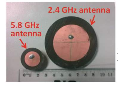
(ϵr)= 2.45 and operating frequencies, 2.4GHz and 5.8 GHz.
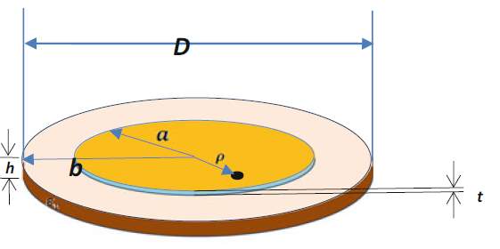
The design parameters are shown in table1. The geometric structure and prototype of the proposed microstrip antenna are shown in Figure 8. The Finite Integration Technique based CST Microwave Studio™ Electromagnetic Software is used to simulate the microstrip antenna. The height of the substrate is chosen as 0.7874 mm and listed in Table1. The probe diameter of coaxial feed is taken as 1mm and is connected to a SMA connector. The CST Microwave Studio™ software installed in a workstation which took 10hours to simulate the structure.
(a) (b)
Fig.8 Circular shaped microstrip antenna prototype (a) prototype antenna dimensions (b) antenna prototypes
Table 1. Design parameters of proposed microstrip antennas
| Design parameters | 2.4GHz Circular patch (mm) | 5.8GHz Circular patch at (mm) |
| D | 65 | 27 |
| a | 22.54 | 9.23 |
| b | 32.5 | 13.5 |
| ρ | 7 | 3 |
| h | 0.787 | 0.787 |
| t | 0.0017 | 0.0017 |
| ℇr (Taconic TLX-0) | 2.45 |
The simulation and experimental reflection coefficient and peak gain in dBi of circular shaped antenna at 2.4GHz are shown in Figure 9. Here, simulated performance of reflection coefficient of −13.5 dB, which resonates at 2.4325 GHz. The experimental reflection coefficient results are matching with simulation results. The measurement is taken in an Agilent make Vector Network Analyser (PNA E8361A). The peak realized gain of the proposed antenna is found to be more than 5 dBi.
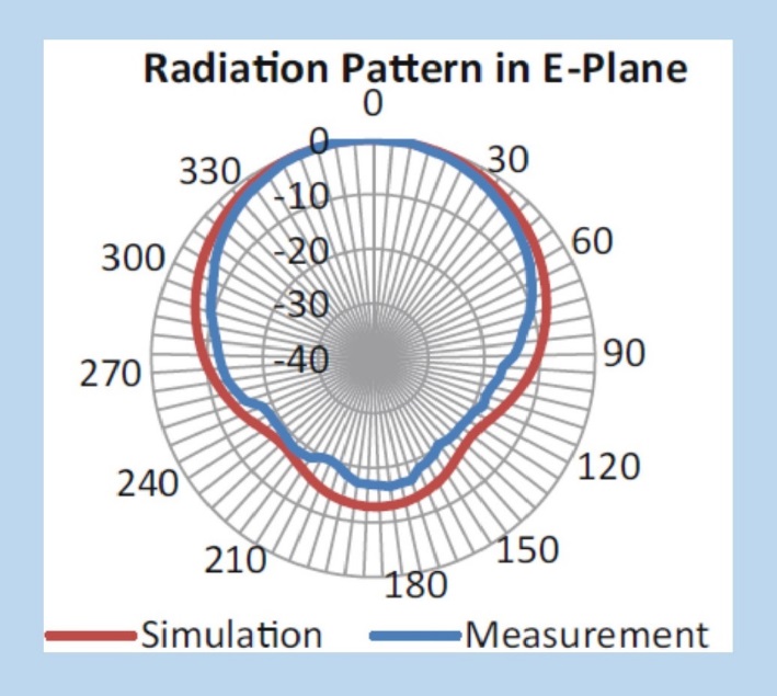
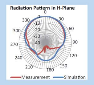
Figure 10presents the simulation and experimental radiation performances in E and H-planes respectively. The 3-dB beamwidth of nearly 70° with F/B of 15 dB are achieved. The peak gain is found approximately 5.6dBi through experimental verification. This proposed antenna is suitable for the application of wider Body Area Network as it achieves broad beamwidth and good peak gain.
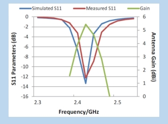
Fig. 9 Antenna gain and reflection coefficient of 2.43 GHz
(a) (b)
Fig.10 Radiation performance of the 2.43 GHz proposed antenna (a) E-plane and (b) H-plane
7.1.3Circular Microstrip Antenna at 5.8 GHz:
The simulation and experimental reflection coefficients and peak gain in dBi of 5.8 GHz circular shaped Microstrip antenna are shown in Figure 11. The simulated performance of reflection coefficient of −20.5 dB, which resonates at 5.84 GHz. The experimental reflection coefficient results match with the simulation results. The measurement of reflection coefficients are taken using Agilent vector network analyser (PNA E8361A). The peak realised gain of the proposed antenna is found to be more than 9.5 dBi. The experimental results for reflection coefficient of Microstrip patch antenna confirms that the antenna has resonance frequency of 5.79 GHz with a frequency shift of 50 MHz with respect to simulation result. The proposed antenna provides good peak gain in the range from 7.5 dBi to 9.5 dBi in the band 5.7GHz to 5.9 GHz.
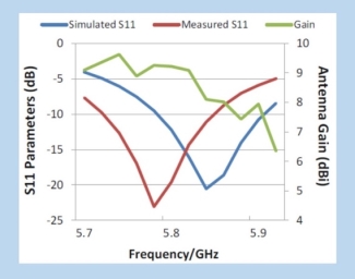
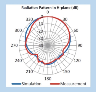
Fig. 11 Antenna gain and reflection coefficient of 5.8 GHz
(a) (b)
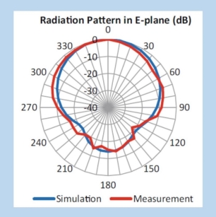
Fig.12 Radiation performance of the circular shaped Microstrip antenna 5.8 GHz (a) E-plane (b) H-plane
Figures 12 presents the simulation and experimental radiation patterns in E-plane and H-plane respectively. The 3-dB beamwidth is found nearly 60° with F/B ratio of 14 dB. As per the results discussed above, it is clear that circular shaped microstrip antenna designed at 2.43 GHz shows narrow bandwidth in comparision to the antenna designed at 5.8 GHz. Further, the circular shaped antenna designed at 5.8 GHz offers very good performance in terms of peak gain and reflection coefficient.
8. Propagation Performance of the 5.8 GHz band in WBAN Environment
The performances of two antennas at 2.4 and 5.8 GHz have been discussed in terms of reflection coefficient, input impedance, peak gain and radiation performances in the previous section. This section throws light on performance issues of this Microwave signal at 5.8 GHz band. Many wireless applications are found at 2.4 GHz, which is one of the useful ISM bands. Further, 2.4 GHz band is congested due to many wireless applications viz, WLAN, WiMAX, Bluetooth and Zigbee etc in this band. At the same time, 5.8GHZ channel is comparatively free with respect to 2.4 GHz band. The transmission system at 5.8 GHz can rectify the above problem with wireless systems using WLAN, WiMAX, Bluetooth and Zigbee etc. The size of the antenna is found to be compact at 5.8 GHz band which is useful for breathing monitoring system hence it is another noticeable advantage of using 5.8 GHz band.
Experimental Results
Five different reflection coefficient (S11 in dB) curves are shown in Figure 13, which are very near to each other. The circular shaped microstrip antenna at 5.8 GHz provides reflection coefficient of -19.6dB at 5.74GHz with a bandwidth (S11 < −10 dB) of 23% using free space measurement system.
As is shown in Fig. 13, the resonance frequency is moved around 300 MHz below at 5.71GHz with a better reflection coefficient of -23 dB whereas the measured reflection coefficient of -22 dB is achieved at 5.76 GHz in case of a cardboard cover condition.
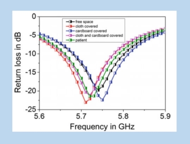
Fig. 13 Reflection coefficients of the microstrip antenna at 5.8 GHz in different environments
The experimental test with patient is similar as the cases of cloth and cardboard covers. The experimental results show that the bandwidth is around 130MHz that is 10MHz more than the previous one. The above discussion confirms that the design antenna at 5.8GHz maintains excellent performance throughout the breathing monitoring environment.
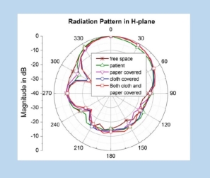
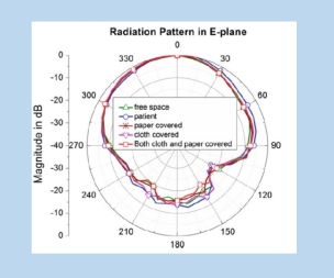
(a) (b)
Fig. 14 Radiation performance of the circular shaped microstrip antenna at 5.8 GHz (a) E-plane (b) H-plane
Figure 14(a) shows the normalized radiation performances the in E-plane. From the plot, it is clear that the 3-dB beamwidth is around 70° with F/B of 14 dB. Similarly, the normalized H-plane patterns shown in Figure14 (b) considering five separate environments. The patterns show a 3-dB beamwidth of 600 with F/B of 14dB that are nearly matching with free space setup.
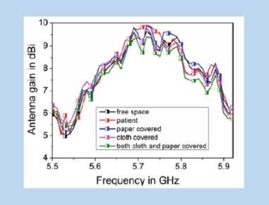
Fig. 15 Peak gain of circular shaped antenna tag at 5.8 GHz in five different environments
The proposed antenna gain is verified using Friis equation for transmission. The gain of the proposed antenna in five different environments are plotted and shown in Fig. 15. The fabricated antenna produced a peak gain of 9.9dBi with 2.43% bandwidth. This circular shaped microstrip antenna depicts a good penetrating performance that is suitable for breathing monitoring applications.
9.Conclusions and future work
This article has thrown light on few attributes of chipless RFID systems and its applications in Wearable Biomedical devices. The challenges in RFID tag design and tag design considerations are discussed in a nutshell. The antenna RCS design techniques for Chipless RFID as well as Friis transmission equation are discussed in detail in this article. The RCS of a chipless tag consists of two components. The structuralmode RCS is more powerful than the antenna mode. Thus, it is confusing to understand that the data information exists only in the structural mode RCS. It is clear from the discussion that the antenna mode RCS holds the real data bit information of the tag. Significant tag antenna parameters such as antenna effective area and RCS have been presented in order to highlight the different tag antenna designs. This review reveals that the two designs must be looked at from different viewpoints, while antenna effective area is the main consideration for the retransmission tag, for the backscattered tag.
The design, simulation and measurement of the planar circular shaped microstrip antenna on a good substrate with dielectric permitivity,
ϵr=2.45at 2.43 and 5.8 GHz have been analysed. It found that circular patch antenna could be preferred for wearable systems in various environmental conditions. The most important aspect is to choose proper dielectric material and structure of the design antenna. These two aspects are also important for designing antennas in breathing monitoring system. The systematic design procedure of the circular shaped microstrip antenna alongwith prototype development has been reviewed in this article. The different antenna parameters of the design results such as reflection coefficient, gain, radiation patterns have been discussed. The verification of antenna performance for various environmental conditions is a new direction of this article. It is clear that the proposed antennas easily overcome the propagation test in different wearable conditions and takeout the fear factor for the designer to incorporate the microstrip antenna in breathing monitoring as well as other related applications. Finally, various shaped patch antennas will be considered taking fractal geometries, EBG material, Metamaterials etc to design chipless RFID system for biomedical applications in future.
References
- Paris Kitsos and Yan Zhang, RFID Security Techniques, Protocols and System-on-Chip Design, pp 3-26, Springer. New York, 2008.
- S. Preradovic and N. C. Karmakar, “RFID readers-review and design,” in Handbook of Smart Antennas for RFID Systems, N. C. Karmakar, Ed. Hoboken, NJ: Wiley, 2010, p. 101.
- N. C. Karmakar, Ed. Handbook of Smart Antennas for RFID Systems, Hoboken, NJ: Wiley, 2010.
- M. A. Islam and N. C. Karmakar, “A novel compact printable dual polarized chipless RFID system,” IEEE Trans. Microwave Theory Tech.,vol. 60, no. 7, pp. 2142–2151, 2012.
- R. R. Fletcher, “Low-cost electromagnetic tagging: Design and implementation,” Ph.D. dissertation, School of Architecture and Planning, Massachusetts Inst. Technology, Cambridge, MA, 2002.
- Shuvashis Dey, Jhantu Kumar Saha, and Nemai Chandra Karmakar, “Smart Sensing: Chipless RFID Solutions for the Internet of Everything”, IEEE Microwave Magazine, ear: 2015, Volume: 16, Issue: 10, Pages: 26 – 39.
- N. C. Karmakar, R. V. Koswatta, P. Kalansuriya, and R. E. Azim,“Chipless RFID system operating principles,” in Chipless RFID Reader Architecture, Norwood, MA: Artech House, 2013.
- Nemai C Karmakar. “Tag, you’re It- Radar Cross Section of Chipless RFID Tags” IEEE Microwave Magazine Year: 2016, Volume: 17, Issue: 7 Pages: 64 – 74.
- N. C. Karmakar, R. V. Koswatta, P. Kalansuriya, and R. E. Azim,“Chipless RFID system operating principles,” in Chipless RFID Reader Architecture, Norwood, MA: Artech House, 2013.
- S. Preradovic, I. Balbin, N. C. Karmakar, and G. F. Swiegers, “Multi resonator-based chipless RFID system for low-cost item tracking,” IEEE Trans. Microwave Theory Tech., vol. 57, no. 5, pp. 1411–1419, Apr.2009.
- M. Zomorrodi, N. C. Karmakar, and S. G. Bansal, “Introduction of electromagnetic image-based chipless RFID system,” in Proc. IEEE8th Int. Conf. Intelligent Sensors, Sensor Networks and Information Processing, Melbourne, Victoria, Australia, 2013, pp. 443–448.
- R. E. A. Anee and N. C. Karmakar, “Efficient collision detection method in chipless RFID systems,” in Proc.7th Int. Conf. Electrical and Computer Engineering, Dhaka, Bangladesh, 2012,pp. 830–833.
- R. E. Azim and N. Karmakar, “A collision avoidance methodology for chipless RFID tags,” in Proc. Asia-Pacific Microwave Conf., Melbourne, VIC, 2011, pp. 1514–1517.
- Schueler, M., Mandel, C., Puentes, M. and Jakoby, R., “Metamaterial Inspired Microwave Sensors”, Microwave Magazine, IEEE, vol. 13, pp. 57-68, 2012.
- Shrestha, S., Balachandran, M., Agarwal, M. Phoha, V. V. and Varahramyan, K. , “A Chipless RFID Sensor System for Cyber Centric Monitoring Applications”, Microwave Theory and Techniques, IEEE Trans. on, vol. 57, pp. 1303-1309.
- Amin, E. M. & Karmakar, N. C., “Development of a low cost printable humidity sensor for chipless RFID technology, RFID-TA”, IEEE International Conference, pp. 165-170.
- Randika Koswatta; Nemai C. Karmakar, “Development of digital control section of RFID reader for multi-bit chipless RFID tag reading”, International Conference on Electrical & Computer Engineering (ICECE 2010) Year: 2010 Pages: 554 – 557.
- Nemai Chandra Karmakar, Yang Yang and Abdur Rahim (2018), Microwave Sleep Apnoea Monitoring, pp. 79-98, Springer, Singapore.
- K. Finkenzeller, RFID Handbook, 2nd edition, John Wiley & Sons, Hoboken, NJ, 2003.
- C. A. Balanis, Antenna Theory Analysis and Design, 3rd ed. Hoboken, NJ: Wiley, 2005.
- R. V. Koswatta and N. C. Karmakar, “A novel reader architecture based on UWB chirp signal interrogation for multiresonator-basedchipless RFID tag reading,” IEEE Trans. Microwave Theory Tech., vol.60, pp. 2925–2933, 2012.
- H. Mirza, M. I. Ahmed, and M. F. Elahi, “Circularly polarized compact passive RFID tag antenna,” in Proc. 5th Int. Conf. Electrical and Computer Engineering, Dhaka, Bangladesh, 2008, pp. 760–763.
- N. C. Karmakar, Koswatta, R. V., Kalansuriya, and P. R. E-Azim, Chipless RFID Reader Architecture. Boston, MA: Artech House, 2013.
- R. V. Koswatta and N. C. Karmakar, “A novel reader architecture based on UWB chirp signal interrogation for multi resonator based chipless RFID tag reading,” IEEE Trans. Microwave Theory Tech., vol. 60, no. 9, pp. 2925–2933, Apr. 2012.
- Merrill I Skolnik, Radar Handbook, Third Edition, McGraw-Hill Education, 2008.
- C. Occhiuzzi, C. Paggi, and G. Marrocco, “Passive RFID strain-sensor based on meander-line antennas,” IEEE Trans. Antennas Propag., vol.59, no. 12, pp. 4836–4840, 2011.
- Damiano Patron, “On the Use of Knitted Antennas and Inductively Coupled RFID Tags for Wearable Applications”, IEEE Transactions on Biomedical Circuits And Systems, Vol. 10, No. 6, December 2016
- L. Atzori, A. Iera, and G. Morabito, “The Internet of Things: A survey,”Comput. Netw., vol. 54, no. 15, pp. 2787–2805, Oct. 2010.
- J. Bito et al., “Inkjet-/3D-/4D-printed autonomous wearable RF modules for biomonitoring, positioning and sensing applications,” Proc. SPIE,vol. 10194, p. 101940Z, May 2017.
- Tong-Hong Lin, “On-Body Long-Range Wireless Backscattering Sensing System Using Inkjet-/3-D-Printed Flexible Ambient RF Energy Harvesters Capable of Simultaneous DC and Harmonics Generation”, IEEE Transactions on Microwave Theory And Techniques, Vol. 65, No. 12,pp.5489-5400, December 2017.
- S. Milici, S. Amendola, A. Bianco, and G. Marrocco, “Epidermal RFID passive sensor for body temperature measurements,” presented at the IEEE RFID-TA Conf., Tampere, Finland, Sep. 2014, pp. 8–9.
- E. Montón et al., “Body area network for wireless patient monitoring,”IET Commun., vol. 2, no. 2, pp. 215–222, Feb. 2008.
- A. A. Serra, P. Nepa, G. Manara, and P. S. Hall, “Diversity measurements for on-body communication systems,” IEEE Antennas Wireless Propag. Lett, vol. 6, pp. 361–363, 2007.
- B. A. Munk, Frequency Selective Surfaces: Theory and Design. New York, NY, USA: Wiley, 2005.
- J. C. Vardaxoglou, “Optical switching of frequency selective surface band pass response,” Electron. Lett. vol. 32, no. 25, pp. 2345–2346, Dec. 1996.
- Javier Lorenzo, “Modulated Frequency Selective Surfaces for Wearable RFID and Sensor Applications”, IEEE Transactions on Antennas and Propagation, Vol. 64, No. 10, pp.4447-4456, October 2016.
- V.M. Lubecke, O. Borić-Lubecke, Wireless technologies in sleep monitoring, in Radio and Wireless Symposium, RWS 2009, pp. 135–138 (2009).
- M.G. Martini, Wireless broadband multimedia health services: current status and emerging concepts, in IEEE 19th International Symposium on Personal, Indoor and Mobile Radio Communications, 2008, PIMRC 2008, pp. 1–6 (2008).
Cite This Work
To export a reference to this article please select a referencing stye below:
Related Services
View allRelated Content
All TagsContent relating to: "Medical Technology"
Medical Technology is used to enhance the medical care and treatment that patients are given in healthcare settings. Medical Technology can be used to identify, diagnose and treat medical conditions and illnesses.
Related Articles
DMCA / Removal Request
If you are the original writer of this dissertation and no longer wish to have your work published on the UKDiss.com website then please:


