Electrodeposition of Iron and Iron Co-deposits from DES
Info: 17825 words (71 pages) Dissertation
Published: 27th Jan 2022
Tagged: Chemistry
Abstract
The electrodeposition of iron co-deposited with Nickel and Cobalt from the deep eutectic solvents (DESs) ethaline and reline; mixtures of choline chloride and ethylene glycol, and choline chloride and urea respectively in a 2:1 ratio. The use of constant current plating technique with FeCl3 has been found to produce homogenous, dense and grey matt iron deposits. However, there are possible areas to be considered such as; concentration of metals, voltage used for electroplating, what would be the best DES to use, what combination of metal salts provided the best possible deposition.
The composition, morphology and grain size of the deposits are examined by scanning electron microscopy and the deposit thickness is characterised by Atomic force microscopy. It is found that the electro crystallisation process of nickel, cobalt and iron are all sensitive to organic additives in nature- such as saccharin and coumarin.
Experimental results determined that the best Ni-Fe-Co plates form at 2.5v, 60OC with a plating time dependant on the thickness of the plate required- A 60-minute plate produced a 57nm film whilst a 150-minute plate formed a 192nm plate- using ethaline as a medium. Results gathered from reline were not as successful and homogenous, dense and grey matt deposits were unable to be obtained.
Contents
Click to expand Contents
1. Introduction
1.1. Old electroplating methods
1.1.1. Ferrous sulphate bath
1.1.2. Ferrous chloride baths
1.1.3. Fluoborate bath
2. Literature review
3. Methodology
3.1. Preparation of DES
3.2. Preparation of the Substrate
3.3. Electroplating
3.4. Cyclic Voltammetry
3.5. Plate Analysis and Composition
4. Results and Discussion
4.1. Effect of DES on electroplating
4.2. Effect of Substrate on electroplating
4.3. Effect of Additives on Electroplating
4.4. Effect of Temperature on Electroplating
4.5. Effect of Voltage on Electroplating
4.6. Effect of Time on Electroplating
4.7. Cyclic Voltammetry
5. Conclusion
References
Appendix
1. Introduction
Electrodeposition of Fe films from aqueous electrolytes has been studied extensively [1] and has been used in industry for several years with applications such as the electroforming iron sheets and tubes, the repair of worn parts, [2] as well in the electronic industry due to the desirable physical properties of iron and its low cost.
The magnetic properties which can be obtained from electrolytic iron led to its use by the Western Electric Company in the cores of Pupin induction coils- Pupin coils prevented signal distortion in long distance telegraph transmission cables in the 19th century- preceding the development of nickel–iron alloys that have better magnetic properties. [3] However older methods of iron plating have become redundant as cheaper, safer [4] and more efficient methods of electrodeposition are needed due to poor current efficiencies, hydrogen embrittlement, toxicity of compounds involved and solubility of metal salts. Deep eutectic solvents (DES) provide one answer.
DESs and ionic liquids (IL) are two terms which have been used synonymously in the past, however, they are two different types of solvent. DES systems are formed from a eutectic mixture of Lewis or BrØnsted acids and bases which can contain a variety of anionic and/ or cationic species. In contrast ILs are systems formed primarily of one type of discrete anion and cation. Although the DESs and ILs share physical properties, the chemical properties suggest that the possible application areas may be significantly different. [5]
DESs contain large non-symmetric ions that have low lattice energy and low boiling points. DESs also have a wide electrochemical potential window, high ionic conductivity, high thermal stability and negligible vapour pressure which make them a great, cheap and safe medium for electroplating metal salts. [6-10] Whereas ILs are expensive to produce, have a low tolerance to moisture and some are toxic, they cannot all be used as a green media in electrodeposition. [11]
They are obtained by mixing a quaternary ammonium salt with a metal salt or Hydrogen bond donor. The charge delocalisation occurring through the hydrogen bonding between a halide ion and the hydrogen donor moiety is responsible for the decrease in melting point of the mixture relative to the melting point of the individual components respectively. [12, 13]
DESs have the general formula
Cat+X-zY
Where Cat+ is any ammonium, phosphonium or sulfonium cation, and X– is a Lewis base but generally a halide anion. Y is either a Lewis or BrØnsted which forms the complex anionic species with X–. z just refers to the number of Y molecules that interact with the anion.
Table 1: General formula for the classification of DES
| Type | General formula | Terms |
| Type I | Cat+X–zMClx | M=Zn, 1, 5, 6 Sn,7 Fe, Al,8 Ga,9 In10 |
| Type II | Cat+X–zMClx.yH2O | M=Cr,11 Co, Cu, Ni, Fe |
| Type III | Cat+X–zRZ | Z=CONH2,12 COOH,13 OH14 |
| Type IV | MClx+RZ=MClx=1+.RZ+MClx+1 | M=Al, Zn and Z=CONH2, OH |
DES can be classified depending on the complexing agent used. Type I Des are formed from MClx and quaternary ammonium salts, an example of a type I DES is the chloroaluminate/ imidazolium salt melt. [14] To overcome the shortcomings of Type I DESs- the lack of non- hydrated metal salts with low melting points- Hydrated metal halides were added to choline chloride to for they Type II DES. Type III deep eutectics, are formed from choline chloride and a hydrogen bond donor such as ethylene glycolor urea. [15] Type III deep eutectic systems can be used as a medium for many transition metal species, these liquids are simple to prepare, unreactive with water, biodegradable, and cheap. With the physical properties dependant on the hydrogen bond donor these liquids can be quite adaptable and altered for specific applications.
One of the earliest applications of DES was the electroplating of metals. [16] The process of electroplating leads to the formation of solid materials by an electrochemical reduction in the liquid phase. Electrodeposition has already been carried out in ionic liquids (IL). Compared to ILs DESs are cheaper to make, are less toxic and sometimes biodegradable. Therefore, DES can be used as safe, efficient, low cost solvents.
Electrodeposition is an electroplating process; it is analogous to a galvanic cell acting in reverse. When using DES the part which is plated is the cathode- copper or brass- of the cell alongside the anode- a dimensionally stable iridium oxide coated Ti mesh- both are immersed in the DES with metal ions already dissolved. A power supply applies a direct current to the cathode, the dissolved metal ions in the DES solution are reduced at the interface between the solution and the cathode, such that they “plate out” onto the cathode.
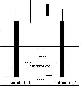
Figure 1: A Diagram of the basic electroplating process
Certain iron containing metal film- CoNiFe in particular- show higher saturation magnetisation [17, 18] values and are suitable for high frequency applications. However, this is dependent on the microstructure of the films as it is a soft magnetic material. Microstructure modification is a way to obtain desirable properties in soft ferromagnets. [19, 20]
Organic additives such as saccharin can be added to the DES to help obtain smaller grain size and reduce residual stress. [21] On the other hand, additives such as saccharin, prevent the formation of a passivated oxide layer at the surface, decreasing the corrosion resistance of the film. [22]
1.1. Old electroplating methods
The traditional electroplating industry for iron is based around three main bath types- the ferrous sulphate bath,ferrous chloride baths and the fluoborate bath, however there are others. [25, 26]
1.1.1. Ferrous sulphate bath
The Fe(II) (ferrous) produces the usual iron deposits- smooth, and light grey in colour. The iron films produced are resistant to corrosion- especially pitting, which is the creation of small holes in the metal.
Disadvantages of the ferrous sulphate bath are that it yields brittle deposits; the slow rate of deposition and the current density is roughly one half of that of a hot chloride bath. [23, 24] An advantage is that it can be operated at 25OC.
The most common sulphate bath is one which contains a double salt such as ferrous ammonium sulphate. However, Iron (II) sulphate may be used, either alone or with other salts such as sodium, magnesium or aluminium sulphate may be added. [25] The different added salts have minor specific effects of the properties of the precipitates and deposits. For example, the addition of a small amount of ammonium fluoborite to a high pH sulphate bath makes the slimy Fe(II) hydroxide precipitate that forms easier to filter off. [26] The presence of this ammonium ion reduces the rate of oxidation of the Fe(II) and the internal stress of the deposit.
Table 2 shows the two pH ranges for 25OC, these distinct pH ranges result from the different oxidation states of Fe- Fe(II) and Fe(III) with the foremost precipitating at a pH of about 6 and the latter precipitating at a pH of about 3.5. Even in the low pH range, in well reduced baths some Fe(III) is present due to air oxidation- reaction under nitrogen could prevent this. Operation too close to 3.5 would result in dark, excessively stressed deposits due to Fe(III) being deposited as well. In the higher pH range, 4.0- 5.5, a low concentration of Fe(III) is automatically maintained- the concentration maintained is equal to that of the solubility- as this is above the pH at which Fe (III) hydroxide precipitates. The higher pH sulphate bath has better covering power and yields deposits that are much less stressed compared to the deposits obtained in the low pH bath. With the internal stress generally increasing with increasing current density. [27]
At the higher operating temperature, oxidation of Fe is rapid at high pH. Hence only low pH range is viable. The advantage of an elevated operating temperature is the higher permissible current density. Any higher than 60OC the disadvantages outweigh any gain in permissible current density. Deposits from the sulphate bath do not become ductile at any temperature.
1.1.2. Ferrous chloride baths
The distinctive characteristics of a chloride bath is that they allow high current density, [23] fast deposition rates and the deposits formed are ductile when operated at temperatures higher than 85OC. The most commonly used bath of this type uses a solution of Fe(II) and calcium chlorides, which has been referred to as the Fisher- Langbein solution. [28] This bath yields dark, hard, highly stressed deposits at low temperatures, 25OC, at increasingly elevated temperatures, the deposits gradually become lighter.
The composition of the Fisher- Langbein solution as modified by Thomas and Blumand as modified for industrial use are shown in Table 2. [29, 30] The lower concentrations introduced by Thomas and Blum allow usage of moderate current densities and does not lead to crystallisation of salts when the bath is cooled. The calcium chloride present in the hot chloride bath increases the conductivity of the bath and cathode efficiency whilst leaving the deposit unaffected. [31] The importance of the hygroscopic character of calcium chloride in reducing evaporation of water from this type of bath and in raising boiling point seems to be a controversial, with some journals arguing that it is necessary and others say that the effects are overstressed. [26,27] However, the elimination of calcium chloride from the bath permits higher concentrations of ferrous chloride concentrations to be used. Thus, meaning higher current densities. For rapid deposition, a current density as high as 40 Adm-2 can be used with a ferrous chloride solution with a concentration of 120- 150 g L-1. [32] For lower stressed deposits, concentrations as high as 725 gL-1 FeCl2.4H2O have been used. [33]
Many modifications to the hot chloride bath have been described where the calcium chloride has been replaced by other alkaline earth chlorides. [25, 34] The presence of additives in these baths such as Mn(II) chloride has resulted in deposits with finer grain size, and a bath containing substantial amounts of this salt is recommended for machine part coating. [35, 36] Other additives to this bath are AlCl3, BeCl2 and CrCl2 which when added in low concentrations render deposits softer and increase ductility and stability. [37,38] Internal stress of the deposit increases with an increase of current density or with decreasing bath temperatures. The best deposits are obtained at elevated temperatures, with a low pH and high current density.
1.1.3. Fluoborate bath
The interest in producing deposits from a fluoborate bath grew when fluoroborate salts first became commercially available. Several baths have been described, but the conditions shown in Table 2 are recommended for general purpose baths. [39-43] A bath prepared with this method contains a small amount of fluoboric acid and boric acids, with boric acid having a desirable buffering action. The Fluoborate bath has great stability, high conductivity and a high tolerance to metal impurities. Disadvantages to this bath are that it is has a higher running cost than chloride or sulphate baths. The deposits are similar to those from the sulphate baths.
Table 1.1: Composition and operating Conditions for iron Plating Baths
| Type of Solution | Composition | Operating Conditions |
| Sulphate | FeSO4.(NH4)2SO4.6H2O:
250- 300 g L-1 FeSO4.7H2O: 250 g L-1 (NH4)2SO4: 120 g L-1 |
Low pH 2.8- 3.4 or high pH 4.0 -5.5, 2 Λ dm-2, 25OC
pH 2.1- 2.4, 4- 10 A dm-2, 60OC |
| For production of strip Chloride (Fisher- Langbein) | FeSO4.7H2O: 600 g L-1
FeCl2.4H2O: 300 g L-1 CaCl2:335 g L-1 FeCl2.4H2O: 300- 450 g L-1 CaCl2: 150- 190 g L-1 |
pH 1.4, 6.7 A dm-2, 47OC
pH 0.8-1.5, 6.5 Λ dm-2, 90OC pH 0.2- 1.8, 2- 9 Λ dm-2, 88- 99OC |
| For electrolyte | FeCl2.4H2O: 240 g L-1
KCl: 180 g L-1 |
pH 5- 5.5, 2-5 Λ dm-2, 25-40OC |
| For production of strip | Ferrous chloride
120- 150 g L-1 as Fe2+ |
pH 0.5- 4.7, 33- 40 Λ dm-2, 98- 106OC |
| Sulphate- chloride, for electrolyte | FeSO4.7H2O: 250 g L-1
FeCl2.4H2O: 42 g L-1 NH4Cl: 20 g L-1 |
pH 0.5- 4.7, 33- 40 Λ dm-2, 98-106OC |
| For production of strip | FeSO4.7H2O: 500 g L-1
NaCl: 50 g L-1 |
pH 3.5- 15, 3- 27.5 Λ dm-2, 80OC |
| Sulfamate | Iron(II) Sulfamate: 250 g L-1
Ammonium Sulfamate: 30 g L-1 |
pH 3.2- 15, 33- 40 Λ dm-2, 50- 70OC |
| Fluoborate | Fe(BF4)2: 226 g L-1
NaCl: 10 g L-1 |
pH 2– 3, 2– 10 Λ dm-2, 55– 60OC |
2. Literature review
2.1. Deep eutectic solvents: syntheses, properties and applications [15]
This paper investigates many diverse types of DES formed from choline chloride but varying the hydrogen bond donor and goes into detailed discussion about the many different industries that DES can be used in; catalysts, organic synthesis, green reaction media and the dissolution and separation of various compounds but the area of concentration is using DES for electrochemistry.
Electrodeposition is a process leading to the formation of solid materials by electrochemical reactions in a liquid phase. The setup is composed of a three-electrode electrochemical cell (a reference electrode, a specially designed cathode, and an anode or counter electrode).
Specifically, it lists ChCl/ urea, ChCl/ ethylene glycol and ChCl/ glycerol as the best for the electrodeposition of metals. This reinforces other papers as they all primarily use DES made for either ChCl/ urea or ChCl/ ethylene glycol. Many DESs can also selectively dissolve different metal oxides, which thus provide enormous potential for the selective recovery of pure metals, especially in electrochemistry. In the field of metal electrodeposition, similar results to those reported in conventional ILs were obtained in DESs.
2.2. Densities and refractive indices of the deep eutectic solvents (choline chloride + ethylene glycol) and their aqueous mixtures at the temperature ranging from 298.15 to 333.15K [11]
This paper set out to establish the physical properties of DES including density and refractive index. These could provide valuable information on the purity of a sample and the molecular interaction within the liquid.
Both DES were prepared in a 1:2 mol ratio of ChCl: urea and ChCl: ethylene glycol and then dried under vacuum at 333K for at least 48 hours to remove volatile impurities.
The densities were measured using an Anton Paar (model DMA 5000 M) vibrating tube density meter that has a measurement cell made of a U- shaped borosilicate glass tube and is equipped with two integrated Pt 100 platinum thermometers. To obtain maximum accuracy the measurements were obtained at higher temperatures.
The refractive indices of the systems were measured using as Anton Paar (model Abbemat WR) automatic refractometer utilising a yellow light beam of 589.3 nm sodium D line wavelength.
It was observed that the densities and refractive indices of the pure and aqueous mixtures decreased linearly with increasing temperature and mole fraction. This work shows that at higher temperatures the DES becomes less dense and allows mass transport at the cathode surface to take place faster.
2.3. Novel solvent properties of choline chloride/ urea mixtures. [12]
As the title of this paper suggests, the novel solvent properties of choline chloride/ urea mixtures are discussed. In addition, the paper defines what a Eutectic mixture is.
Ambient temperature molten salts have been formed by mixing quaternary ammonium salts with metal salts. This type of ionic liquid can be viewed as a deep eutectic resulting from the formation of complex anions thus decreasing the lattice energy and decreasing the freezing point of the system.
The paper shows that in the current work it is shown that mixtures of substituted quaternary ammonium salts such as hydroxyethyltrimethylammonium (choline) chloride with urea produce eutectics that are liquid at ambient temperature and have unusual solvent properties. A eutectic occurs at a urea to choline chloride ratio of 2:1. The freezing point of the eutectic mixture is 12 °C, which is considerably lower than that of either of the constituents- choline chloride = 302 °C and urea = 133 °C- and allows the mixture to be used as an ambient temperature solvent.
This significant depression of the freezing point must arise from an interaction between urea molecules and the chloride ion. This is consistent with the crystallographic data which shows extensive hydrogen bonding between the thiourea molecule and the oxalate anion. This Hydrogen bonding can be observed using NMR spectroscopy.
2.4. The influence of temperature on the efficiency of electroplating from various ionic liquids [59]
The purpose of this paper is to study the influence of temperature on the electroplating efficiency of various metals from ionic liquids.
Copper, silver, nickel and tin, in the form of metal chlorides, were dissolved in reline, ethaline and glyceline. After using a platinum rotating disc electrode, with an Ag/AgCl reference electrode, cyclic voltammetry to establish an optimum current density to electroplate each metal, basic electroplating processes were carried out at varying temperatures onto stainless steel. The mass deposited was used to calculate the efficiency of the process.
It was found that, generally, temperature influences the efficiency of electroplating from ionic solutions. While some solutions showed continuing improvements in plating efficiency as the temperature increased, others exhibited an optimum plating temperature. Copper solutions were best operated at an optimum temperature of 80OC, while the silver in reline solution was most efficient at 60OC. An optimum operating temperature of 80OC was also found for the tin solution of glyceline. Nickel in reline solutions must be used at elevated temperatures to form a certain complex before plating will occur.
The paper suggests that the conclusions drawn from the limited data obtained during a short, initial study of ionic liquids, and further work should be undertaken to obtain more detailed information, ideally using higher currents.
2.5. Natural deep eutectic solvents as new potential media for green technology [44]
This paper investigates using DES as new potential media for green technology.
The paper uses NMR spectroscopy to determine the structure of Many DES and identifies that the Hydrogen bonding present in all DES is what causes the eutectic effect of a lower freezing point as previously stated in “Novel solvent properties of choline chloride/ urea mixtures.”
The paper also investigates the physiochemical properties. Thermogravimetric analysis (TGA) was performed using, heating from room temperature to 100OC, kept at 100OC for 1 h, and then up to 300OC at a rate of 10OC min−1 in air. Differential scanning calorimetry (DSC) curve was recorded, from −120OC to 50OC at a rate of 10OC min−1 with heat down and heat up process in nitrogen. Density tests were performed using a density meter at 40OC. Viscosity test was performed using a viscometer, 40OC. Water activity test was performed in a water activity measurement equipment at 40OC. Polarity testing was done with Nile red (NR) as a solvatochromatic probe. The λmax was determined and used in the formula:
ENR (kcal mol-1) = hcλmaxNA= 28591/λmax
This investigation demonstrates that mixtures of many abundant primary metabolites from all kinds of organisms can form natural deep eutectic solvents (NADES) when mixed in adequate ratios.
2.6. Recent developments in deep eutectic solvents in chemical sciences [45]
This paper is similar to “Deep eutectic solvents: syntheses, properties and applications” as it describes all the possible DES that have been recorded, up to its publishing in 2013, and how to synthesise.
It also goes into detail about how DES is being researched in many different fields; electrochemistry, separation of materials, property, nanomaterials, analysis, chemical synthesis and biochemistry. This shows how DESs have a wide range of possible applications in chemistry.
The paper describes the physiochemical properties previously described in the other papers on DES referenced above. It also gives examples of different reactions that can be used as not only medium but also a catalyst for in organic synthesis such as the preparation α-mono- or α,α-dichloroketones at room temperature.
Both the common and uncommon properties of DESs have been extensively studied and have made them quite attractive “designer solvents,” and DESs can be prepared easily from low-cost and non-toxic chemicals.
Many applications of DESs have advantages in many areas of chemistry, such as; synthesis, electrodeposition, nanomaterials, biochemistry, separation, and analysis. Despite the wide range of developments in the study of DESs, many are still needed for further advancement. Their compositional flexibility can allow the preparation of new DESs, with different properties of DESs developed for novel applications.
2.7. Differential capacity of a deep eutectic solvent based on choline chloride and glycerol on solid electrodes [46]
This experiment used a different DES, glycerine, it was not used in the project, however it was another type with applications towards electroplating. Glycerine is made from a 2:1 molar mixture of glycerol to choline chloride at 700C.
The electrochemical experiments were conducted using a three-electrode water jacketed cell. The counter electrode was a glassy carbon rod and an Ag wire was used as a pseudo- reference electrode.
Cyclic voltammetry was carried out at 50 mVs-1 at a range of 50-10 kHz. Electrochemical impedance spectroscopy was also performed at the same range. Due to the capacitance calculation performed using the Nyquist plot equation:
C=y01n(1Rs)(n-1)/n
The CVs obtained showed no peaks, this meant there were no electrochemical impurities at any temperature. The curve of a DES depends on the solid electrodes material, the effect being larger for Au that for Pt. The values of C are within the range for DESs and show a similar shape dependence on the applied potential.
2.8. Iron plating [30]
This paper outlines operating conditions of traditional electroplating methods.
The most commonly used chloride bath is the ferrous chloride-calcium chloride solution. The deposits obtained from the chloride baths, if heat treated above 260OC, can be bent and formed a small amount. Most other solutions produce a deposit so brittle that it cannot be stressed without breaking.
The chloride bath, however, presents containment and environmental problems because of the elevated temperature, toxicity, and acidity of the solution. The advantages of this bath are its high conductivity high permissible current densities, fast plating rates, and relatively strong, ductile, smooth deposits.
Where plating speed is of no concern and lower operating temperatures are desired, the sulphate plating baths are suitable. The current density at which burning occurs is about one-half that of the chloride solutions. The sulphate is also not as soluble as the chloride. On the other hand, the sulphate solution can be operated at lower temperatures than the chloride solution.
The fluoborate bath solution has a high conductivity and good stability. The claim is made for higher current densities than the chloride solution at lower operating temperatures. The bath, in general, is similar to the others. The current efficiency drops with decreasing pH, the deposit is made brittle and stressed by organic contamination, and increased operating temperatures permit higher metal content and higher current densities.
The sulphamate bath is similar the sulphate bath but permits higher cathode current density. The typical characteristics of the deposit with respect to stress, hardness, and permissible current density are comparable those from other iron plating baths. Proprietary addition agents are available to reduce the stress and, as in other iron solutions, a wetting agent is recommended to eliminate pitting.
2.9. Electrodeposition of iron and iron alloys [27]
Similarly to “Iron plating”, this book chapter outlines traditional electroplating methods for iron as well as directions for maintaining the baths for optimum deposits.
The Ferrous sulphate bath produces deposits that are smooth and normally light grey in colour. There is little inclination toward pitting and thick deposits can be formed. Disadvantages of the bath are that the deposits are brittle, has a slow rate of deposition, and the current density at which burning occurs is about one-half that of a hot chloride bath. An advantage is that it can be operated at 25OC, in contrast with the ferrous chloride–calcium chloride bath which has much higher operating temperatures.
The distinctive characteristics of the chloride bath is that it permits high current density, fast deposition rates and when operated at temperatures higher than about 85OC yields ductile deposits. The most commonly used bath is a solution of Fe (II) and calcium chlorides, which has been named the Fischer–Langbein solution. This bath yields dark-coloured, hard, highly stressed deposits at 25OC. At increasingly higher temperatures, the deposits gradually become lighter in colour.
For a general-purpose bath iron plating from fluoborate solution is satisfactory. A bath prepared from the commercially available concentrated solution will contain a small excess of fluoboric and boric acids, which are present in the concentrate. The boric acid has a desirable buffering action. It is recommended that the concentration of boric acid is 18gL-1.
The fluoborate bath has high stability, high conductivity and high tolerance to metallic impurities. The disadvantage of the bath is that it is more expensive than the chloride or sulphate bath. The deposits yielded from a fluoborate bath are similar in brittleness and in most other properties to those from the sulphate bath.
Most of the references used in this paper are from the early to mid-1900s. So the information is quite outdated. However, the book specifies that some additives- Sodium lauryl sulphate- can be added to the baths as a suitable wetting agent.
2.10. Electroplating of Iron Films: Microstructural Effects of Alkaline Baths [4]
Several alkaline baths based on different complexing agents were examined for iron electroplating.
Chemically polished copper sheets (10mm × 10 mm) were used as cathodes. Polishing was carried out in a pickling solution containing 900 g/l H2SO4, 700 g/l HNO3 and 7 g/l NaCl at 20oC.
The resultant films were characterised by X-ray diffraction (XRD) and scanning electron microscopy (SEM). It was shown that adherent and smooth iron coatings with uniform microstructure can be obtained using alkaline Fe (II) baths containing pyrophosphate and tartrate ions as complexing agents.
Iron films with various microstructure can be produced in alkaline baths based on different complexing agents such as pyrophosphate, tartrate and EDTA. Pyrophosphate and tartrate Fe(II) electrolytes give adherent and smooth Fe films with fine grains and are characterised by a current efficiency up to 40-50%. In contrast, alkaline Fe(III) electrolytes containing EDTA produce rather coarse black coatings with columnar microcrystals and have a low current efficiency.
2.11. Electrodeposition of iron films from an ionic liquid (ChCl/urea/FeCl3 deep eutectic mixtures) [47]
In this paper, the electrodeposition of microcrystalline iron from an ionic liquid composed of choline chloride, urea and FeCl3 is demonstrated. The method employed is constant current plating, which is found to produce homogeneous, dense and grey matt iron deposits. The deposited iron films exhibited good corrosion resistance. Pure iron layers of up to 10 mm could be readily produced from the selected iron (III) electrolyte system.
Choline chloride and urea were mixed in a 1: 2 ratio. The ChCl/urea mixture was then processed under partial vacuum at 90OC for 3–4 hours to remove traces of ammonia and amines. Iron (III) chloride was used as received.
Successful electrodeposition of metallic Fe films onto copper substrate was obtained from the ChCl/urea/ FeCl3 mixtures. The use of constant current plating technique was found to produce homogeneous, uniform, dense, grey matt and pure iron coatings. Exposed to ambient atmosphere, the produced iron films showed no visible corrosion products on their surface after several weeks.
The surface morphology of the produced iron layers as a function of the applied current density was investigated. The electrodeposition of fine-grained and microcrystalline iron deposits free of defects was demonstrated using high resolution scanning electron microscopy (HRSEM) and energy dispersive X-ray spectroscopy (EDS).
2.12. On the electrodeposition of Nickel-Zinc alloys from a eutectic-based ionic liquid [48]
Electrodeposition of Zn-Ni alloys was investigated with reline being used as the DES.
The reline was prepared in a 2:1 molar ratio of urea to choline chloride at 70OC. Water content was measured using a Karl- Fisher titration and it was found that the DES contained 0.56% water. 0.1M of NiCl2 and 0.4M ZnCl were added to the reline and stirred until the DES became light green and homogenised.
Voltammetric data show that the reduction potential of Ni2+ is more positive than that of Zn2+, and Ni–Zn co-deposition was achieved through the deposition of Zn upon (deposited) Ni at a potential more negative than that of Ni deposition.
The alloy was plated onto Cu foil (10mm x 10mm) which served as the cathode. An Ag wire served as a reference electrode and a Ni plate was used for the anode. Deposition was performed at 70OC with a charge density of 7.2 C cm-2.
The surface morphology of the deposition was found to be heavily influenced by the deposition potential and the current density. Zn content was always less than 50% and there was always more Ni present. This was attributed to Zn being deposited onto the Ni.
It was shown that the Ni-Zn deposits containing above 87% Ni had a crack free structure, determined from SEM/ EDXS, XRD and potentiodynamic polarisation. Both this and the % deposition indicate towards the idea that Ni forms the deposition lattice and another metal, replaces Ni atoms in the lattice to form an alloy.
2.13. Tailoring nickel coatings via electrodeposition from a eutectic-based ionic liquid doped with nicotinic acid [49]
Reline was used in 1:2 ratio of ChCl–urea to electrodeposit pure Ni. Choline chloride and urea were mixed to form the reline at 750C, before NiCl2.6H2O and nicotinic acid (NA) were added. Finally, the solution was left to homogenise, which resulted in a bright green reline solution.
A 10mm x 10mm Cu substrate was used at the plating cathode with a copper wire with a diameter of 0.5mm was used as the anode. A Ni plate was used as a reference electrode.
It was found that without nicotinic acid, the Ni formed ‘pyramid like clusters’, ranging in size from 0.5 to 2.5 µm. This was expected due to the high rate of reduction of Ni (II) created by the reaction conditions.
The addition of NA significantly affected the reduction behaviour of Ni (II), the morphology and the microstructure of the Ni coating was investigated using electron microscopy and XRD. The NA imparts an inhibition effect upon Ni deposition, most likely related to the additive complexation and adsorption. It was shown that the electrodeposition of Ni proceeded via three-dimensional instantaneous nucleation/growth regardless of the concentration of NA.
The effect of NA translates to a very effective brightener, producing highly uniform and smooth Ni deposits related to the profound grain refining effect. This demonstrates that an additive used in aqueous baths translates to a DES bath. The surface morphology and grain size was highly dependent on the concentration of NA used and a grain size of 4.2 nm could be obtained with a concentration of 800 mg/L NA. By measuring the thickness of the coating, the current efficiency of the electrodeposition reaction was calculated at close to 100%.
Controlled functional additions of NA- and other additives- in trace amounts to DES such as reline can permit tailored coating characteristics, which has significant uses in practical and industrial applications.
2.14. Electrodeposition of Ni-Co-Sn alloy from choline chloride-based deep eutectic solvent and characterisation as cathode for hydrogen evolution in alkaline solution [50]
Electrodeposition of Ni-Sn, Co-Sn, and Ni-Co-Sn was carried out at Room temperature using ethaline (choline chloride and ethylene glycol, 1:2) as the solvent.
A 10mm x 10mm piece of Cu foil was used as the cathode and a 40mm x 40mm piece of Pt foil was used as the anode. The deposition took place at three different current densities, 30, 40, and 50 mA/cm2 to achieve a specific thickness of 10 µm.
Cyclic voltammetry measurements were taken for ethaline and each of the solutions used in the electroplating. SEM and XRD were used to measure deposit morphology and surface composition.
The crossover in the cathodic region of cyclicvotammetry indicates the alloy formation and there is no peak for individual elements. XRD analysis shows the binary and ternary alloy of Ni exhibits only the Ni lattice and the other elements are included in Ni lattice. It is further confirmed by SEM that binary and ternary alloys of Ni exhibit same morphology.
This is reinforced by the paper “On the electrodeposition of Nickel-Zinc alloys from a eutectic-based ionic liquid” which had the same results in that the Ni forms the deposition lattice and another metal, replaces Ni atoms in the lattice to form an alloy.
2.15. Electrodeposition of Co-Ni alloys [51]
Cobalt and nickel alloys were electrodeposited from an acid bath containing several different ratios of metallic cations. The effect of the plating variables on the composition and morphology of the deposits obtained on vitreous carbon electrodes was investigated.
For a fixed solution composition, the nickel content in the deposit is heightened by increasing the deposition potential. More homogeneous and fine-grained deposits can be obtained by increasing the cobalt(II)/nickel(II) ratio in solution and by ensuring that deposition takes place slowly. The solution must be stirred to keep the composition constant and to minimize the increase in local pH and to prevent hydroxide precipitation.
The results suggest the following sequence of events: first, Ni is deposited; then, Co adsorbs onto the freshly deposited nickel and begins to be deposited. The Co adsorption inhibits subsequent deposition of nickel, although it does not block it completely. Experiential data from “Electrodeposition of Ni-Co-Sn alloy from choline chloride-based deep eutectic solvent and characterisation as cathode for hydrogen evolution in alkaline solution” and “On the electrodeposition of Nickel-Zinc alloys from a eutectic-based ionic liquid” both supports this argument. If Fe is plated alongside Ni the same would happen as Co and Ni are iron group metals.
2.16. Synthesis and characterization of electrodeposited nanocrystalline nickel- iron alloys [52]
This paper investigated Nickel- iron nanocrystalline alloys with different compositions and grain sizes were fabricated by electrodeposition.
Various plating bath formulations were investigated. Each contained nickel sulfamate and iron chloride or iron sulphate as the metal salt. Nickel- iron FCC alloys with different compositions were deposited on copper substrates using a galvanostatic electrodeposition technique. The composition of the deposits was varied by changing the Ni/Fe ion ratio in the electrolyte and the cathode rotation speed.
Under similar deposition conditions, an increase in the iron content resulted in a significant grain refinement. Increasing the iron content beyond 21% did not decrease the grain size any further.
X-ray diffraction (XRD) analysis was applied to measure the lattice parameter, grain size and the level of internal strain of the deposits. The strength of the alloys was evaluated by microhardness testing.
The results of this study revealed that at a constant grain size of approximately 11 nm the hardness depends strongly on the iron content. The hardness showed a maximum around 20% Fe. The grain size of the alloys with 4- 6% iron was very sensitive to the deposition conditions. The hardness of these alloys followed the Hall- Petch relationship.
When the iron content of the deposits was increased beyond 35%, the internal stresses developed upon deposition were large enough to cause cracking. The microcracking pattern was dependent on the substrate, iron content and the crystal structure of the alloys.
2.17. Electrodeposition and properties of Ni- W, Fe- W and Fe- Ni- W amorphous alloys. A comparative study. [53]
Thin, micrometre-thick layers of a new amorphous alloy, Fe- Ni- W, have been obtained by electrodeposition.
Alloys with the iron mole fraction, exhibits the best properties under constant current deposition when it is approaching 1. However, properties for the other stoichiometries do not veer far from this.
FeFe+Ni=0.5→1
The key, needed properties of the Fe-W and Ni-W alloys were transferred to the Fe-Ni- W alloy, while the unwanted properties of the two-component alloys were eliminated. The new alloy is hard, smooth, of nice appearance, and of good adherence to both steel and copper.
SEM reveals that the internal structure and the surface smoothness of the alloys obtained under constant current conditions are not ideal. When using pulse deposition improvements start to show, especially in the texture of the alloy bulk which is somewhat grainy in the constant-current alloys, and in the surface smoothness. Pulse deposition allows for higher W content of up to 35%, this increase is achieved at a cost of Ni content in the deposit.
2.18. Effect of saccharin addition on the microstructure of electrodeposited Fe–36 wt.% Ni alloy [54]
Pulse current electrodeposition of Fe–36 wt.% Ni (Invar alloy) was carried out to investigate the effect of saccharin on the microstructure of the electrodeposited films.
Electrodeposition without saccharin gave burnt and torn deposits, due to the very high internal stress that developed during electrodeposition. However, with a saccharin concentration less than 3.0 g/L in electrolyte, the surface of the electrodeposit was smooth and bright with a uniform thickness. This corresponds with evidence from other papers “Electrodeposition of CoFe alloys in pulsed current electrolytes containing organic additives” and “Effects of saccharin and anions SO42-, Cl– on the electrodeposition of Co-Ni alloys” where the addition of saccharin reduced the stress of the co-deposit.
The deposits were composed of Face- centred cubic (FCC) and Body- centred cubic (BCC) mixed phases and an FCC phase having nanosize grains. With a saccharin concentration of more than 4.5 g/L, however, the surface became rough and dull with an appearance of faceted islands. This structure was related to the development of a fibre texture in the BCC phase. Based on TEM observation, it was found that some BCC grains grew to microsize, while the FCC grains remained as nanosized.
2.19. Effects of organic additives on electroplated iron-group metals and alloys. [55]
The objective of the study is also to investigate the effect of organic additives: saccharin (SAC), phthalimide (PHTA) and a new additive (OAS), on the electrochemical preparation of alloys composed of cobalt- iron.
To improve coating characteristics, several electroactive species can be added into electrolysis bath. Several studies have investigated the influence of organic additives in the plating bath. Some additives are known to enhance the morphology and physical properties of metal electrodeposits- Saccharin, thiourea and other compounds are commonly used as levelling and brightening agents in electroplating. Despite the widespread use of plating additives, the relationship between molecular structure and the final performance of additives for a deposited metal are not still completely known.
The sulphonamide group in saccharin could alter the deposition by including sulphur in the deposited metal. This was then compared to phthalimide, which differs from saccharin only by having a carbonyl group in place of saccharin’s sulphonamide group. OAS also shares a similar structure to saccharin but it contains a sulphonamide group. Therefore, OAS was also investigated to ensure it was the sulphonamide group that was having the effect on deposition.
XRD revealed that the roughness of the Co-Fe deposits decreased drastically with the addition of each additive- with saccharin having the greatest effect- dropping the Ra value from 262nm to 2 nm. The brightening effect of saccharin was attributed to this severe drop in roughness, although no link between the sulphonamide group and deposition was discussed.
2.20. Effects of saccharin and anions SO42-, Cl– on the electrodeposition of Co-Ni alloys [21]
This study focused on the effects of sulphate, chloride and saccharin on the electrodeposition of Co-Ni alloy films in synthetic solutions.
Na2SO4, NiSO4, NiCl2, CoSO4, and CoCl2 were all mixed with sodium saccharinate salt. A saturated HgSO4 electrode was used as the reference electrode, with a graphite bar as the counter electrode. A Cu rod embedded in nylon was the working electrode. All three electrodes were then mounted to a rotating disk. The deposition was carried out at room temperature with a charge density of 50 C.
The electrode responses during deposition provides evidence supporting findings from previous studies that saccharin adsorbs on the surface at potentials of approximately −1.0 V.
From analysis of the amount and composition of deposited metal, the main effect of this adsorption is to inhibit H2O reduction at higher over potentials, which thereby facilitates metal deposition and widens the potential and current ranges at which the electrodeposition of Co–Ni alloys can be effectively plated.
Regardless of the electrolyte and the presence saccharin, deposition follows anomalous behaviour at all current densities in every bath, although it approaches normal behaviour as the current density increases toward −1,000 A m−2 and Co(II) reduction becomes mass transfer controlled. The presence of saccharin tends to lower the Ni content and promote higher anomalous behaviour to a relatively small extent that remains essentially constant across a wide range of current densities from −100 to −1,000Am−2.
Higher deposition current efficiencies are achieved using a mixed sulphate chloride solution containing saccharin, than in a sulphate-only solution containing saccharin, a chloride-only solution containing saccharin or a sulphate-only solution containing no additive. Differences in the effect of the current density on the current efficiency are evident at intermediate-to-high overpotentials depending on the bath composition.
2.21. Electrodeposition of Cobalt- Iron alloys in pulsed current electrolytes containing organic additives [56]
This paper builds on the theory that sulphonamide groups in additives such as saccharin is the key to its additive effect and increases the deposits anti- corrosion properties.
CoFe thin films were electrodeposited with an approximate thickness of 2 µm on silicon wafers with a sputtered Permalloy (80 nm) interlayer. In addition, a sputtered chromium (20 nm) adhesion layer was deposited between Si and Ni–Fe.
Similarly, to the paper “Effects of organic additives on electroplated iron-group metals and alloys.” Pthalamide was used as it only differs from saccharin by having a carbonyl group in place of saccharin’s sulphonamide group. The corrosion properties of the deposit were determined by anodic polarization and the deposition morphology was studied using SEM.
Whilst both additives improved corrosion resistance of the Co- Fe co-deposit, saccharin reduced the activation more effectively than pthalamide. “Effects of organic additives on electroplated iron-group metals and alloys” reinforce these results, as Co- Fe deposited using pthalamide as an additive form clusters whilst those deposited with saccharin resulted in homogenised flat deposits.
This paper concluded that the sulphonamide group was responsible for the anti- corrosion and brightness properties of the Co-Fe deposit.
2.22. The influence of organic additives on the electrodeposition of iron-group metals and binary alloy from sulphate electrolyte [57]
Thin films of the iron-group metals Fe and Co and binary CoFe alloy are electroplated from an acid sulphate electrolyte onto a copper rotating disk electrode.
The partial current densities of the codepositing metals and of the side reaction in the presence of organic additives are determined from an analysis of the deposit, and is compared with those measured for the pure metals and those electroplated without additive.
Organic additives do not affect the CoFe deposition mechanism. However, SAC and PHTA decrease the rate of iron deposition contrary to o-toluene sulphonamide (oTOL).
The experimental results show that the cobalt and iron co- deposition mechanism which consists of two consecutive one-electron steps with an adsorbed intermediate are not changed by the presence of the organic additives- SAC, PHTA and oTOL.
2.23. Electrodeposition of Fe thin films on Si (1 1 1) surfaces in the presence of sodium saccharin [58]
In this paper, the fabrication of metallic Fe deposits onto Si (1 1 1) is described, using the potentiostatic electrodeposition technique.
The addition of sodium saccharin in the aqueous ammonium-sulphated solutions tends to inhibit the solid-state reaction between Fe and Si and enhance the protection against oxidation under air exposition compared to deposits without additive.
Sodium saccharin shows to be a levelling, brightening, and stress reducing agent capable to alter the ferromagnetic behaviour of the films at room temperature; alike saccharin and other additives in other papers referenced above. The influence of the additive on the surface morphology, crystalline structure, microchemistry, and magnetism of deposits is discussed.
All the electrodeposition experiments were performed at room temperature using a stationary three-electrode cell. The working electrodes were single-sided polished rectangular (4 mm × 5 mm) phosphorous-doped n-type Si (1 1 1) wafers. e. A standard saturated Ag/AgCl electrode was used as the reference electrode and a platinum disk was used as the counter electrode.
The surface morphology of the deposits was analysed by atomic force microscopy (AFM), with a scanning probe microscope. The X-ray diffraction (XRD) measurements were performed as well as X- ray photoelectron spectroscopy (XPS).
Excellent quality metallic Fe deposits were obtained. The film morphology, surface chemistry, structure, magnetic, and electronic properties were analysed by various techniques revealing that spontaneous reactions between Fe deposits and Si surface, have been inhibited by using sodium saccharin.
2.24. Electroplating and characterisation of Co-Ni-Fe and Ni-Fe for magnetic microsystems [17]
This paper contained detailed usage of pulse reversed and direct current electroplating to create magnetic microsystems from an electrolyte solution containing Co, Fe and Ni. A pulsed reversed plating method was used using a ferrite core with two coils to plate onto a wafer.
The second plating described was carried out using NiFe. A NiFe bath was used based on the design of a NiSO4 bath with had been widely described in previous journals. The NiFe was deposited at 28OC with a current density of 0.25- 1 A/ dm2 being used.
Using quantitive energy dispersive x-ray analysis concentrations of metals used shows far more Ni present than Fe or Co. This supports the conclusions of the paper “On the electrodeposition of Nickel-Zinc alloys from a eutectic-based ionic liquid” that Ni forms a lattice structure and other atoms replace Ni atoms.
In this paper, saccharin was also used as an additive. Whilst no further discussion was carried out, it presents further evidence to suggest that it can be used as an effective additive.
2.25. Magnetic properties of nanocrystalline iron group thin film alloys electrodeposited from sulphate and chloride baths [23]
Systematic studies of iron group binary (NiCo and CoFe) and ternary (CoNiFe) thin film alloys relating their magnetic properties with film composition, grain size and the corresponding crystal structure were investigated. Electrodeposited magnetic thin films of the iron group metals (Fe, Co and Ni) have been developed because of potential applications in computer read/write heads and microelectromechanical systems (MEMS).
Anions influence current efficiencies, magnetic properties, surface morphology and phases of electrodeposited films as stated in “Effects of saccharin and anions SO42-, Cl- on the electrodeposition of Co-Ni alloys.” Higher current efficiencies in chloride baths compared to sulphate baths were observed for CoFe, NiCo and CoNiFe alloys. The higher deposition current efficiencies in chloride baths were attributed to a catalytic effect.
Anion types in CoFe and CoNiFe thin film alloys influenced the microstructures and the resulting magnetic properties. However, the microstructures of NiCo alloys was dependant on the deposit of the Co contents rather than anion types.
The surface morphologies of CoFe, NiCo and CoNiFe thin films were independent of anion types. CoFe deposits displayed relatively smooth surface morphology and turned crystalline with increasing Fe+2 concentration. NiCo deposits showed very smooth surface morphology whilst CoNiFe deposits had the surface morphology of polyhedral crystallites. The Fe content in CoFe electrodeposits increased linearly with increasing solution Fe+2 concentration for both chloride and sulphate baths. Similar linear behaviour of deposit Co contents was observed in NiCo electrodeposits.
Saccharin was used as an additive to reduce the deposit stress.
3. Methodology
3.1. Preparation of DES
Choline chloride (Sigma- Aldrich, 98%) [ChCl] and ethylene glycol (Fluka, 99.5%) were mixed in a 1:2 molar ratio of Ch: Hydrogen bond donor. [33] The ChCl/ Ethylene glycol mixture was processed under atmospheric pressure at 60oC using a Corning PC-420D heating plate to allow the mixture to fully reach its eutectic point.
Choline chloride [ChCl] and urea (Acros, 99%) were mixed in a 1:2 molar ratio of Ch: Hydrogen bond donor. [33] The ChCl/ urea mixture was processed under atmospheric pressure at 60oC to allow the mixture to fully reach its eutectic point. It was imperative not to heat the Reline above 60oC to prevent the urea degenerating and ammonia being given off.
3.2. Preparation of the Substrate
Both copper and brass was used as a substrate. 5cm by 1cm strips were cut out using a 5” manual sheer. They were then rinsed with water, degreased in dichloromethane and dried with nitrogen. The plates were then stored away from any forms of grease as this can prevent deposition of metal.
Both Ethaline and Reline were made in bulk and stored in an oven set at 40oC to prevent the ChCl from crashing out. This just saved time at the beginning of every lab as it did not need to be made every day.
3.3. Electroplating
The iron (III) chloride (Sigma- Aldrich, 97%), iron (II) chloride (Sigma- Aldrich, 97%), hydrated iron (II) chloride (Sigma- Aldrich, 98%), cobalt (II) chloride (Sigma- Aldrich, 97%), hydrated cobalt (II) chloride (Sigma- Aldrich, 97%), hydrated cobalt (II) sulphate (Sigma- Aldrich, 95%), nickel (II) chloride (Sigma- Aldrich, 98%), Hydrated nickel (II) chloride (Sigma- Aldrich, 99.9%), Hydrated nickel (II) sulphate (Sigma- Aldrich, 99%) were used as received to prepare the electrolytes.
To begin with 0.3M solution were made using both Reline and ethaline. 20ml of a DES was poured into a glass sample vial, the 0.3M of a metal salt was then added. The cell was then placed on the hot plate and a magnetic flea was added to make sure that the metal salt completely dissolved into the DES.
The substrate was placed into the electrolytic cell along with the dimensionally stable iridium oxide coated Ti mesh anode. The cell was the placed in the Fisher scientific dray bath filled with sand- the temperature set was dependant on the conditions set for that plate- and connected to the EL302RD duel power supply. The Current was then set to maximum and the voltage could be varied depending on the deposition conditions.
After a set period of time- depending on the conditions- the power supply was then turned off and the electrodes disconnected. The substrate was then washed in acetone first and then water to remove all traces of the DES and prevent corrosion of the metal.
A range of factors were changed during the electroplating process to get the best deposition, such as; temperature, time, substrate, additives, voltage and the DES itself [48- 50].
3.4. Cyclic Voltammetry
Cyclic voltammetry was carried out using a laboratory potentiostat (Emstat2 Palm instruments BV) controlled by a PC (PSTrace). A three-electrode closed system consisted of a platinum wire counter electrode, a platinum working electrode and a silver reference electrode. The platinum working electrode was washed and then polished with alumina powder on a polishing cloth. It was then placed in a beaker of distilled water in a sonic bath for 5 minutes to clean any alumina off. Electrochemical measurements were all performed at 60OC. A scan rate of 0.1 V s-1 was used in all voltammetric experiments.
3.5. Plate Analysis and Composition
To carry out the plate analysis a SEM (Jeol JSM-7100f) was used in partnership with Energy-dispersive X-ray spectroscopy (Oxford instruments X-max detector) connected. The Atom Force Microscope used was a BRUKER Dimension Ion with Scan Asyst.
4. Results and Discussion
4.1. Effect of DES on electroplating
The effect of DES on the electroplating needed to be investigated to see initially how well and how well they dissolve the metal and additives. Also, the quality of the films deposited on a copper substrate over a 60-minute period at 60OC with 2.5Vs applied.
Table 4.1.: Effect of DES on electroplating
| Solution Composition | |||||
| Metal salt | Electrolyte | Additives | Substrate | Plate Description | Comments |
| FeCl3+ CoSO4.7H2O+
NiSO4.6H2O |
Ethaline | Saccharin | Copper |  |
Dull grey. Even coverage. No rusting. No holes |
| FeCl3+ CoSO4.7H2O+
NiSO4.6H2O |
Reline | Saccharin | Copper |  |
Not a consistent coverage. Rusting, Holes in the film. Black/ Blue/ Grey. |
From this experiment, ethaline is the better DES to use with such copious amounts of metal and additive going into it. Ethaline easily dissolved it all, whereas reline didn’t and formed a paste- after an hour this paste had separated out and the metal and additive was deposited onto the bottom of the glass vial.
The plating quality was also greater when using ethaline as a consistent coating was deposited onto the substrate and had a nice dull grey colour. Reline however had not covered enough of the substrate- most likely because most of the metal was deposited on the bottom and not in solution.
This result contradicts most of the journals- not on the fact that ethaline was the best to use, but that reline should have dissolved the Fe without a problem. But it struggled. This could be due to the 0.3M concentration used, but ethaline could dissolve higher concentrations before sediment appeared on the bottom.
However, in most papers reviewed reline is the preferred DES and provides the best plates. This didn’t work out in the plating. This could be due to the increased viscosity of reline in comparison to ethaline which would slow down mass transport. [49] Higher temperatures could solve this problem.
4.2. Effect of Substrate on electroplating
The effect of the substrates used is investigated here and how well the metal can deposit onto them. The two substrates used were copper and brass. A 60-minute period was used at 60OC with 2.5Vs applied like in the previous test.
Table 4.2.: Effect of Substrate on electroplating
| Solution Composition | |||||
| Metal salt | Electrolyte | Additives | Substrate | Plate Description | Comments |
| FeCl3+ CoSO4.7H2O+
NiSO4.6H2O |
Ethaline | Saccharin | Copper |  |
Dull grey. Even coverage. No rusting. No holes |
| FeCl3+ CoSO4.7H2O+
NiSO4.6H2O |
Ethaline | Saccharin | Brass |  |
Dull grey. Even coverage. No rusting. No holes |
There isn’t much difference between the iron films on the copper or brass substrate. Both have a dull grey colour, an even coverage. Neither show signs of rusting and there are no holes in the film where it didn’t plate. However, copper was chosen as the main substrate to be used as it didn’t bend as it was much more rigid than the brass and fit into the cells better.
From reviewing previous literature, Fe, Ni and Co can all be plated onto a variety of different substrates such as Si demonstrated by Zarpellon et al. [58]
4.3. Effect of Additives on Electroplating
There have been many studies on the effect of additives on the deposition of metal films [21, 54-57] and they all agree on the same thing: the addition of saccharin reduces the stress of the deposit and increases the deposits anti- corrosion properties. [56]
The voltage, Temperature and time was 3v, 50OC and 60min respectively as it was just iron that was being plated on its own.
Table 4.3.1.: Effect of Additives on Electroplating Coumarin
| Metal salt | Electrolyte | Additives | Substrate | Plate Description | Comments |
| FeCl3 | Ethaline | Coumarin | Copper |  |
The film was black before the Fe oxidised. However, during cleaning of the copper substrate and the film to get rid of excess DES most of the film came away from the substrate which is not a good sign. |
| FeCl3 | Ethaline | Coumarin | Brass |  |
The same thing happened with the brass substrate. The film was black before the Fe oxidised. However, during cleaning of the substrate and the film to get rid of excess DES most of the film came away from the substrate which is not a good sign. |
| FeCl3 | Reline | Coumarin | copper |  |
With Reline the coumarin improved the deposition of the Iron onto the substrate compared to electroplating with no additives. But a consistent iron film was not produced. |
| FeCl3 | Reline | Coumarin | Brass |  |
Not much iron was plated with both reline and coumarin. Any iron that was plated was washed off with the DES. |
Table 4.3.2.: Effect of Additives on Electroplating Saccharin
| Metal salt | Electrolyte | Additives | Substrate | Plate Description | Comments |
| FeCl3 | Ethaline | Saccharin | Copper |  |
This plate was by far the best out of all the plates that were run in this experiment. It was a dull black film. Even coverage and no holes. |
| FeCl3 | Ethaline | Saccharin | Brass |  |
This was also a good plate. Before it started to rust it was a black covering however there were holes in the film at the bottom. |
| FeCl3 | Reline | Saccharin | Copper |  |
This is the best reline plate of the set. However, the middle of the plate has some holes and it only plated on one side. |
| FeCl3 | Reline | Saccharin | Brass | 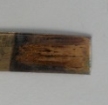 |
The film was very streaky and rusted. It was black and had holes in the film. |
The best additive was saccharin, this is because when coumarin was used the metal film fell off the substrate when the DES was washed off. Saccharin also worked best in both reline and ethaline, and the results were similar for copper and brass. However, brass was slightly better.
Initially only FeCl3 was added but after the electrodeposition had finished the iron deposit would quickly oxide in the atmosphere to form iron oxide. To try to overcome this problem both FeCl2 and FeCl2.4H2O were both trialled but the result was the same. It was at this point it was decided to concentrate on co depositing Fe with NI and Co. This provided much better deposits and there was no rusting henceforth.
There are many papers that support information gathered from this investigation. It has been suggested in paper by Lallemand et al. [55] that the sulphonamide group in saccharin could alter the deposition by including sulphur in the deposited metal. This has been compared to other additives such as pthalamide, which differs from saccharin only by having a carbonyl group in place of saccharin’s sulphonamide group and saccharin produced far better deposits.
As shown in previous literature by Kim et al. [54] addition of saccharin also leads to a deposit which is smooth and bright with uniform thickness. When the deposits were first removed from the DES and washed, the deposit was smooth and bright- until the iron on the surface started to oxidize in the atmosphere.
4.4. Effect of Temperature on Electroplating
This investigation was carried out to investigate the effect of temperature on the deposition of metal. As the temperature increases the DES becomes less dense allowing mass transport of the metal ions in the electrolyte solution to occur much faster. [11]
As per the other tests the DES used as a medium was ethaline with saccharin as an additive. The substrate that was used is copper, the voltage used was 3v and the plating time was 60 minutes.
Table 4.4.: Effect of Temperature on Electroplating
| Metal salt | Temp /oC | Plate Description | Comments |
| FeCl3+ CoSO4.7H2O+
NiSO4.6H2O |
40 |  |
Patchy coverage near the ends. Dull grey film. |
| FeCl3+ CoSO4.7H2O+
NiSO4.6H2O |
50 |  |
Consistent iron film coverage across the plate. Dull black in colour. Streaky in places. |
| FeCl3+ CoSO4.7H2O+
NiSO4.6H2O |
60 |  |
This was the best film. There were no holes or streaks. And it looked the same all over. The was a dull grey in colour (camera flash makes it look shiny) |
| FeCl3+ CoSO4.7H2O+
NiSO4.6H2O |
70 |  |
The outside of the plate is black whilst the inside is grey. This shows that more iron plated at the edges- probably due to the higher temperature. |
| FeCl3+ CoSO4.7H2O+
NiSO4.6H2O |
80 |  |
This plate is patchy grey and black- this is where different amounts of iron plated to various parts in a higher concentration then others. |
60OC was by far the best plate matching descriptions from Cleaves et al. as the plate was a dull grey colour and matching the description given by Kim et al. [54] addition of saccharin also leads to a deposit which is smooth and bright with uniform thickness.
A paper by Rasmussen et al. [17] reported temperatures as low as 28OC have been shown to successfully plate onto a substrate.
In Table 4.1. the DES reline wasn’t as effective as ethaline at depositing the metal- this could be since it has a higher density 1.25 g cm-3 compared to ethaline which has a density of 1.12 g cm-3. Therefore, at higher temperatures reline may provide the best deposits as suggested in the paper by Böck et al.
4.5. Effect of Voltage on Electroplating
When it was decided that a deposit consisting only of iron would be hard to analyse due to the extended period it would to be left out in the atmosphere that it would oxidize before it could be examined on the AFM or EDXS. Due to this it was time to move on to investigating co-deposits as it had been described in more recent literature. [52-55]
The substrate, temperature, time are copper, 60OC and 60 min respectively.
Table 4.5.: Effect of Voltage on Electroplating
| Metal salt | Electrolyte | Additives | Voltage /V | Plate Description | Comments |
| FeCl3+ CoSO4.7H2O+
NiSO4.6H2O |
Ethaline | Saccharin | 1 |  |
Not much plating happed- voltage was too low. |
| FeCl3+ CoSO4.7H2O+
NiSO4.6H2O |
Ethaline | Saccharin | 2 |  |
It is the correct dull light grey colour suggests that very little iron is being plated. |
| FeCl3+ CoSO4.7H2O+
NiSO4.6H2O |
Ethaline | Saccharin | 2.5 |  |
The dark grey colour is best as it contains iron but hasn’t rusted. |
| FeCl3+ CoSO4.7H2O+
NiSO4.6H2O |
Ethaline | Saccharin | 3 |  |
This plate is black and patchy. |
| FeCl3+ CoSO4.7H2O+
NiSO4.6H2O |
Ethaline | Saccharin | 4 |  |
The film that was produced is patchy- it is black on the outside and grey on the inside. |
| FeCl3+ CoSO4.7H2O+
NiSO4.6H2O |
Ethaline | Saccharin | 5 |  |
Thick black film was produced. However, as you can see it didn’t plate at the bottom. |
In conclusion, it was decided that 2.5v was the best voltage to use- this was due to Ni plating best at 2v and anything higher didn’t show signs of nickel, Fe plated at 3-3.5 and Co plated at a wide range of 2-4. 2.5 was the highest voltage that could be used that would produce a dark grey film that had been described by Cleaves et al. [25]
4.6. Effect of Time on Electroplating
To investigate how the plating time effected the deposit, AFM was used to determine the step height of the deposit, and the Roughness Average (Ra) and the root mean squared roughness (Rq).
The substrate, temperature, voltage is copper, 60OC and 2.5v respectively.
Table 10: Effect of Time on Electroplating
| Metal salt | Electrolyte | Additives | Time /min | Plate Description | Step height /nm | Ra | Rq | ||||
| FeCl3+ CoSO4.7H2O+
NiSO4.6H2O |
Ethaline | Saccharin | 30 |  |
29.1 | 18.6 | 23.5 | ||||
| FeCl3+ CoSO4.7H2O+
NiSO4.6H2O |
Ethaline | Saccharin | 60 |  |
57.0 | 182 | 136 | ||||
| FeCl3+ CoSO4.7H2O+
NiSO4.6H2O |
Ethaline | Saccharin | 90 |  |
– | 118 | 116 | ||||
| FeCl3+ CoSO4.7H2O+
NiSO4.6H2O |
Ethaline | Saccharin | 120 |  |
185 | 242 | 208 | ||||
| FeCl3+ CoSO4.7H2O+
NiSO4.6H2O |
Ethaline | Saccharin | 150 |  |
192 | 101 | 90 |
When the metal was left to deposit on the substrate for the shortest amount to time- 30 minutes- this deposit was the thinnest. 150mins was the thickest plate with a step height of 192nm. It may have been the thickest but it did start to turn blue. This is due to the iron plating the fastest and cobalt plating over the top.
The step height couldn’t be calculated at 90 minutes as the AFM couldn’t produce a clear micrograph.
From these results, it was decided that 1 hour plating time was long enough. Due the amount of plates that could be run at one time and with the considerable number of plated that needed to be deposited on, if longer than one hour was selected it would not have been possible to finish the project.
The step difference between 150min and 120min isn’t that great, this is probably reaching the max plate thickness that could be achieved.
4.6.1. Atomic Force Microscopy
A 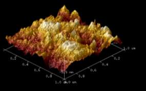
B 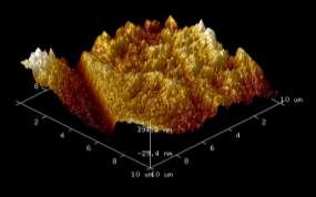
C 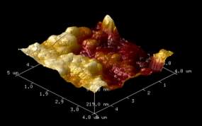
D 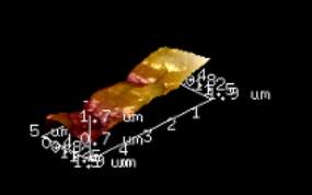
E 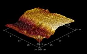
F 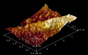
Figure 4.6.1: AFM micrographs of 0.3M FeCl3, 0.3M NiSO4.6H2O, 0.3M CoSO4.7H2O co-deposits obtained from ethaline on a copper substrate at various times: (A) 30 mins, (B) 30 mins showing edge, (C) 60 mins, (D) 90 mins, (E) 120 mins, (F) 150 mins.
4.6.2. Energy-dispersive X-ray spectroscopy (EDXS)
Table 4.6.2: A table showing metal composition of the deposits
| Plate Composition | Time/ min | % mass | ||
| Iron | Cobalt | Nickel | ||
| FeCl3+ CoSO4.7H2O+
NiSO4.6H2O |
30 | 73.52 | 17.72 | 8.78 |
| FeCl3+ CoSO4.7H2O+
NiSO4.6H2O |
60 | 55.83 | 20.33 | 23.84 |
| FeCl3+ CoSO4.7H2O+
NiSO4.6H2O |
90 | 72.23 | 16.52 | 11.24 |
| FeCl3+ CoSO4.7H2O+
NiSO4.6H2O |
120 | 72.79 | 16.5 | 10.71 |
| FeCl3+ CoSO4.7H2O+
NiSO4.6H2O (VCl3) |
60 | 61.52 | 15.38 | 23.11 |
From the Energy Dispersive X- ray Spectroscopy data it is easy to see the trends, the general composition did not change. The table above shows that for 30, 90, and 120 minutes the composition was relatively unchanged at ~73% Fe, ~17% Co and ~10% Ni. This was to be expected from this method of electroplating. Methods described in the literature review [50, 51] plated Ni on to the substrate first and then allowed Co or Fe to be adsorbed after replacing Ni in the lattice. If this method had been perused a much different % composition would have occurred with less than 50% being Fe and Co. Nickel could have also been in a low % composition due to some reports of Ni deposition being inhibited when adsorption starts to happen on the deposit. [51]
Since no Vanadium appeared in the EDXS, it can be assumed that it didn’t plate onto the substrate. However, there was a much higher Ni content on the two 60 min plates.
B 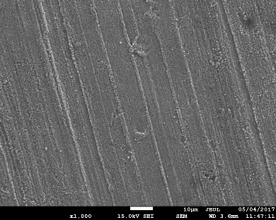
A 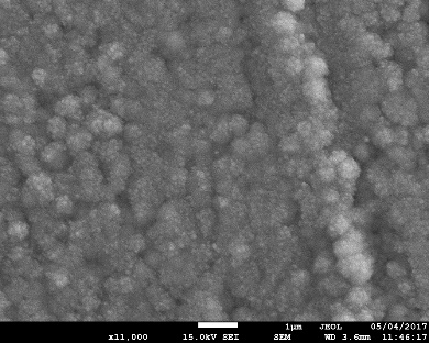
D 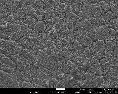
C 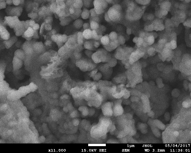
F 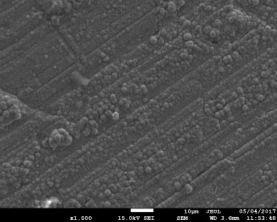
E 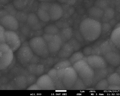
H 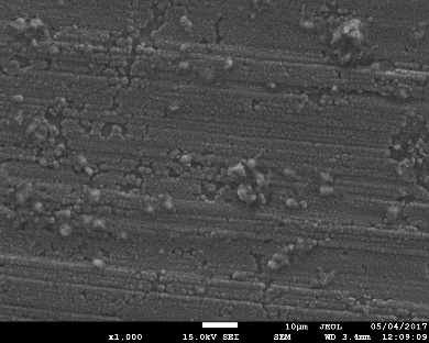
G 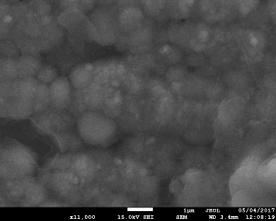
Figure 4.6.2: SEM micrographs of FeCl3, NiSO4.6H2O, CoSO4.7H2O co-deposits obtained from ethaline on a copper substrate at various times: (A) 30 mins x1000, (B) 30 mins x11000, (C) 60 mins x1000, (D) 60 mins x11000, (E) 90 mins x1000, (F) 90 mins x11000, (G) 120 mins x1000, (H) 120 mins x11000.
From the SEM, the deposits have no visible cracks at 11000x. The lines from the copper are visible due to the deposit being thin at the shorted plating times but you can see the deposits increasing in thickness.
These micrographs are similar those shown in the paper by Poznyak et al. [4] as well as those described in the paper by Lallemand et al. [56] The deposit is homogeneous where no aggregate can be distinguished at least at the magnification range used. The longer the plating went on for the larger the cluster that formed, which is to be expected.
4.7. Cyclic Voltammetry
See appendix for Figures
Table 4.7.1.: Cyclic Voltammetry
| Metal Salt | Electrolyte | Additive | Oxidation Peak (Stripping)/ V | Reduction Peak (Plating)/ V |
| N/A | Ethaline | N/A | N/A | N/A |
| N/A | Reline | N/A | N/A | N/A |
| FeCl3 | Ethaline | N/A | 0.44 | 0.24 |
| FeCl2 | Ethaline | N/A | 0.57, -0.28 | 0.32, -1.21 |
| CoCl2 | Ethaline | Saccharin | -0.05 | -0.47 |
| CoCl2 | Reline | Saccharin | 0.18 | -0.4 |
| CoSO4.7H2O | Ethaline | N/A | -0.70 | – |
| CoSO4.7H2O | Ethaline | Saccharin | 0.04 | -0.49 |
| CoSO4.7H2O | Reline | N/A | 0.00 | -0.95 |
| CoSO4.7H2O | Reline | Saccharin | 0.18 | -0.53 |
| NiCl2 | Ethaline | N/A | 0.35 | -0.92 |
| NiCl2.6H2O | Ethaline | N/A | 0.90 | -0.47 |
| NiSO4.6H2O | Ethaline | N/A | 0.30 | -0.71 |
| CoCl2 + FeCl3 + NiCl2 | Ethaline | N/A | 0.47, -0.01 | 0.32, -0.63,
-1.24 |
| CoCl2 + FeCl3 + NiCl2 | Ethaline | Saccharin | 0.45, -0.02 | 0.33, -0.64,
-1.25 |
| CoCl2 + FeCl3 + NiCl2 | Reline | N/A | 0.24 | -0.50 |
| CoCl2 + FeCl3 + NiCl2 | Reline | Saccharin | 0.26 | -0.49 |
The cyclic voltammetric technique was used to get general behavior of the deposition process. A study of deposition of all three metals was carried out; Fe, Co and Ni in various salt forms. This was used to identify the reference behavior that could later be compared to a CV run of all three metals in both DES solutions.
First black sample of Ethaline and reline were run to check for any impurities- as you can see in Figure 4.7.1. and Figure 4.7.2. respectively.
Then to compare the effects of the DES on the CV CoCl2 was used with Saccharin. Co was chosen instead of Iron due to it producing a much tidier set of results with only one clear deposition and stripping peak- Figure 4.7.5 and Figure 4.7.6. Changing the Des from ethaline to reline shifted the peaks to the right with the oxidation peak going from -0.05V to 0.18V.
CoSO4.7H2O in ethaline was then used with and without an additive so compare the effects. Without the additive as shown in Figure 4.7.7. there are no distinguishable peaks. However, with saccharin as an additive in Figure 4.7.8. there are distinguishable peaks at 0.04V and -0.49V. The same is true for the effects of CoSO4.7H2O in reline as shown in Figure 4.7.9 and Figure 4.7.10.
When the CV of all three metals was run in ethaline only distinguishing peaks from Fe- 0.47V and 0.32V- and Ni- -0.01V and -0.64V- appeared. However, the deposition peak for Co was present -1.24V but no stripping peak. (Figure 4.7.13.) From previous work by Vijayakumar et al. it was found that the Ni and Co peak can overlap and the Ni peak is generally larger in size. That is why the stripping Co peak could not be seen. When saccharin was added to the solution the peaks all shifted slightly to the left but the shape of the Voltagram remained the same (Figure 4.7.14).
When all three meatal were run in reline however the only metal that showed any peaks was Co. when saccharin was added these peaks shifted slightly also (Figure 7.7.14 and Figure 4.7.15.).
5. Conclusion
The electrodeposition of iron onto different substrates- copper and brass- from different DES media- ethaline and reline- was achieved. However, the initially the quality of the plates was lacking due to oxidation of the iron that had been plated. The metal salts were varied to try to eliminate some problems that were occurring: when Fe was just being electroplated from FeCl3, the deposit would rust in a short space of time, so the metal salt was changed to FeCl2. This didn’t plate as well as FeCl3 and still rusted, FeCl2.4H2O was also the same.
This meant that other metals needed to be deposited in coordination with Iron. As there was a lot of source material around it was decided that nickel and cobalt would make suitable co-deposits as they are in the iron group- elements that are somewhat related to iron.
The substrate that was chosen was readily available to use and was relatively inexpensive. The metal was deposited successfully onto both the copper and the brass. However, copper was selected as it fit the handmade cells better than the thinner brass. Unfortunately, the copper used was not completely flat from when it was sheet formed- it contained small pits and troughs. These showed up on the SEM and the AFM images.
When it came to changing the voltage, if the voltage was to low deposition didn’t occur and if it was too high then the deposits would bubble and there would be lots of pits. The deposits also came out black instead of grey and didn’t have an even coverage over the entire substrate.
Additives were introduced to the DES to try and reduce stress in the deposits. This was successful as the deposits were much better with saccharin, this has been attributed to the sulphonamide group. The brightening effect of saccharin was attributed to this severe drop in roughness.
This research could be taken in many directions such as investigation the adsorption of Fe and Co into a Ni lattice. This could be done by first plating Ni onto a substrate then plating the other metals on to it separately.
Another direction in which this work could be taken is investigating when the additive saccharin is the best brightener to use. This work has already started to be investigated, but the moment they are still theories with only conclusive evidence to support it.
Areas upon which improvement could have been made; higher temperatures could have been used up to and exceeding 100OC- this would help with reline as it is far denser than ethaline and the mass transport would be much slower. Thus, meaning longer deposition times compared to the less dense ethaline where mass transport can occur faster.
Future work could be concentrated on the use of reline as a media. Work would have to be done first on finding the right concentration of metal salts to use so the reline can dissolve it all. Increasing temperature could also help as this would reduce the density and improve mass transport to the cathode. Since all the literature used reline as its primary DES in electroplating, there is far more literature available for reline than for any other DES, it would make sense for the next step to be in that direction.
Further work could also be carried out on the substrate- since electrodeposition of Ni-Fe-Co films have magnetic properties and are used in computer read/ write heads [23] a method of electroplating onto a substrate small enough to replace those electrodeposited from sulphate and chloride baths.
References
[1] W. Simka, D. Puszczyk and G. Nawrat, Electrochim. Acta, 2009, 54(23), pp. 5307-5319.
[2] W. A. Macfadyen, Trans. Faraday Soc.,1920, 15, pp. 126- 198
[3] A. K. Thakur, V. Srinivas, T. Sahoo. and A. C. Mishra, J. Appl. Phys., 2011, 109(7), p. 73901.
[4] S. K. Poznyak, V. V. Kharton, J.R. Frade and M. G. S. Ferreira, Mater. Sci. Forum, 2006, 514-516, pp. 88-92.
[5] E. L. Smith, A. P. Abbott and K. S. Ryder. Chem. Rev., 2014,114(21), pp. 11060- 11082.
[6] W. Ogihara, N. Suzuki, N. Nakamura and H. Ohno, Polym. J., 2006, 38(2), 117-121.
[7] J. S. Wilkes & M. J. Zaworotko, Chem. Comms., 1992, 1992(13), 965.
[8] P. Bonhôte, A. -P. Dias, N. Papageorgiou, K. Kalyanasundaram and M. Grätzel, Inorg. Chem., 1996, 35(5), 1168-1178.
[9] A. B. McEwen, H. L. Ngo, K. LeCompte and J. L. Goldman, J. Electrochem. Soc., 1999, 146(5), 1687.
[10] D. R. MacFarlane, P. Meakin, J. Sun, N. Amini and M. Forsyth, J. Phys. Chem. B, 1999, 103(20), 4164-4170.
[11] R. B. Leron, A. N. Soriano and M, -H, Li, J. Taiwan Inst. Chem. Eng., 2012, 43(4), 5561-557.
[12] A. P. Abbott, G. Capper, D. L. Davies, R. K. Rasheed and V. Tambyrajah, Chem. Comms., 2002, 1, 70- 71.
[13] R. B. Leron and M, -H, Li, Thermochim. Acta, 2012, 546, 54- 60.
[14] J. S. Wilkes, J. A. Levisky, R. A. Wilson and C. L. Hussey, Inorg. Chem., 1982, 21(3), 1263-1264.
[15] Q. Zhang, K. De Oliveira Vigier, S. Royer & F. Jérôme, Chem. Soc. Rev., 2012. 41(21), 7108.
[16] K. S. Ryder, K. J. McKenzie and A. P. Abbott, ACS Symp. Ser., 2007 pp. 186-197.
[17] F. Rasmussen, J. Ravnkilde,P. Tang, O. Hansen and S. Bouwstra, (2001). Sens. Actuators A, 2001, 92(1-3), 242-248.
[18] M. Li, Z. Wang and R. G. Reddy, Electrochim. Acta, 2014, 123, 325- 331.
[19] I, Z, Rahman, M. V. Khaddem-Mousavi, A. A. Gandhi, T. F. Lynch and M. A. Rahman, J. Phys.: Conf. Ser., 2007, 61, 523-528
[20] T. Yanai, K. Shiraishi, T. Akiyoshi, K. Azuma, Y. Watanabe, T. Ohgai, T. Morimura, N. Masaki, H. Fukunaga, AIP Adv., 2016, 6(5), 055917.
[21] L. Altamirano-Garcia, J. Vazquez-Arenas, M. Pritzker, R. Luna-Sánchez and R. Cabrera-Sierra, J. Solid State Electrochem., 2014, 19(2), 423-433.
[22] S. Deng, & Z. Gong, Anti-Corros. Methods Mats., 2003, 50(4), 267- 270.
[23] D. Kim, D. -Y. Park, B. Yoo, P. Sumodjo and N. Myung, Electrochim. Acta, 2003, 48(7), 819-830.
[24] K. Nakamura, M. Umetani and T. Hayashi, Surf. Technol., 1985, 25(2), 111-119.
[25] H. E. Cleaves and J. G. Thompson, The metal-iron. McGraw-Hill Book, New York, 1935.
[26] Harr, R. E., 1955. Electroplating of iron. USA, US Pat. US 2710832 A.
[27] M. Izaki, Mod. Electroplat., 2011, 309-326.
[28] Fisher, F., 1911. Process for the manufacture of ductile electrolytic iron.. USA, US Pat. US 992951 A.
[29] C. T. Thomas and W. Blum, J. Electrochem. Soc., 1930, 57(1), pp. 59-77.
[30] C. F. Lowrie, Met. Finish., 2002, 100, 253-256.
[31] C. Kasper, J. Res. Natl. Bur. Stand. 1937, 18(5), 535.
[32] P. K. Subramanyan and W. M. King, Plat. Surf. Finish., 1982, 2(69), p. 48.
[33] J. D. Thomas, O. J. Klingenmaier and D. W. Hardesty, Trans. Inst. Met. Finish., 1969, 47, 209.
[34] S. D. Lawes, S. V. Hainsworth, P. Blake, K. S. Ryder and A. P. Abbott, Tribol. Lett., (2009) 37(2), 103-110.
[35] [35] W. B. Stoddard, Jr., Trans. Electrochem. Soc., 1943 ,84, 305
[36] V. P. Revyakin and P. D. Myaniskov, Vestn. Mashostr., 1957, 37(4), 64, Chem. Abstr., 1957, 51, 11887b.
[37] F. Muller, E. Heuer, and O Witnes, Z. Electrochem., 1941, 47, 135.
[38] M. P.Melkovand, B. V. Namakonov, Moskow Motering Inst.,Russian Patent 238,981 (1968); Metal Finish. Abstr.,1969, 11(4),159.
[39] S. Okada, 1950, Japanese Patent 329
[40] K. L. Kossler and R. R. Sloan, Electrotyp. Stereotyp. Mag., 1952, 38 (7), 7
[41] J. Poor (to Van der Horst Corp. of Am.),1956, U.S. Pat. 2,745,800
[42] N. T. Kudryavtsev and M. M. Mel’nikov, Nauchn. Dokl. Vyssh. Shk. Khim. i Khim. Tecknol.,1958, 1, 173; Chem. Abstr., 1959, 53, 913c
[43] M. E. Farmer, D. C. West, and C. D. Darlington, Plating, 1969, 56, 699
[44] Y. Dai, J. Van Spronsen, G. -J. Witkamp, R. Verpoorte, Y. H. Choi, Anal. Chim. Acta, 2013, 766, 61-68
[45] B. Tang, K. H. Row, Monatshefte für Chemie – Chemical Monthly, 2013,144 (10), 1427-1454
[46] M. Figueiredo, C. Gomes, R. Costa, A. Martins, C. M. Pereira, F. Silva, Electrochim. Acta, 2009, 54(9), 2630-2634
[47] R. Böck, S. -E. Wulf, Trans. IMF, 2009, 87(1), 28-32
[48] H.Y. Yang, X. W. Guo, X. B. Chen, S. H. Wang, G. H. Wu, W. J. Ding, N. Birbilis, Electrochim. Acta, 2012, 63, 131- 138
[49] H. Yang, X, Guo, N, Birbilis, G. Wu, W. Ding, Appl. Surf. Sci., 2011, 257(21), 9094-9102
[50] J. Vijayakumar, S. Mohan, S. Anand Kumar, S. R. Suseendiran, S. Pavithra, Int. J. Hydrogen Energy, 2013, 38(25), 10208-10214
[51] E. Gomez, J. Ramirez, E. Valles, J. Appl. Electrochem., 1998, 28, 71-79
[52] H. Li, F. Ebrahimi, Mater. Sci. Eng. A, 2003, 347(1-2), 93-101
[53] M. Donten, H. Cesiulis, Z. Stojek, Electrochim. Acta, 2000, 45(20), 3389- 3396
[54] S. -H. Kim, H.-J. Sohn, Y.-C. Joo, Y.-W. Kim, T.-H. Yim, H.-Y. Lee, T. Kang, Surf. Coat. Technol., 2005, 199(1), 43-48
[55] F. Lallemand, L. Ricq, P. Berçot, J. Pagetti. Unpublished work
[56] F. Lallemand, L. Ricq, E. Deschaseaux, L. De Vettor, P. Berçot, Surf. Coat. Technol., 2005, 197(1), 10- 17
[57] F. Lallemand, L. Ricq, M. Wery, P. Berçot, J. Pagetti. Appl. Surf. Sci., 2004, 228(1- 4), 326-333
[58] J. Zarpellon, H.F. Jurca, J.J. Klein, W.H. Schreiner, N. Mattoso, D.H. Mosca, Electrochim. Acta, 2007, 53(4), 2002- 2008
[59] S. Lambert, Circuit World, 2006, 32(4), 36- 41.
Appendix
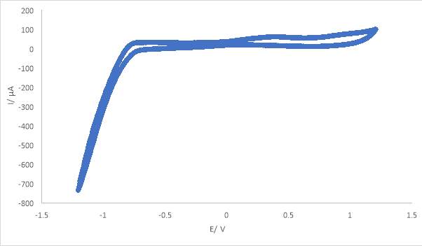
Figure 4.7.1.:CV Ethaline
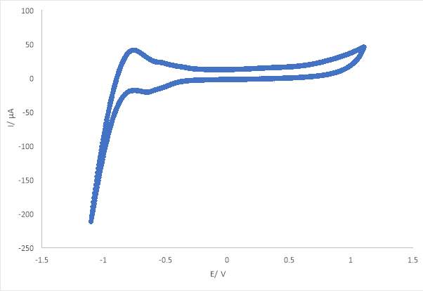
Figure 4.7.2.: CV Reline
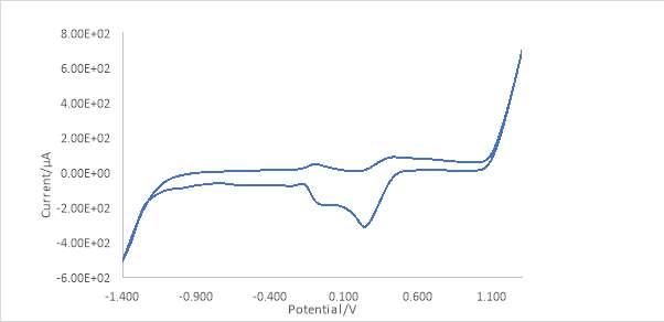
Figure 4.7.3.:CV 0.3M FeCl3 Ethaline
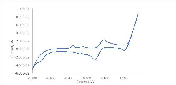
Figure 4.7.4.: CV 0.3M FeCl2 Ethaline
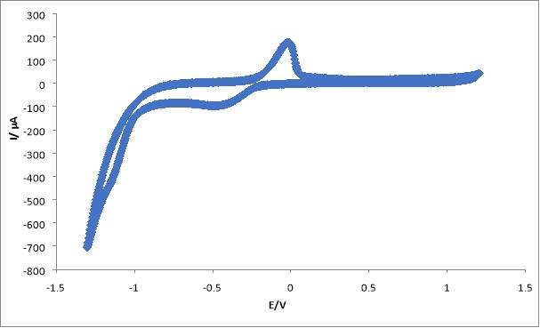
Figure 4.7.5.: CV 0.3M CoCl2 Ethaline Saccharin
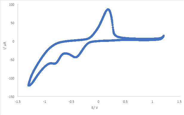
Figure 4.7.6.: CV 0.3M CoCl2 Reline Saccharin
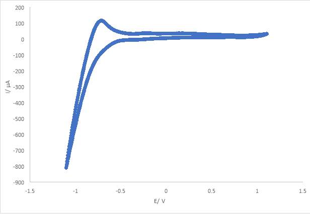
Figure 4.7.7.: CV 0.3M CoSO4.7H2O Ethaline

Figure 4.7.8.: CV 0.3M CoSO4.7H2O Ethaline Saccharin
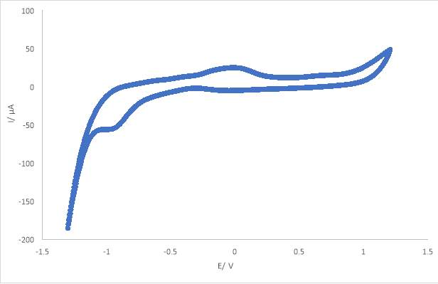
Figure 4.7.9.: CV 0.3M CoSO4.7H2O Reline
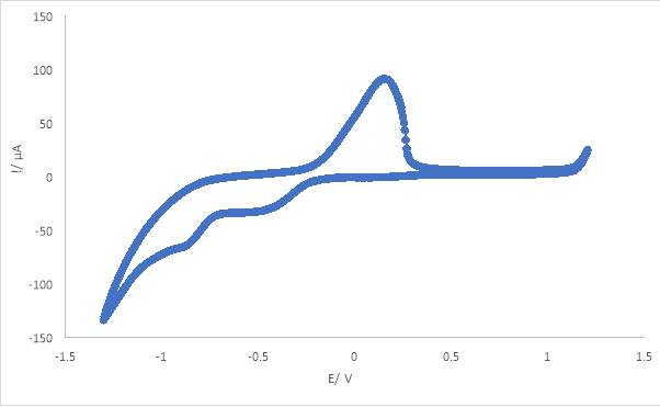
Figure 4.7.10.: CV 0.3M CoSO4.7H2O Reline Saccharin

Figure 4.7.11.: CV 0.3M NiCl2 Ethaline
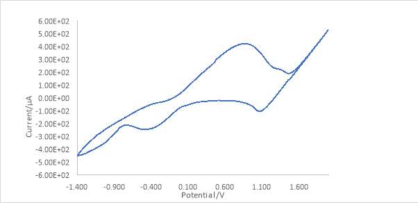
Figure 4.7.12.: CV 0.3M NiCl2.6H20 Ethaline
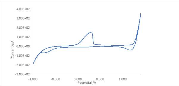
Figure 4.7.12.: CV 0.3M NiSO4.6H2O Ethaline
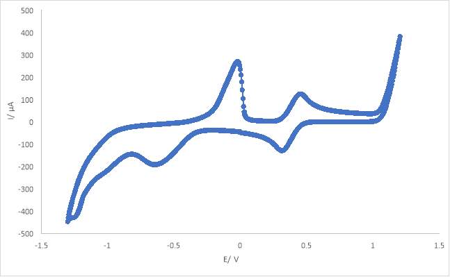
Figure 4.7.13.: 0.3M FeCl3+ 0.3M CoCl3+ 0.3M NiCl2Ethaline
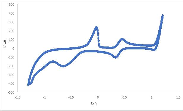
Figure 4.7.14.: 0.3M FeCl3+ 0.3M CoCl3+ 0.3M NiCl2Ethaline Saccharin
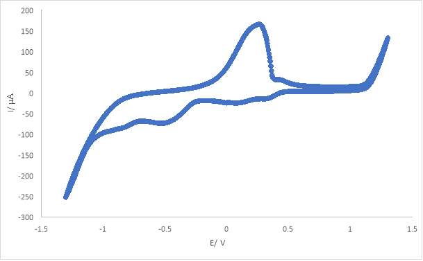
Figure 4.7.15.: 0.3M FeCl3+ 0.3M CoCl3+ 0.3M NiCl2Reline
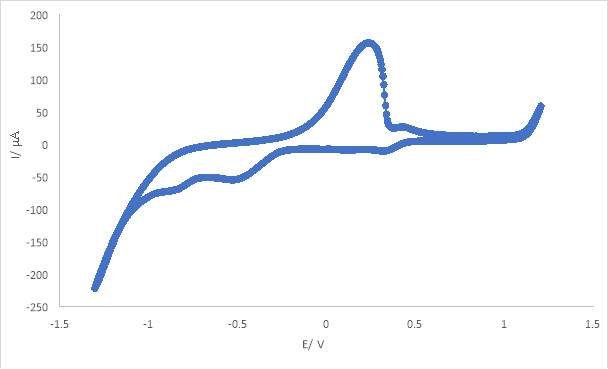
Figure 4.7.16.: 0.3M FeCl3+ 0.3M CoCl3+ 0.3M NiCl2Ethaline Saccharin
Cite This Work
To export a reference to this article please select a referencing stye below:
Related Services
View allRelated Content
All TagsContent relating to: "Chemistry"
Chemistry is a science involving the study of the elements and matter at the atomic and molecular level including their composition, structure, properties, behaviour, and how they react or combine.
Related Articles
DMCA / Removal Request
If you are the original writer of this dissertation and no longer wish to have your work published on the UKDiss.com website then please:


