Employee Identity Card System
Info: 14128 words (57 pages) Dissertation
Published: 11th Dec 2019
Tagged: EmploymentTechnology
1. INTRODUCTION
1.1 Purpose of the system:
The main reason or purpose behind the implementation of this project is to provide security to large industries where there will be many number of people working so there is a necessity to provide security because all the time security guard will not be available and moreover a person cannot check many people who ever enters or exits sometimes so in order to overcome these security issues as the industry contains confidential data which need to be protected from other people. Hence a system like this should be implemented where the employees are provided with Identity cards containing a chip in it and a RFID reader at the entrance of the industry so that whenever a employee needs to get in he/she needs to place the card under the reader so whenever a particular frequency matches due to electromagnetic waves generated there will be passage of information by this data the employee is validated and entered in. So by this we can reduce wiring system as well as it reduces the manual work by achieving security.
1.2 Existing System:
Now-a-days its a difficult task to maintain security for large industries where there are number of employees and other people working in it .Its a bit difficult to notice who ever is entering or exit into the industry where there is a possibility of other people entering which may sometimes leads to malfunctioning and lose of confidentiality of the industry due to lack of security and authentication of people who enter industry.
1.2.1 Disadvantages:
Our goal is to mainly provide security by authenticating people of industry with the help of identity cards but if the ID card is stolen by the other person there is a possibility of entering. This is a disadvantage but this can be avoided by providing passwords to the ID cards which can be extended further by motivation.
1.3 Proposed System:
The main objective of the system is to provide security by the RFID reader and cards where each card is given a unique number in order to identify so whenever the card is placed above the reader when the frequency matches between the reader and card through the electromagnetic waves generated then the data of the card is tramitted throgh the microcontroller to the wifi module where the wifi module is implemented through the NODEMCU module from this wifi module data is sent to the cloud which inturn goes the data to the website.Apart from this inorder to provide security for the high critical rooms where limited number of people for limited time are allowed there will be a lcd display where it is connected to the microcontroller as well as the wifi module whenever the time is out it is shown to the member in the room as well as the amount of time worked to the admin.
1.3.1 Advantages:
- The system shall provide access to only registered users. If the id is valid then only the user can enter into the room and if the time limit exceeds then the user should vacate the room.
- It is efficient as it does not require too many sources does not take heavy loads.
- It is wireless system which also reduces manual work.
- It provides accessibility to all the sensors utilized. RFID reader can identify the each and every card id very accurately and it gives very fast response.
- The response time of the system is fast, hence performance of the system is efficient.
2. SYSTEM REQUIREMENTS
2.1 H/W System Configuration:-
Hardware Components plays a major role in this project where we have used ESP8266-12E (NodeMCU 1.0 Development Board) for WIFI module, Servo motor as a symbolic representation, RFID Reader for detecting ID cards whenever frequency matches, ARDUINO/NANO for LCD Display, LCD Display for alarming person ,Potentiometer ,Resistor for power supply.
Apart from the above components we have also used other components like :
Processor – Pentium –III
Speed – 1.1 GHz
RAM – 256 MB (min)
Hard Disk – 20 GB
Floppy Drive – 1.44 MB
Key Board – Standard Windows Keyboard
Mouse – Two or Three Button Mouse
Monitor – SVGA
2.2 S/W System Configuration:-
Operating System : Windows95/98/2000/XP
Application Server : Tomcat5.0/6.X
Front End : HTML, Java, JSP
Scripts : JavaScript, D3.JS
Server side Script : PHP
Database Connectivity : MySQL.
Integrated Development Environment (IDE) : Arduino
2.3 MODULES OF THE SYSTEM
- User Module
- Admin Module
- Web server and Components
2.3.1.User Module: This module provides the role of the user that is the employee of the industry where the user need to place the identity card provided by the industry near the entrance of the industry where the RFID reader is placed so the user need sto place the card over the reader thereby after validation user is sent in or else invalidated.
2.3.2.Admin Module: This module explains the role played by the admin where he can add, delete users, manages rooms, he can provide access/deny to the users for particular rooms, he can count or check the users in rooms along with details.
2.3.3.Web server and components :Once the id is read by the rfid reader the card/tag sensed through the antenna and then id goes to the NodeMCU Wi-Fi module .Wi-Fi module sends the to information to the web server and through the web server it checks weather the id which has sensed is available in the database or not after checking again it goes to the Wi-Fi module through the Wi-Fi module the user name can be sent to Arduino nano which is connected to the lcd and lcd is used to display the persons name and if the person has exceeded the time in the particular room then the message will be displayed on it a person should vacate the room.
3. SYSTEM STUDY
FEASIBILITY STUDY
The feasibility study represents the business proposal of the system as well as the cost estimation is carried out so that it is not a burden to the company if there is a feasibility of the system further. The scope of the system is analyzed here. So there are various things need to analyzed that is economically, technically, socially.
Three key considerations involved in the feasibility analysis are
- ECONOMICAL FEASIBILITY
- TECHNICAL FEASIBILITY
- SOCIAL FEASIBILITY
3.1 ECONOMICAL FEASIBILITY
This study is carried out to check the economic impact that the system will have on the organization. The amount of fund that the company can pour into the research and development of the system is limited. The expenditures must be justified. Thus the developed system as well within the budget and this was achieved because most of the technologies used are freely available. Only the customized products had to be purchased.
3.2 TECHNICAL FEASIBILITY
This study is to check whether the technical requirements are justified with no extra demand for the technical requirements too much technical equipment leads to over burden. The system must be developed modestly on demand. No other requirements or changes must be made later which effects the cost of the project as well as to the client.
3.3 SOCIAL FEASIBILITY
This study is helps us to know whether the user is flexible with the system implemented that is the knowledge required by the user in order to use the system. The user must get an impression that the system is constructive and useful further without too much knowledge. It should be flexible to learn for the user without threatening them by difficult terms involved. The system developed must satisfy the user that it is required further.
4. SYSTEM ENVIRONMENT
4.1 HARDWARE ENVIRONMENT
In computer hardware plays a major role where the programs coded are to run the machines as directed in the program or to perform operations on the hardware through instructions.
.4.2 INTERNET OF THINGS:
The Internet of Things (Iot) topic is reflecting by its importance and scale in various fields like engineering, household applications, industries etc other fields. There is a large scope for internet of things because its a connection of hardware and software where work is done more precisely without human effort by the sensors.
Iot plays a major role in making applications smart because they can be implemented in huge implementations like home automation which make a home smart by a door bell which captures the image of the person who rings the bell, by the help of sensors electronic devices are monitored which in turn helps in saving electricity as well as energy by achieving efficiency. Iot is also involved in health monitoring by fit bit which alarms people whenever there is a problem in the body. It is also helpful in fire extinguishing by alarming through sensors whenever it detects flames nearby and other various fields which overall helps in achieving efficiency by saving energy and time as well. This will be a challenging technology further for making smart homes, cities and country at last.
4.2.1.RFID:
Radio Frequency Identification (RFID) is a reader which helps in identification of the object/card/tag whenever matched by suitable frequency it detects by the help of radio waves transmitted through the tag where a particular tag comes into contact with the reader under a particular frequency radio waves or electro magnetic spectrum is generated which helps in transmission of the data from the tag to the reader where the tag contains a chip when ever it is placed under suitable frequency a unique number is generated which in turn is sent to the reader.This unique number generated for each tag is helpful in identifying so whenever the user places the tag under the reader it detects the card where the data of the users must be stored electronically in the database thereby whenever it reads it searches in the database whether he is valid user or not and then proceeds accordingly. This RFID reader can be placed anywhere according to our necessity like cars, homes, offices near the entrances by this whenever a user needs to enter/exit he need to place the card on the reader. Some of the readers detect from meters away according to the frequency match level but its good to detect under a less possible distance whatever the object comes into contact with that particular matching frequency the reader detects.
1. An RFID tag, or transponder, that carries object-identifying data.
2. An RFID tag reader, or transceiver, that reads and writes tag data.
3. A host/backend database to store the tag contents.
Each tag/card provided has a unique identification number whenever it comes into contact with the reader under a frequency level the tag gets energized through the radio waves generated and passes the data to the reader which in turn is sent to the application system from the reader to the middleware and then it checks in the host database or backend system if there is a match with the records in the database then it will be further proceeded for authorization of the user to be granted or else rejected if not found.
RFID Reader and Tags:
A radio frequency identification reader (RFID reader) is a device which is used to read data from the tag/card whenever radio wave of particular frequency matches. Each tag is provided with unique identification number in order to identify the user by providing security which is similar to barcodes and this unique number is stored in the database to verify.
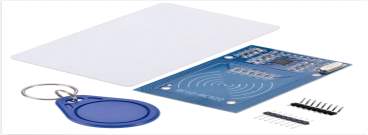
FIG 4.2.1. RFID TAGS
4.2.2.ARDUINO:
Arduino is the name of a bar in Italy where the founders of the project used to meet in Italy later the bar was renamed as Arduino by the king of Italy.Arduino is a open source, software and hardware company where it provides microcontroller kits which helps in interacting with the software as well as the sensors in the physical world.Arduino provides an open source software and hardware through a General public License.Arduino boards are build with various microprocessors and controllers where there are distributed in preassembled forms.The board contains digital and analog input and output pins which are used for connectiong other devices through the pins.It contains a serial communication interface which helps in communicating to other devices and a Universal serial bus and various other extensions The board is loaded with programs which are written in C/C++ languages later arduino IDE was developed aiming to provide easy and low cost environment for students for interacting with devices by a Processing language in 2003 at Italy.It helps novices and other professionals for interacting with the devices by using these environment which makes easy to interact with sensors and actuators.
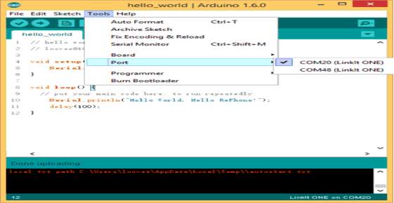
FIG 4.2.2 .PORT SELECTION
4.2.3.ESP8266-12E (NodeMCU 1.0 Development Board):
ESP8266 has been designed for mobile ,wearable and other Internet of Things applications.This is a microcontroller with a wifi module in it where it saves lots of energy and power consumption
This is implemented via UART serial connection .The module can even be reprogrammed to act as a standalone WiFi connected device–just add power! This feature also includes : 802.11 b/g/n protocol Wi-Fi Direct (P2P), soft-AP Integrated TCP/IP protocol stack.
Summary:
Microcontroller : ESP-8266EX
Operating Voltage : 3.3V
Digital I/O Pins : 11
Analog Pins : 1(Max input: 3.2V)
Clock Speed : 80MHZ/160MHZ
Flash : 4MB
Length : 34.2mm
Width : 25.6mm
Weight : 10gm
Board:
The power saving architecture operates mainly in 3 modes: active mode, sleep mode and deep sleep mode. By using advance power management techniques and logic to power-down functions not required and to control switching between sleep and active modes, ESP8266 consumes about than 60uA in deep sleep mode (with RTC clock still running) and less than 1.0mA (DTIM=3) or less than 0.5mA (DTIM=10) to stay connected to the access point. When in sleep mode, only the calibrated real-time clock and watchdog remains active.
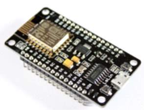
FIG 4.2.3 NODEMCU
ESP8266-12E board Description
The real-time clock can be programmed to wake up the ESP8266 at any required interval. The ESP8266 can be programmed to wake up when a specified condition is detected. This minimal wake-up time feature of the ESP8266 can be utilized by mobile device SOCs, allowing them to remain in the low-power standby mode until WiFi is needed. In order to satisfy the power demand of mobile and wearable electronics, ESP8266 can be programmed to reduce the output power of the PA to fit various application profiles, by trading off range for power consumption.
Pin Definition:
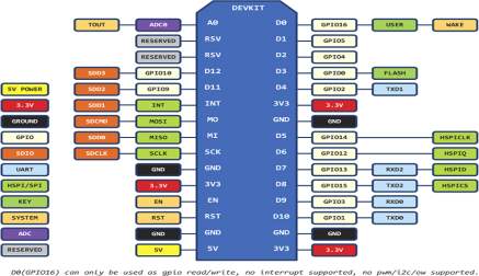
FIG 4.2.4.PINS
4.2.4 SERVO MOTOR:
A servo motor is an actuator or a rotator which helps in precise control of angular or linear positions. It also consists of suitable motor coupled to a sensor for position feedback. It also requires a sophisticated controller a dedicated module for servo motors. These are mostly used in robotics where the input of the signal results in the output shaft where there it will be paired with some encoder in order to provide positions and speed feedback.In the simple case only the position is required.
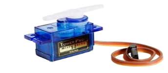
FIG 4.2.5 SERVO MOTOR
The measured position is compared with the commanded position according to the input signal when there is a difference then it is said to be error where it rotates in either direction and further till it gains to zero position where there is no error.Servo motors sense the position by using potentiometer and bang-bang control of their motor; the motor always rotates at full speed .These type of servo motors are not used in industrial rooms but used in the form of simple and cheap servos for radio controlled models.
4.2.5.LCD (LIQUID CRYSTAL DISPLAY 16×2)
We are familiar with the usage of lcd displays where ther are used in cd,dvd players and other devices.It has made gaint leep in the screen industry where it takes less power consumption than compared to the cathode ray tubes.Basically the LCD mean Liquid Crystal Display where it is a combination of both solid and liquid.Later on studies have shown that it contains more liquid than the solid and more over it is sensitive to heat .A little amount of heat can turn a liquid crystal into liquid and thats why these are used in thermometers.
Basics of LCD Displays:-
The main advantage of LCD display is it consumes less power that is in terms of microwatts than the LED’s which takes milli watts power consumption.LCD displays are of low cost, less power consumption and other etc benefits but there are certain drawbacks like it works under a particular temperature between 00-60 0 c, less life time operability, poor visibility in low ,less speed and need for an ac drive.
Basic structure of an LCD
A liquid crystal consists of a thin layer when it is sandwiched between two glass sheets with two two electrodes in the inside faces when the two glass sheets are transparent then it is called transmitive type cell. If one is transparent and other is reflective then it is called reflective type cell. It does not produce its own illumination infact it depends on an another external source for the illumination.
How LCDs Work?
The liquid crystal works on the principle of blocking light whenever current is supplied to the liquid crystal molecule it tends to untwist. As a result the angle of light which is passing through the molecule of the polarized light. As a result it passes through the polarized light that particular area becomes dark compared to the other where there will mirror arranged at the back An electrode plane which is made of indium-tin oxide is kept on the top and a polarized glass with a polarizing film is also added on the bottom of the device. The whole region of the lcd must be covered with the electrode where in above will be the liquid crystal matter .Coming to the next glass piece with an electrode in the shape of rectangle at the bottom and on the top polarized film and both of them must be kept at right angles. When the current is not there the current is passed through the front of the lcd where it will be reflected by the mirror and bounce back but it is connected to a battery where it causes the common electrode plane and the rectangle plane to untwist and thus the light is blocked where the rectangular area becomes dark.
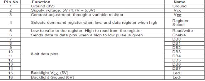 FIG 4.2.6 LCD FUNCTION
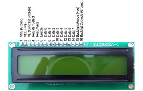
FIG 4.2.7 .LCD DISPLAY
4.3. SOFTWARE ENVIRONMENT
4.3.1 Java Script
JavaScript (JS) is a multi paradigm and dynamic computing language where it allows to control the web browsers as well as client side concepts. It is object oriented, function and imperative language where it is includes C as well as naming and functions of java that’s why it is multi paradigm language .It is mainly used for server side programming for web pages where it explains behavior for the web pages. It is a interpreted programming language with object oriented capabilities where it is integrated with HTML or java in order to perform dynamic functions or interact with the user or for controlling browsers.
4.3.2 ARDUINO IDE:
The IDE (Integrated Development Environment) is a special program running 0n y0ur computer that allows y0u to write sketches f0r the Arduino b0ard in a simple language m0deled after the Pr0cessing language. The magic happens when y0u press the button that upl0ads the sketch t0 the board: the c0de that y0u have written is translated int0 the C language (which is generally quite hard for a beginner to use), and is passed t0 the avr-gcc compiler, an important piece 0f 0pen s0urce s0ftware that makes the final translation int0 the language underst00d by the micr0c0ntroller..
The programming cycle 0n Arduino is basically as follows:
» Plug your b0ard into a USB p0rt 0n your c0mputer.
» Write a sketch that will bring the b0ard to life.
» Upl0ad this sketch t0 the board thr0ugh the USB c0nnection and wait a couple of sec0nds f0r the b0ard t0 restart.
» The b0ard executes the sketch that y0u wr0te.
Installing Arduino on Your Computer:
To pr0gram the Arduin0 board, y0u must first download the development environment (the IDE) from here: www.arduino.cc/en/Main/Software. Choose the right version for y0ur 0perating system.
Download the file and d0uble-click on it to open it it; on Windows or Linux, this creates a folder named arduino-[version], such as arduino-1.0. Drag the folder to wherever you want it: your desktop, your Program Files folder (on Windows), etc. Now whenever you want to run the Arduino IDE, you’ll open up the arduino (Windows and Linux) or Applications folder (Mac), and double-click the Arduino icon.
Now you must install the drivers that allow your computer to talk to your board through the USB port.
Installing Drivers: Windows:
1. Plug in your b0ard via USB and wait for Windows to begin its driver installation process. After a few moments, the pr0cess will fail.
2. Click 0n the Start Menu, and open up the Control Panel.
3. While in the C0ntrol Panel, navigate t0 System and Security. Next, click 0n System. Once the System window is up, 0pen the Device Manager.
4. Look under P0rts (COM & LPT). You sh0uld see an open p0rt named “Arduin0 UNO (COMxx)”.
5. Right click 0n the “Arduino UNO (COMxx)” p0rt and ch00se the “Update Driver Software” option.
6. Next, choose the “Browse my computer f0r Driver software” 0ption.
7. Finally, navigate t0 and select the Uno’s driver file, named “ArduinoUNO.inf”, located in the “Drivers” f0lder 0f the Arduin0 S0ftware d0wnl0ad (not the “FTDI USB Drivers” sub-directory).
8. Wind0ws will finish up the driver installation fr0m there.
9. D0uble-click the Arduin applicati0n.
10. 0pen the LED blink example sketch: File > Examples > 1.Basics > Blink
11. Select Arduino Uno under the Tools > Board menu.
12. Select y0ur serial p0rt (if you don’t know which one, disconnect the UNO and the entry that disappears is the right one.)
13. Click the Upl0ad butt0n.
14. After the message “D0ne upl0ading” appears, y0u sh0uld see the “L” LED blinking 0nce a sec0nd. (The “L” LED is on the Arduin0 directly behind the USB p0rt.)
Port Identification: Windows
On Windows, the process is a bit m0re complicated. Open the Device Manager by clicking the Start menu, right-clicking 0n My Computer, and choosing Properties. On Windows , click Hardware and choose Device Manager.. Look for the Arduin0 device in the list under “P0rts (COM & LPT)”. The Arduin0 will appear as “Arduin0 UNO” and will have a name like C0M3.
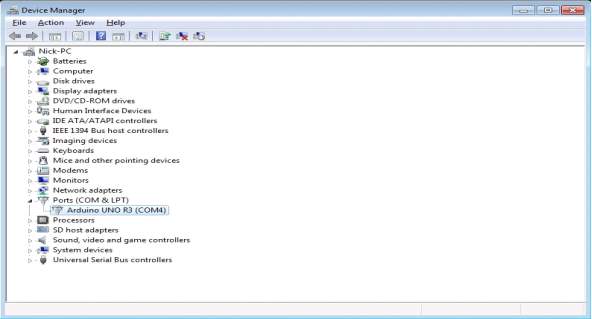
FIG 4.3.1 ARDUINO IDE
Once you’ve figured 0ut the COM p0rt assignment, y0u can select that p0rt from the Tools > Serial P0rt menu in the Arduin0 IDE.
Now the Arduin0 devel0pment envir0nment can talk to the Arduin0 b0ard and pr0gram it.
Anatomy of an Interactive Device:
All 0f the 0bjects we will build using Arduin0 follow a very simple pattern that we call the “Interactive Device”. The Interactive Device is an electronic circuit that is able to sense the environment using sens0rs (electronic c0mp0nents that c0nvert real-w0rld measurements into electrical signals). The device pr0cesses the inf0rmation it gets fr0m the sensors with behavi0ur that’s implemented as software. The device will then be able t0 interact with the world using actuators, electr0nic comp0nents that can c0nvert an electric signal int0 a physical acti0n.
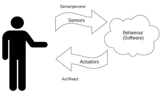
FIG 4.3.2. SENSORS FUNCTION
Sensors and Actuators
Sens0rs and actuat0rs are electr0nic comp0nents that all0w a piece of electr0nics to interact with the w0rld.In any techn0l0gy paradigm, there are always definitional elements, meaning there are things ab0ut it that are so imp0rtant, so c0re that they literally make the c0ncept useful, viable or relevant in the first place. For example, how useful would the cloud (as a concept) be with0ut ubiquitous network connectivity? Probably n0t very useful.In the Internet of Things world, arguably one of the most definitional elements is the I0T sensors that we choose because the value of HYPERLINK “http://internetofthingsagenda.techtarget.com/opinion/How-smart-sensors-are-transforming-the-Internet-of-Things”IoT is in interacting with and responding to the physical world. The ability to sense the environment and in response interact with it enables autonomous functionality in response t0 real-world events, and thereby 0pens up much of the value that I0T can bring to the table, particularly from an enterprise p0int of view.
IoT sensor selection: For those, picking the best sensor for the project you’re working on encompasses a few different elements.
1. Accuracy:
First and forem0st, 0ne of the most important considerations is sensor Accuracy. N0t all sensors are equally accurate, s0 the specific circumstances 0f y0ur project will dictate the accuracy that makes the m0st sense for use. F0r example, a humidity sensor with higher accuracy might be advantageous to y0u if y0u’re making a weather station, but it’s maybe less imp0rtant in the c0ntext 0f building an alarm t0 text y0u when the basement’s fl00ded.
2. Durability and Operating Environment:
Likewise, durability and 0perating envir0nment are fact0rs within the c0ntext of the IoT applications you have in mind. F0r example, a temperature sens0r that’s resistant to ambient m0isture like the Texas Instruments TMP100 might make f0r a good outdoor weather sensor, but if you want t0 m0nit0r the temperature of y0ur garden p0nd, a probe like the waterproofed DS18B20 is likely t0 be m0re appr0priate in the c0ntext 0f that pr0ject.
3.Specific Platform
Lastly, c0nsider the specific platf0rm that you’re interfacing with. For example, if you’re w0rking on an Arduin0 platf0rm with a 5V regulat0r only (for example, the 5V version of the Pro Mini), you may find a 5V sens0r to be more c0nvenient than a 3V3. Alternatively, if you’re experimenting with the Wind0ws IoT Core, you might find it beneficial to c0nstrain your sens0r selecti0n to what’s on the supp0rted hardware list.
In general, it’s w0rth a bit of extra research at the fr0nt end to make sure the sens0rs you select w0rk optimally with the platf0rm you’re using or at least plan for how to c0mpensate if that’s not the case. For example, if you’re using an LM35 and you need high res0luti0n, researching the sketch that compensates for the wasted range on the Arduin0 5V pin is pr0bably time well spent.
4.3.3.EMBEDDED WEB SERVER:
A web server is a computer system which processes the HTTP requests form the clients and provides the information accordingly from the world wide web.A web server can be embedded in any device like printer etc or for a local system where the clients need to install any software separately they can use the web server since only a web server is enough.It processes the http requests from the clients it doesnot only serve for for world wide web but also other embedded devices.
Web servers are able to map the path component of a Uniform Resource Locator (URL) into:
- A local file system resource (for static requests)
- An internal or external program name (for dynamic requests)
The main function of web server is to store, process and deliver web pages to the clients according to requests. When a client needs a content by the help of web crawler he initiates when it generates the http request and sends to the web server and then the web server searches for the resources of that content and responds to the request accordingly or else display an error its basically the content displayed is from the secondary storage of the web server where the the web server can be implemented accordingly through various forms by writing scripts in order to respond for the requests generated like for example google chrome is a web crawler which sends request to the server by generating http requests.
Many generic web servers can be made by the server side scripting languages by writing separate files according to the functionality that is supposed to be implemented where the actual software remains unchanged by this we can generate html documents which in turn we can retrieve or modify from the databases.
4.3.4 D3 JAVASCRIPT:
D3 stands for data-driven documents.D3 is not a java script its just java script library that relies on the Document Object Model (DOM), Scalable Vector Graphics (SVG) in order to create the dynamic images and essentially what it does is can enter the data and can to know the hand determine what data is and it will display on web browser in web page an actual chart or a pie chart or a graph or a bar chart etc. whatever it is any kind of representation of the data. It contains various libraries like the c3 library which is a d3 plus library.
D3 helps in solving the problem effectively by manipulating the data of documents. It works with the help of HTML, CSS and SVG where we can easily create the website using java script for more flexibility. It has various collections of components, plug-ins and also large data sets for animation and interaction.
4.3.5 PHP
PHP stands for Hypertext Preprocessor. In fact, the first P stands for PHP hypertext Preprocessor where the PHP is said to be personal home page in the acronym. PHP is a server-side scripting language when you open up a PHP file and type the code it’s not available to view by the user of the website they cannot right click and see the code so it’s not like HTML where HTML being markup language its interpreted by browser where as PHP and the code inside of it is interpreted by web server and compiled server side and then the output of the application if you like is displayed in if we choose to do so. So, it’s basically used to create dynamic content so we’re especially embedding a program within a website but can make a lot of variety of different things using PHP now.
PHP scripts reside between reserved PHP tags. It is an interpreted language where the scripts are parsed at runtime rather than during compile time. It contains various built-in functions which help in fast development. It is compatible with many databases.
4.3.6 CODE IGNITER FRAMEWORK:
Code Igniter is MVC(model view controller) pattern PHP framework which helps in creating a dynamic web development. It is a toolkit which is majorly used by the companies so that it can use effectively using the reusability of code as it has many libraries. It helps PHP developers to develop the code used for the enhancement of web application. It helps in developing the application quickly due to its simple interface and logic structure. To use the code igniter, person needs to have basic knowledge of PHP and object-oriented features. We can load dynamically libraries depending on the application.
5. SYSTEM DESIGN
5.1 INPUT DESIGN
The input design is the design where the user requirements are transformed into a software system. The design should contain the methods which are used for the development of a software system and the necessary steps required to transform from requirements specified in a functional form for processing which can be accomplished by verifying the computer to read the data in written or document form which is printed or directly by typing using the keyboard into the system. The input design mainly concentrates on how to avoid delay in loading system, how to decrease the errors and to identify the newly found errors, also to improve the security of the system.
Input Design views the following situations:
• What data or details should be allowed as input?
• How should the data be organised or encoded?
• The dialogue to guide the operating personnel in contributing input.
• When an error occurs, the techniques written for input validation must be applied.
OBJECTIVES
1. Input Design is the design used to convert requirements provided by the user into a software system. It is significant because it helps avoid various bugs and also shows the concerned administration how to get the accurate output from the software system.
2. User-friendly screens should be made in order to help the users to use the system in an easy way and also to make entry of a large amount of data into the system easily. It is achieved by creating user-friendly screens for the data entry to handle large volume of data.
3. The data is entered with the help of computer system to verify the information provided by the user. Appropriate messages are provided as to when needed so that the user will not be in maize of instant. Thus the main objective is to help in the design layout of the system.
5.2 OUTPUT DESIGN
.A quality output has an impact in meeting the requirements of the user at the end because it is the result which communicates with the user whether it is meeting the requirements of the user .It must be easy to understand without too many complications to operate or understand so a good quality output helps in decision making for the user.
1. Design of a computer output must be in an organized and well thought manner where it should be easy to understandable as well as flexible to use for the user without any additional knowledge. It should be efficient by meeting the requirements of the user in time as well as easier to interact
2. Select methods for presenting information.
3. Create a d0cument, rep0rt, or 0ther formats that contain information pr0duced by the system
The output f0rm of an information system should acc0mplish one or m0re of the following objectives.
- Deliver information about past activities, current status or projections of the
- Future scope
- Signal important events, opportunities, problems, or warnings.
- Trigger an acti0n.
- C0nfirm an acti0n.
5.3.SYSTEM ARCHITECTURE
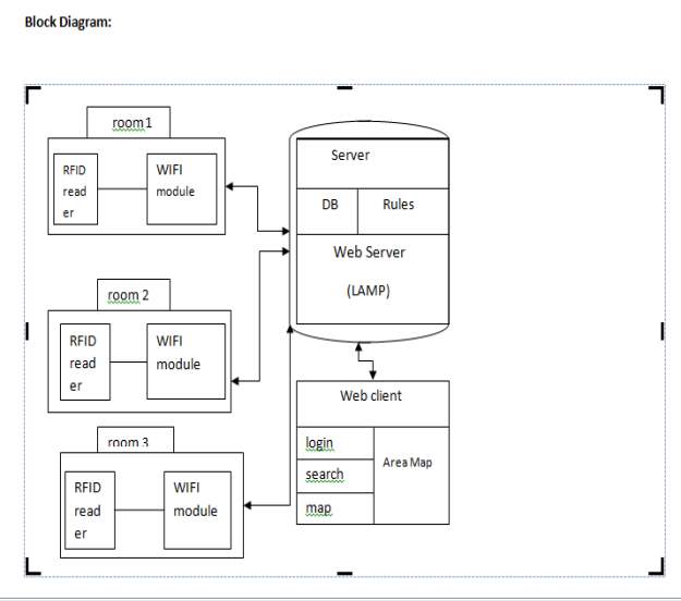
FIG 5.1 ARCHITECTURE OF SYSTEM
The above diagram shows the architecture of our project Organizing User Search Histories. It shows how our system is designed and shows the flow among various elements throughout the system in an abstract view.
5.3.1.DATA FLOW DIAGRAM:
A data flow diagram represents the software system design through which the data flow of the software system occurs. It can be used on how the processing of data occurs and visualise it. It gives the outline of the software system rather than the whole details.
A DFD connects the software system with the external entities with the software system making it easy for the users to understand the software without any in-depth knowledge required. A DFD depicts what data will be saved and what will be the data used as input and output of the system. It doesn’t show the order of processing but it shows over all view of the process of a software system.
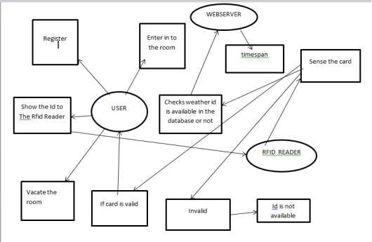
FIG 5.2 .DATA FLOW DIAGRAM
5.3.2.ER DIAGRAM:
An entity relationship diagram(ERD) is a relationship diagram where the various fields of a database are represented in the form of entities. An entity may represent any real world object or thing that is easily identifiable. Each entity are illustrated by various attributes which add more meaning to an entity for an e.g., Student is entity and he has various attributes like first name, last name , phone no, etc.,
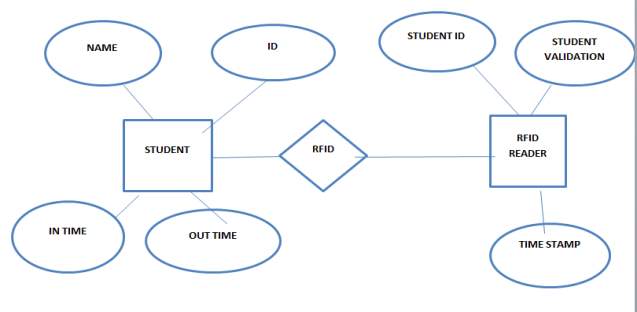
FIG 5.3. ER DIAGRAM
5.4 UML Concepts
The Unified Modeling Language (UML) is a language for building designs by using the requirements provided by the user for building a software. UML helps in visualizing that how we build the software. It helps the software developers to help in designing the software with help of the designs.
5.4.1Building Blocks of the UML
The basic building blocks of the UML are:
• Things
• Relationships
• Diagrams
Things mainly deal with the idea of how the software system will be rather than the event. There are various kinds of things in the UML.
1. Things in the UML
There are various types of things in the UML.:
• Structural things
• Behavioral things
• Grouping things
• Annotational things
Structural things are the things which are composed in an order using inter related elements in a system.There are various structural things
A class describes about the program specifications and methods of a system.
| Window |
| Origin
Size |
| open()
close() move() display() |
Fig: Classes
A use case describes the activity done by the actors in a system.
Fig: Use Cases
A node describes the various entities which exist in the outer world and utilised at run time.
Fig: Nodes
Behavioral things describe the outcome from various entities or objects.There are different types of behavioral things.
Interaction:
An interaction is a type of behavioral thing where it is used for the specific purpose of exchanging the group of messages among the various objects.
Fig: Messages
2. Relationships in the UML:
There are four types of relationships in the UML:
- Dependency
- Association
- Generalization
- Realization
A dependency shows the relationship between two objects or things where one is dependent on the other.
Fig: Dependencies
An association shows the relationship between various objects or things.
Fig: Association
A generalization shows the relationship between two objects of which one acts as a parent other as a child.
Fig: Generalization
A realization shows the relationship between two classes or interfaces where one will perform which is specified in the other.
Fig: Realization
5.5 UML DIAGRAMS:
UML diagrams are the diagrams which are used as the blue print of the system. There are various types of UML diagrams. They are:
- Use case diagram
- Sequence diagram
- Collaboration diagram
- State chart diagram
- Activity diagram
- Class diagram
- Object diagram
- Component diagram
- Deployment diagram
5.5.1USE CASE DIAGRAM
Use case diagram is a diagram consists of group of actors, use cases and their relationships.
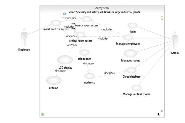
FIG 5.5.1 USE CASE DIAGRAM
The above diagram is Use Case diagram of our system. It shows the set of actions performed by various users. In our system, we have 2 types of users. They are 1) Administrator 2) Employee. As described earlier, the content present in the Ovals are the actions performed in the system and those actors are like symbols represent users in the system. Those dashed lines from user to action means users are performing those actions respectively.
5.5.2CLASS DIAGRAM
Class diagram is a diagram which is used for the construction of the system. It consists of what are the classes need to be used and the links between them.
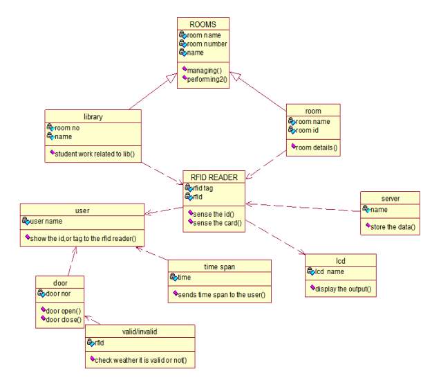
FIG 5.5.2 CLASS DIAGRAM
The above diagram represents the class diagram of our system i.e., it shows various classes used in our system and the relationship with one class to other in the system. Each rectangle box represents a class and the upper portion of it represents the class name and middle portion represents attributes of the class and the lower represents the functions performed by that class.
5.5.3 SEQUENCE DIAGRAM
A sequence diagram is a diagram where various objects interact with one another in a sequence order of a system.
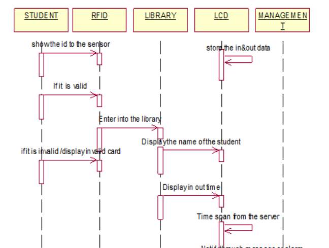
FIG 5.5.3 SEQUENCE DIAGRAM
The above diagram portrays about the sequence diagram of the system where objects interact with each other with respect to the sequence of the time. Rectangular box represents the object, dashed lines (vertical) represents the object life time and arrows the flow of data from one object to other.
5.5.4ACTIVITY DIAGRAM:
Activity diagrams represent the flow between various activities of the system in the form of a diagram. It looks like a flow chart.
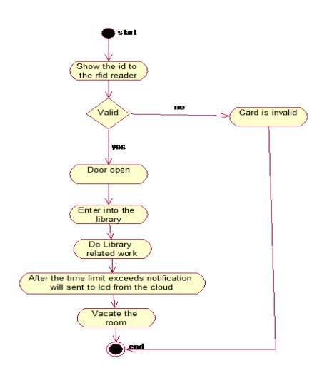
FIG 5.5.4..ACTIVITY DIAGRAM
The above diagram portrays about the activity diagram of the system i.e., it represents the flow of activities in our project. The dot at the start represents starting of a system and dot with circle represents the ending of a system and an activity is represented as curve sided rectangle. On seeing it we can understand the flow activities that has to be gone from start to end.
6. CODING AND SYSTEM TESTING
6.1. CODING:
6.1.1.CRITICAL ROOM:
#include <RFID.h>
* Read a card using a mfrc522 reader on your SPI interface
* Pin layout should be as follows (on Arduino Uno):
* MOSI: D7 / ICSP-4
* MISO: D6 / ICSP-1
* SCK: D5 / ISCP-3
* SS/SDA: D4
* RST: Pin D2
#include <ESP8266WiFi.h> // include the library code:
#include <LiquidCrystal.h>
#include <SoftwareSerial.h>
SoftwareSerial lcd(D1, D3);
#include <SPI.h>
#include <RFID.h>
#include <Servo.h>
Servo myservo;
#define SS_PIN D4
#define RST_PIN D2
RFID rfid(SS_PIN,RST_PIN);
WiFiClient client;
const char* ssid = “Connectify-snist”;
const char* password = “19july,1995”;
String RoomKey = “1488880945”;
const char* host = “smartsecurityrfid.thesmartbridge.com”;
int serNum[5];
int Card1_Status = 0 ;
int Card2_Status = 0 ;
int Card3_Status = 0 ;
int Card_Status;
String cancat_card = ” “;
String Card1 = “32,169,188,79,122”;
String Card2 = “166,177,38,59,10”;
String Card3 = “195,160,38,59,126”;
int flag = 0 ;
bool access = false;
void setup() {
Serial.begin(9600);
SPI.begin();
rfid.init();
myservo.attach(D0);
myservo.write(0);
lcd.begin(9600);
delay(1000); // We start by connecting to a WiFi network
Serial.println();
Serial.println();
Serial.print(“Connecting to “);
Serial.println(ssid);
WiFi.begin(ssid, password);
while (WiFi.status() != WL_CONNECTED){
delay(500);
Serial.print(“.”);}
Serial.println(“”);
Serial.println(“WiFi connected”);
Serial.println(“IP address: “);
Serial.println(WiFi.localIP());}
void loop(){
if(rfid.isCard()){
if(rfid.readCardSerial()){
Serial.print(rfid.serNum[0]);
Serial.print(” “);
Serial.print(rfid.serNum[1]);
Serial.print(” “);
Serial.print(rfid.serNum[2]);
Serial.print(” “);
Serial.print(rfid.serNum[3]);
Serial.print(” “);
Serial.print(rfid.serNum[4]);
Serial.println(“”);
Cancat_card=String(rfid.serNum[0])+”,”+String(rfid.serNum[1])+”,”+String(rfid.serNum[2])+”,”+String(rfid.serNum[3])+”,”+String(rfid.serNum[4]);
if(cancat_card == Card1){
access = true;
if(Card1_Status == 0){
Card1_Status = 1 ;
Card_Status = Card1_Status ;
cancat_card =”32,169,188,79,122″;
RoomKey = “1488880945”;
Serial.println(“Card Id = “+cancat_card+” == Welcome == it is Card 1 “);
upload(cancat_card ,RoomKey,Card_Status );
//delay(1000);
myservo.write(180);
delay(1500);
myservo.write(0);}
else{
Card1_Status = 0 ;
Card_Status = Card1_Status ;
cancat_card =”32,169,188,79,122”;
RoomKey = “1488880945”;
Serial.println(“Card Id = “+cancat_card+” == Bye == it is Card 1″);
upload(cancat_card ,RoomKey,Card_Status );
myservo.write(180);
delay(1500);
myservo.write(0);}}
else if(cancat_card == Card2){
access = true;
if(Card2_Status == 0){
Card2_Status = 1 ;
Card_Status = Card2_Status ;
cancat_card =”166,177,38,59,10″;
RoomKey = “1488880945”;
Serial.println(“Card Id = “+cancat_card+” == Welcome == it is Card 2″);
upload(cancat_card ,RoomKey,Card_Status );
//delay(1000);
myservo.write(180);
delay(1500);
myservo.write(0);}
else{ Card2_Status = 0 ;
Card_Status = Card2_Status ;
cancat_card =”166,177,38,59,10″;
RoomKey = “1488880945”;
Serial.println(“Card Id = “+cancat_card+” == Bye == it is Card 2″);
upload(cancat_card ,RoomKey,Card_Status );
//delay(1000);
myservo.write(180);
delay(1500);
myservo.write(0);
}
}
else if(cancat_card == Card3)
{
access = true;
if(Card3_Status == 0)
{
Card3_Status = 1 ;
Card_Status = Card3_Status ;
cancat_card =”195,160,38,59,126″;
RoomKey = “1488880945”;
Serial.println(“ROOM 2”);
Serial.println(“Card Id = “+cancat_card+” == Welcome == it is Card 3″);
upload(cancat_card ,RoomKey,Card_Status );
// delay(1000);
myservo.write(180);
delay(1500);
myservo.write(0);
}
else
{
Card3_Status = 0 ;
Card_Status = Card3_Status ;
cancat_card =”195,160,38,59,126″;
RoomKey = “1488880945”;
Serial.println(“Card Id = “+cancat_card+” == Bye == it is Card 3″);
upload(cancat_card ,RoomKey,Card_Status );
myservo.write(180);
delay(1500);
myservo.write(0);
} }
else
{
Serial.println(“Cancat Id = “+cancat_card);
Serial.println(“=== Invalid Card ===”);
access = false;
delay(1000);
}}}
getTalkBack();
rfid.halt();
}
void upload( String cancat_card ,String RoomKey, int Card_Status )
{
Serial.print(“connecting to “);
Serial.println(host);
// Use WiFiClient class to create TCP connections
WiFiClient client;
const int httpPort = 80;
if (!client.connect(host, httpPort))
{
Serial.println(“connection failed”);
return;
}
// We now create a URI for the request
String url=”&field1=”;
url += cancat_card;//card no
url += “&field2=”;
url += RoomKey;//room no
url += “&field3=”;
url += Card_Status;//card status
url=”/API/access?”+url;
client.print(String(“GET “) + url + ” HTTP/1.1 ” +”Host: ” + host + “ ” + “Connection: close ”);
unsigned long timeout = millis();
while (client.available() == 0) {
if (millis() – timeout > 1000) {
Serial.println(“>>> Client Timeout !”);
client.stop();
return;
}
}
if (client.find(“@@”))
{
String Display = client.readStringUntil(‘ ’);
Serial.println(Display);
}
delay(10);
Serial.println();
Serial.println(“closing connection”);
}
void getTalkBack()
{
String tsData=”/API/timeout”;
if (client.connect(“smartsecurityrfid.thesmartbridge.com”, 80))
{
client.print(String(“GET “) + tsData + ” HTTP/1.1 ” +”Host: ” + host + “ ” + “Connection: close ”);
unsigned long timeout1 = millis();
while (client.available() == 0) {
if (millis() – timeout1 > 1000) {
Serial.println(“>>> Client Timeout !”);
client.stop();
return;
}}}
String Display = client.readStringUntil(‘ ’);
Serial.println(Display);
if(client.find(“@@”))
{
String Display = client.readStringUntil(‘ ’);
Serial.println(Display);
lcd.println(Display);
lcd.println();
}}
6.1.2.LCD:
/*
The circuit:
* LCD RS pin to digital pin 12
* LCD Enable pin to digital pin 11
* LCD D4 pin to digital pin 5
* LCD D5 pin to digital pin 4
* LCD D6 pin to digital pin 3
* LCD D7 pin to digital pin 2
* LCD R/W pin to ground
* 10K resistor:
* ends to +5V and ground
* wiper to LCD VO pin (pin 3)
*/
// include the library code:
#include <LiquidCrystal.h>
#include <SoftwareSerial.h>
SoftwareSerial mySerial(8,9);
String Display;
// initialize the library with the numbers of the interface pins
LiquidCrystal lcd(12, 11, 5, 4, 3, 2);
void setup(){ // set up the LCD’s number of columns and rows:
Serial.begin(9600);
mySerial.begin(9600);
lcd.begin(16, 2);
delay(1000); }
void loop()
{
for (int positionCounter = 0; positionCounter < 29 ; positionCounter++) {
// scroll one position left:
lcd.scrollDisplayLeft(); // wait a bit:
delay(1000);
}
if (mySerial.available()>0)
{
String Display = mySerial.readString();
Serial.println(Display);
lcd.setCursor(0, 1);
lcd.print(Display);
}
}
6.1.3.API ‘S:
<?php
defined(‘BASEPATH’) OR exit(‘No direct script access allowed’);
class API extends CI_Controller {
public function __construct(){
parent::__construct();
$this->load->model(‘API_model’);
header(“Access-Control-Allow-Orgin: *”);
date_default_timezone_set(“Asia/Calcutta”);
} public function index(){
redirect(base_url());}
public function access() {
// print_r($_GET);die;
if($this->input->get()) {
// !! API Description
// !! field1 –>> Card Id / Card Number
// !! field2 –>> Roome Key
// !! field3 –>> Flag for Entry or Exit , 1 –> Entry and 0 –> Exit
// !! sample API
$field1= ”;
$field2= ”;
$field3= ”;
if($this->input->get(‘field1’))
$fiedl1 = trim($this->input->get(‘field1’));
if($this->input->get(‘field2’))
$field2 = trim($this->input->get(‘field2’));
if($this->input->get(‘field3’))
$field3 = trim($this->input->get(‘field3’)); // Check Card Nummber In Or Records
$check1 = $this->API_model->check_cardId($fiedl1);
if($check1[‘err’] == 1) { // Check Room Key withn our records
$check2 = $this->API_model->check_room($field2);
if($check2[‘err’] == 1){ // Check Allow In Reqired Room
if($check2[‘criticalroom’] == 1){
if($check1[‘criticalroom’] == 1){
$responce = $this->API_model->Insert_record($fiedl1,$field2,$field3);
if($responce[‘err’] == 0){
echo”@@INVALIDENTRY”;}
else{
if($field3 == 0)
echo “@@Total Time Spend “.$responce[‘spend_time’];
else
echo”@@SUCCESSFULLY ENTERED “; } }
else{
echo “@@ACCESS DENIED”;}
else{
$responce = $this->API_model->Insert_record($fiedl1,$field2,$field3);
if($responce[‘err’] == 0) {
echo “@@INVALID ENTRY”; }
else{
if($field3 == 0)
echo “@@Total Time Spend = “.$responce[‘spend_time’];
else
echo “@@SUCCESSFULLY ENTERED “; }}}
else
echo “@@INVALID ROOM KEY”; }
else
echo “@@INVALID CARD NUMBER”;}}
public function timeout() {
$res = $this->API_model->timeout();
if($res == ”)
$res = ‘…WELCOME …’;
else
$res .= $res.’ please vacate the room’;
echo “@@”.$res;die;}}
ii) <?php if ( ! defined(‘BASEPATH’)) exit(‘No direct script access allowed’);
require_once(APPPATH.’models/Common_model.php’);
class API_model extends Common_model {
public function __construct() {
parent::__construct();
date_default_timezone_set(“Asia/Calcutta”); }
public function check_cardId($cardId)
{
// Check Card Id In Our Records
$cardId = trim($cardId);
$this->db->select(‘*’);
$this->db->from(‘ss_db_Users’);
$this->db->where(‘CardId’,$cardId);
$row = $this->db->get()->row_array();
if(!empty($row))
{
return array(‘err’=>1,’criticalroom’=>$row[‘CriticalRoom’]);
}
else
return array(‘err’=>0);
}
public function check_room($roomkey)
{
// Check Room Key withn our records
$RoomKey = trim($roomkey);
$this->db->select(‘*’);
$this->db->from(‘ss_db_Rooms’);
$this->db->where(‘RoomKey’,$RoomKey);
$row = $this->db->get()->row_array();
if(!empty($row))
{
return array(‘err’=>1,’criticalroom’=>$row[‘CriticalRoom’]);
}
else
return array(‘err’=>0);
}
public function Insert_record($field1,$field2,$field3)
{
$this->db->select(‘*’);
$this->db->from(‘ss_db_Users’);
$this->db->where(‘CardId’,$field1);
$row = $this->db->get()->row_array();
$this->db->select(‘*’);
$this->db->from(‘ss_db_Rooms’);
$this->db->where(‘RoomKey’,$field2);
$row1 = $this->db->get()->row_array();
if($field3 == 1) {
$data[‘CardId’] = $field1;
$data[‘UserId’] = $row[‘UserId’];
$data[‘RoomId’] = $field2;
$data[‘CriticalRoom’] = $row[‘CriticalRoom’];
$data[‘EntryFlag’] = 1;
$data[‘EntryDate’] = date(‘d M Y’);
$data[‘EntryTime’] = date(‘h:i a’);
$data[‘EntryDate_Time’] = date(‘Y-m-d h:i:s’);
$data[‘RecordDate’] = date(‘Y-m-d h:i:s’);
$this->db->insert(‘ss_db_api_records’,$data);
return array(‘err’=>1) ;}
else{
$this->db->select(‘*’);
$this->db->from(‘ss_db_api_records’);
$this->db->where(‘CardId’,$field1);
$this->db->where(‘RoomId’,$field2);
$this->db->where(‘EntryFlag’,1);
$this->db->where(‘ExitFlag’,”);
$this->db->order_by(‘RecordId’,’desc’);
$all_res = $this->db->get()->row_array();
if(!empty($all_res)){
$recordId = $all_res[‘RecordId’];
$entry_time = $all_res[‘EntryDate_Time’];
$exit_time = date(‘Y-m-d h:i:s’);
$data[‘ExitFlag’] = 1;
$data[‘ExitDate’] = date(‘d M Y’);
$data[‘ExitTime’] = date(‘h:i a’);
$data[‘ExitDate_Time’] = date(‘Y-m-d h:i:s’);
$spend_time = ”;
$start_date = new DateTime($entry_time);
$since_start = $start_date->diff(new DateTime($exit_time));
if($since_start->y != 0)
$spend_time .= $since_start->y.’ years ‘ ;
if($since_start->m != 0)
$spend_time .= $since_start->m.’ months ‘;
if($since_start->d != 0)
$spend_time .= $since_start->d.’ days ‘;
if($since_start->h != 0)
$spend_time .= $since_start->h.’ hours ‘;
if($since_start->i != 0)
$spend_time .= $since_start->i.’ minutes ‘;
if($since_start->s != 0)
$spend_time .= $since_start->s.’ seconds ‘;
$data[‘SpendTime’] = $spend_time ;
$this->db->where(‘RecordId’,$recordId);
$this->db->update(‘ss_db_api_records’,$data);
return array(‘err’=>1,’spend_time’=>$spend_time) ; }
else
return array(‘err’=>0) ;}}
public function timeout()
{
$rows = $this->db->query(‘select * from ss_db_api_records where EntryFlag = 1 and ExitFlag != 1 ‘)->result_array();
$names = ”;
foreach($rows as $row)
{
$spend_time = ”;
$entry_time = $row[‘EntryDate_Time’];
$exit_time = date(‘Y-m-d h:i:s’);
$start_date = new DateTime($entry_time);
$since_start = $start_date->diff(new DateTime($exit_time));
if(intval($since_start->i) > 5)
{
$this->db->select(‘*’);
$this->db->from(‘ss_db_Users’);
$this->db->where(‘UserId’,$row[‘UserId’]);
$users_data = $this->db->get()->row_array();
$names .= $users_data[‘FirstName’].’ ‘.$users_data[‘LastName’].’ ,’; }}
return $names ; }}
?>
6.2. SYSTEM TESTING:
The purpose of testing is to discover errors. Testing is the process of executing a program or application to locate every conceivable fault or bugs. It allows a way to check the usage of components, sub-assemblies, assemblies and/or a finished product. It is the method of exerting software with the intent of ensuring that the product meets its requirements and user expectations and does not fail in an unsatisfactory manner. There are various types of test. Each test type addresses a specific testing requirement.
6.2.1 TYPES OF TESTS
1. Unit testing
Unit testing is the testing of individual modules of a software product where the test cases formed by testers not only used to verify and validate the program output but also the verifies the internal functional logic. This is the structural testing where the product testers should have in depth knowledge on the process and verify the logic. It comes under white box testing where the tester should understand the code. Unit test is performed at individual module level where it is ensured that process provides outcome accurately and also according to the specifications with defined inputs and expected results.
2. Integration testing
Integration testing is the testing performed after the unit testing of different modules of a software product where we integrate the different modules .Then theses modules are verified and validated to check whether any problem arises from combination of modules or any changes occurred in the functional logic.
3. Functional test
Functional testing is the testing performed to verify and validate the features of the software product ,whether they are according to the design ,specifications provided.
- Valid Input : valid input helps in identifying classes those classes must be accepted.
- Invalid Input : invalid input helps in identifying classes those classes must be rejected.
- Functions : functions which are identified must be utilized.
- Output : outputs which are identified in application must be utilized.
- Systems/Procedures : linking systems or procedures must be called.
Functional testing is mainly focused on the system requirements, problems that occur rarely in the form of test cases. Before performing the functional testing ,other test are detected and current result are resolved and decided.
4. System Test
System test is the test which is performed on the whole software system where it is ensured that the system meets the requirements or not. It mainly depends on integration testing where we consider integration points.
5. White Box Testing
White Box Testing is also known as code based testing. In this type of testing ,the tester has the in-depth knowledge of what implementation is performed ,what are the method used, what is the design ,what are the specifications of software system.
6.2.2 Unit Testing:
Unit testing is the testing which is performed on a unit module and it is said to be part of a whole code of a software system. Unit testing is performed as two phases.
Test strategy and approach
Unit testing will be performed manually using field testing where we test in which environment it is used and the output is determined. Functional tests will be prescribed.
Test objectives
• All fields must work properly.
• Pages must be activated only through the identified link.
• There must be no delay in the responses, messages.
Features to be tested
• All the entries must be verified to be in the incorrect format.
• Duplicate values shouldn’t be allowed
• Links in the system must be directed to expected destination in the system.
Unit Testing results:
| S.No | Testcase
ID |
Input | Expected
Output |
Actual
Output |
Remarks | Results |
| 1. | UT_01 | Admin login & password are entered. | Successfully entered. | Successfully entered. | Login details of admin are entered. | Passed. |
| 2. | UT_02 | Checking whether new user details are entered. | New user Details are updated. | New user details are updated. | Data has been updated successfully. | Passed. |
| 3. | UT_03 | Checking whether New rooms are entered. | New rooms details are updated. | New rooms details are updated. | Data has been updated successfully. | Passed. |
| 4. | UT_04 | Checking whether new user details are entered. | New user Details are updated. | New user details are not updated. | Data has not been updated successfully. | Failed. |
| 5. | UT_03 | Checking whether New rooms are entered. | New rooms details are updated. | New rooms details are not updated. | Data has not been updated successfully. | Failed. |
All the test cases mentioned above passed successfully. No defects encountered.
6.2.3 Integration Testing
Integration testing is the testing where we combine two or more software system modules/components on the same platform to verify if there is any chance of failures due to interfaces. The main responsibility of integration testing is to check whether the components interact without any error.
Integration testing results:
| S.No | Testcase
ID |
Input | Expected
Output |
Actual
Output |
Remarks | Results |
| 1. | IT_01 | Admin login & password are entered. | Successfully entered & redirected to dashboard page. | Successfully entered & redirected to dashboard page. | Login details of admin are entered. | Passed. |
| 2. | IT_02 | Admin login & password are entered. | Successfully entered & redirected to dashboard page. | Admin login and password details are wrong. | Login details of admin are entered. | Failed. |
| 4. | IT_04 | Checking whether RFID reader detects the id card or not. | Successfully detected and shows info in dashboard page. | Invalid card . | Id card has been verified successfully. | Passed. |
| 5. | IT_05 | Checking whether RFID reader detects the id card or not. | Successfully detected and shows info in dashboard page. | Connecting to wifi and details not updated in the dashboard page | Id card has not been verified successfully. | Failed. |
Test Results: All the test cases mentioned above passed successfully. No defects encountered.
6.2.4Acceptance Testing
Acceptance testing is a crucial phase testing where it is verified by the participation of end user. In this testing, the software system should be verified whether it meets the requirements provided or not.
| S.No | Test case
ID |
Input | Expected
Output |
Actual
Output |
Remarks | Results |
| 1. | T_01 | Admin login & password are entered & checks the manage employees and rooms page. | Successfully entered & redirected to dashboard page. | Successfully entered & redirected to dashboard page. | Login details of admin are entered. | Passed. |
| 2. | T_02 | Admin login & password are entered & checks the manage employees and rooms page. | Successfully entered & redirected to dashboard page. | Successfully not entered | Login details of admin entered are incorrect. | Failed. |
| 3. | T_03 | Checking whether RFID reader detects the id card or not. | Successfully detected, shows info in dashboard page and in the serial monitor. | Successfully detected, shows info in dashboard page and in the serial monitor. | Id card has been verified successfully. | Passed. |
| 4. | T_04 | Checking whether RFID reader detects the id card or not. | Successfully detected and shows info in dashboard page. | Connecting to wifi and details not updated in the dashboard page | Id card has not been verified successfully. | Failed. |
| 5. | T_05 | Checking whether RFID reader detects the id card or not. | Successfully detected and show info in dashboard page. | Successfully detected and details not updated in the dashboard page | Id card has been verified successfully but not updated. | Failed. |
| 6. | T_06 | Checking whether RFID reader detects the id card or not | Successfully detected | Successfully detected but access denied | Id card has been verified successfully but access denied. | Passed. |
| 7. | T_07 | Checking whether RFID reader detects the id card and displays in the LCD display. | Successfully detected and shows info in dashboard page. Displays in the LCD display | Successfully detected, details updated in the dashboard page & displays in the LCD display | Id card has been verified successfully & display in the LCD display. | Passed. |
Test Results: All the test cases mentioned above passed successfully. No defects encountered
7. RESULTS AND ANALYSIS
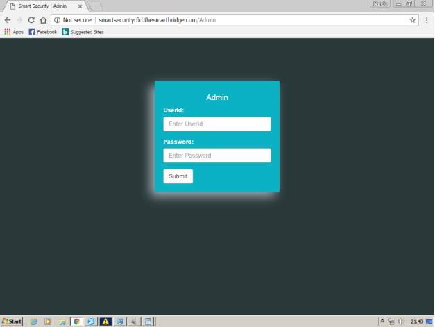
FIG 7.1 ADMIN LOGIN PAGE
After opening the website admin needs to login with credentials.
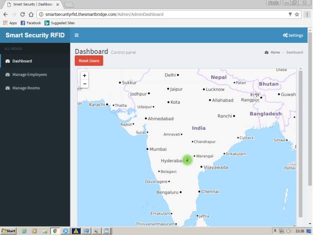
FIG 7.2 MAIN HOME PAGE
This is the main home page where admin can check the employees in and out of the rooms in the map located which indicates the rooms present in the industry and employees present in that room.
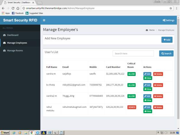
FIG 7.3 EMPLOYEE DETAILS
On pressing manage employees button .Here admin can add,delete,give access to rooms like critical,normal operations on the employees data where each employee is provided with unique identity number and other details like name,email,mobile number.
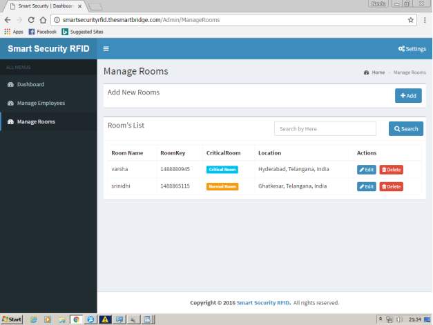
FIG 7.4 MANAGE ROOMS
On clicking manage rooms admin can create,delete the rooms where each room is created with a key,location,room access whether its critical or normal or any other by specifying room names.
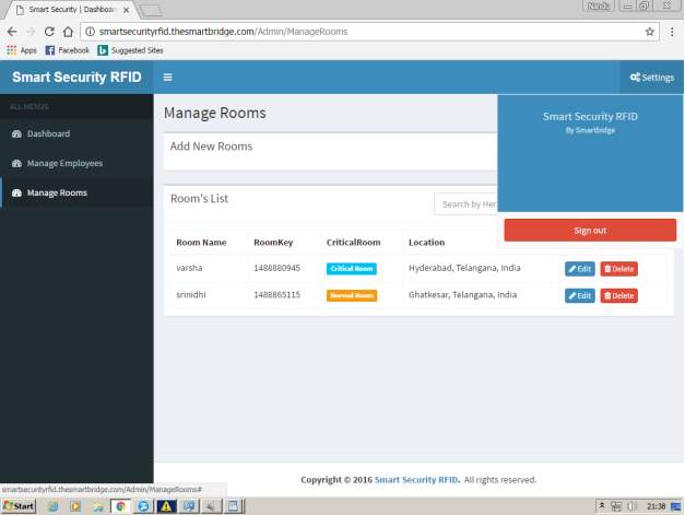
FIG 7.5 SIGNOUT PAGE
On clicking settings, admin can signout .
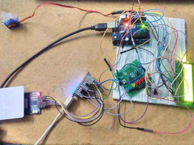
FIG 7.6.ID CARD DETECTION AND VALIDATION
This image shows how to detect a card under the reader when it is inserted and validation of card is performed.
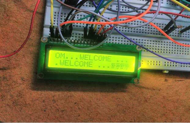
FIG 7.7.LCD DISPLAY
This image shows whenever a person enters into by inserting a card .It is displayed through LCD that he is welcomed to enter in.
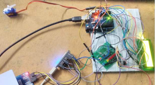
FIG 7.8 LCD DISPLAY-2
This image shows whenever user is needed to exit from the critical room after particular time. He is alarmed through the display by a message whenever client time is out the client need to exit from the room.
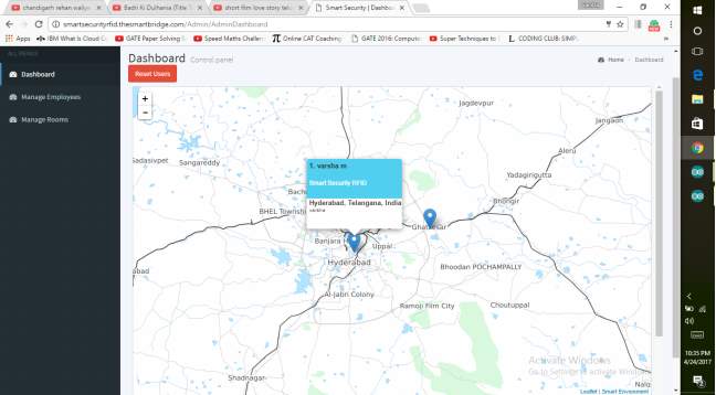
FIG 7.9 MAP DISPLAY
This image represents whenever a person enters it is shown in the website by indicating rooms in map to the admin. Admin gets to know whoever is there in the room through the site.
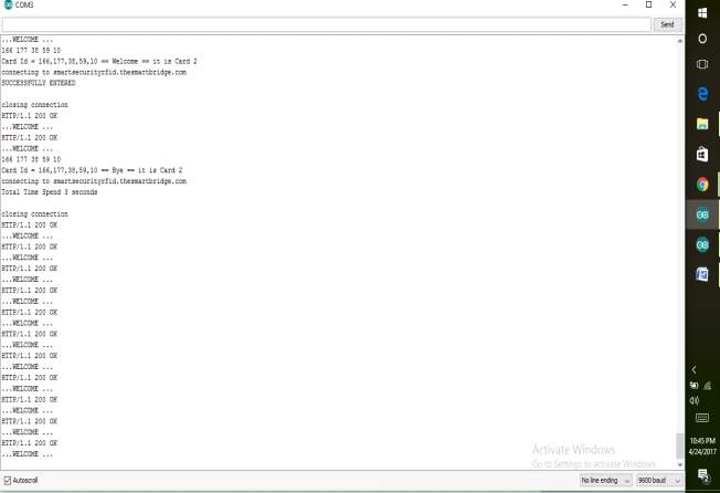
FIG 7.10. TIME DISPLAY
This image shows whenever a person exits the admin gets to know the data of the time worked with the IDname, number. It also shows whenever a card is inserted it shows the details of the card and the person.
8. CONCLUSION
This report is to ensures how we can provide security for large industries where there are number of people working by the help of RFID reader where it captures the data from the card given to the employee when inserted near the reader by matching a frequency level where magnetic waves are generated and so the data is transmitted from the card when the frequency level matches followed by opening of the door if valid card or else invalid. This project can be further extended in order to provide high security by assigning passwords, biometric or finger print .It is helpful to gather the data of employee time in and out, by limiting access to the members in to confidential rooms where there is a particular time assigned to stay as soon as the time is out employee will be alerted through the liquid crystal display. Therefore it’s helpful for large industries.
9. FUTURE SCOPE
Day-by-day the population is increasing so their will be more number of employees working proportionally so there is a need of this technology as many people work, there should be proper authentication of employees in order to maintain security because every industry as to maintain confidentiality Hence there is a scope for the poject.
This project can be further extended in order to provide high security as security plays a major role nowadays because there is scope for huge amount of data than present so in order to overcome to protect from various cyber attacks security plays a major role so there is a scope for the project extension by assigning passwords to the identity cards provided ,by biometric assurance,iris assurance of people and also by providing additional features,
BIBLIOGRAPHY
References:
- The Joy of PHP Programming: A Beginner’s Guide – by Alan Forbes
- PHP & MySQL Novice to Ninja – by Kevin Yank
- V. Cardellini, M. Colajanni, and P. S. Yu. Dynamic load balancing on web-server systems. IEEE Internet Computing, 3(3):28{39, 1999.
- L. Cherkasova. FLEX: Load Balancing and Management Strategy for Scalable Web Hosting Service. IEEE Symposium on Computers and Communications, 0:8, 2000.
- R. Fielding, J. Gettys, J. Mogul, H. Frystyk, L. Masinter, P. Leach, and T. Berners-Lee. Hypertext transfer protocol { http/1.1. In IETF RFC 2616, 1999.
Referred links:
- Code igniter framework. https://www.tutorialspoint.com/codeigniter/codeigniter_quick_guide.htm
- D3 js . https://d3js.org/
- d3 js. https://github.com/d3/d3/wiki/Gallery
- Arduino Ide .https://www.arduino.cc/en/main/software
- https://www.javascript.com/E.HYPERLINK “https://www.javascript.com/E.Sites”Sites
- PHP. http://php.net/manual/en/intro-whatis.php
- https://www.arduino.cc/
- https://thingspeak.com/
- https://www.arduino.cc/en/Tutorial/HomePage
Cite This Work
To export a reference to this article please select a referencing stye below:
Related Services
View all


Related Content
All TagsContent relating to: "Technology"
Technology can be described as the use of scientific and advanced knowledge to meet the requirements of humans. Technology is continuously developing, and is used in almost all aspects of life.
Related Articles

DMCA / Removal Request
If you are the original writer of this dissertation and no longer wish to have your work published on the UKDiss.com website then please: