Exhaust Gas Recirculation System to Reduce diesel Engine Emissions
Info: 13346 words (53 pages) Dissertation
Published: 13th Dec 2019
Tagged: AutomotiveEnergy
Way to Reduce diesel engine emissions
- Contents
2.4.1 A breakdown of Euro Emission Standards
3.1.1 NOx production mechanisms
3.2.1 Water Injection In diesel combustion
3.2.2 Selective Catalyst reduction
3.2.3 Exhaust Gas Recirculation System
3.3 Analysis and Interpretation of an EGR flow system
4.1 Bus and Engine specifications
5.1 Engine Performance and Emission Analysis on EGR usage
2. Introduction
Today, diesel engines are the backbone of the commercial transport industry used in trucks, ships, buses, etc. to transport goods from one place to another. They are also used to generate electricity and to power mobile/stationary equipment. They have gained popularity because of their better fuel economy and high power producing capabilities at lower maintenance costs. In recent years, a record number of diesel cars sales has been observed. Compared to gasoline engines diesel engines are more durable, reliable and consumes less fuel. They also have significantly less carbon monoxide and hydrocarbon emissions. But at the same time higher NOx (Nitric Oxide) and soot emission levels remains an environmental concern. These hazardous pollutants are responsible for several environmental as well as health problems. NOx emissions are responsible for the ozone and smog formation while soot can cause reduced visibility and when inhaled can cause several fatal lung diseases. Therefore, there is an urgent need for carmakers to come up with technologies that can efficiently reduce these emission without compromising with engine performance. [1] [3]
Apart from this, latest emission legislation (Euro 6) has also forced automakers to develop new technologies which can combat these exhaust emissions.
In this thesis an extensive research has been done on various emission reduction strategies. Out of those strategies, Exhaust Gas Recirculation system has been analysed and studied extensively. The effects of increasing EGR rates on engine performance and emissions have been observed and evaluated.
2.1 The diesel engine

Figure 1: A diesel engine [13]
Diesel engine is a type of internal combustion engine where the fuel is ignited spontaneously under high temperature and pressure conditions in the combustion chamber. This is why they are often called compression ignition engines. A diesel engine can be naturally aspirated in which atmospheric air is inducted, it can turbocharged which uses an exhaust driven turbine-compressor combination to compress the inlet air or it can be supercharged engine in which inlet is compressed with the help of mechanically driven pump or blower.
A diesel engine essentially consist of following main components:
- the piston, a mechanical component which converts pressure generated by the gases into oscillating movement,
- the cylinder, which the limits the movement of the piston and provide the room for combustion to take place,
- the connecting rod, which connects piston to crankshaft and transmits power from the piston to the crankshaft,
- the injector, which is there to inject the fuel in the combustion chamber,
- The crankshaft, which converts reciprocating motion of piston into rotational motion.
High compression ratios (12-24) are used in diesel engines to compress inducted air, fuel is injected just before the TDC (top dead centre) as a high pressure spray using different injection systems and pressures depending on the power output and the size of the engine. The most commonly used injection systems are:
- unit injectors, fitted in cylinder head and are driven by camshaft,
- Common rail fuel system, a common fuel rail is used fed pressurized fuel to the injectors.
In standard conditions, a diesel combustion can be characterised a lean combustion as air fuel ratio (AFR) is much higher than the stoichiometric AFR (14.5:1). That means, the amount of air ingested into the combustion chamber is much more than what is required for a complete combustion. High proportion of the air is required as diesel is a viscous fuel and requires higher ignition temperatures. [12]
2.2 Diesel Engine Combustion
The diesel engine is type of internal combustion engine which harnesses the chemical energy of fuel and converts it into useful mechanical work. It uses a 4 stroke cycle in which fresh air is taken in (Intake stroke) and is compressed under high pressure and temperatures (Compression stroke). The fuel injection systems inject liquid fuel as one or more jets through small nozzles at high velocities into the combustion chamber near the end of compression stroke. The liquid fuel atomizes into small drops and subsequently vaporizes and mixes with the high-temperature, high-pressure cylinder air. As the piston moves towards top dead centre the temperature of the surrounding rise above fuel ignition temperature. Instantaneous ignition of already mixed fuel and air occurs after an ignition delay period of few crank angles degrees. This spontaneous ignition marks the start of combustion and the end of ignition delay period. The gas expands after ignition and move the piston downwards thus generating output (Expansion Stroke). The burnt mixture in discharged in the Exhaust Stroke. [2] [5]
The combustion process in a diesel engine is a complex one and takes place in four different stages.
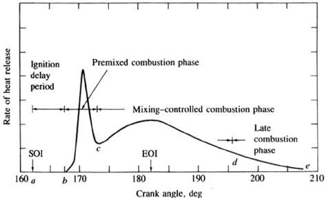
Figure 2: Direct Ignition diesel engine heat-release-rate diagram
Indicating different combustion stages. [2]
Ignition delay period (a-b)
The combustion process doesn’t start immediately just after the fuel injection into the combustion chamber. The time period between the start of fuel injection and the start of combustion (SOC) is called ignition delay period. The fuel gets mixed with air during the ignition delay period.
Premixed Combustion Phase (b-c)
The portion of the pre mixed air-fuel mixture that is within the flammability limits gets ignited in this phase and combustion occurs. High heat release rates are characteristic of this phase.
Mixing-controlled combustion (c-d)
After the premixed air-fuel mixture gets consumed, the heat release rate becomes dependant on the rate at which mixture is available for burning. The rate of burning in this region is predominantly controlled by fuel vapour-air mixing process.
Late combustion Phase (d-e)
In this phase the heat release continues in the expansion stroke but at a very lower rates. This low heat release is due to the unburned fuel which may not have yet burned. Soot particles and combustion products also contain a small fraction of fuel energy which can released. [2]
2.3 Diesel Engine emissions
Like most of the fossil fuels, diesel fuel is made up of carbon and hydrogen. The average chemical formula for a common diesel fuel is C12H23. [4] Ideally, complete combustion of diesel fuel would only generate CO2 and H2O in the combustion chamber of diesel engines. However, many factors such as ignition timing, the air-fuel ratio, turbulence, combustion temperature, etc. influence the combustion process and a number of harmful products gets generated.
Diesel Engine exhaust primarily consist of four main pollutants which are Unburned hydrocarbons (HC), Carbon monoxide (CO), Particulate matter (PM) and oxides of Nitrogen (NOx). [3]
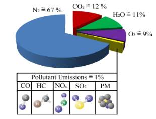
Figure 3: Composition of diesel exhaust [3]
As it is can be seen from figure 2, pollutant emission are less than 1% of the diesel exhaust in conventional DI diesel engines. Among all the pollutants NOx has the highest proportion in pollutant emission followed by soot which is produced because of the lean condition of the diesel combustion. The production of HC and CO is also minimal because of the same reason. SO2 is also produced in small proportion because of the sulphates present in the diesel fuel. Ultra-low sulphur diesel (ULSD) is used nowadays to prevent effects of SO2. [3]
Air Fuel Ratio of a diesel engine
The formation of the pollutants largely depends on the Air-Fuel ratio (AFR) of the engine. AFR is the ratio of air consumed by the engine compared to the amount of fuel. When the amount of air and fuel in enough to produce a chemically complete combustion reaction then the ratio is called stoichiometric AFR. For diesel engines stoichiometric AFR has 14.5 parts of air for each part of fuel (14.5:1). An engine can either have a lean or a rich combustion. If AFR number is less than the stoichiometric AFR (<14.5:1), it means less air during combustion and engine runs in rich condition. Contrarily, if an AFR number is higher than the stoichiometric AFR (>14.5:1), it means more air and the engine runs in lean condition.
Lean combustion is characteristic of a diesel engine. [3]
2.3.1 Carbon Monoxide (CO)
Carbon monoxide formation largely depends on the Air-fuel ratio (AFR). If the engine runs on rich condition (i.e. less air) during the combustion, then due to the deficiency of air in the combustion chamber incomplete oxidation occurs and a large proportion of carbon is unable to get converted into CO2.
Diesel engines are lean combustion engine so CO is produced in very small proportions.
Carbon monoxide is an odourless and colourless gas which when inhaled binds with haemoglobin and reduces its capacity to transfer oxygen. It can affect function of different organs and can result in confusion, light-headedness, headache and impaired concertation. In the worst case Carbon monoxide poisoning can even lead to death. [3]
2.3.2 Hydrocarbons (HC)
Hydrocarbons are the outcome of the incomplete combustion of the hydrocarbon fuel. Air-fuel mixture temperature near the wall in combustion chamber is significantly less than the centre of the cylinder. Because of this flame quenching occurs at the walls of the cylinder and a small proportion of fuel remain unburned. This leads to the formation of hydrocarbons. Hydrocarbons in diesel exhaust contains a lots of species, such as alkanes, alkenes and aromatics. Some of these species are inert while others are highly reactive and contributes in the smog formation.
Diesel combustion normally produce low levels of hydrocarbon.
Due to lean combustion in diesel engines sometimes the flame speed is too low to complete the combustion and in some parts of the combustion chamber, combustion doesn’t even occur. These conditions cause high HC emissions.
Hydrocarbons can be harmful and cause environmental and health problems. They are toxic and can cause respiratory tract irritation and can even cause cancer. They can produce smog and cause acid rain. [2] [3]
2.3.3 Nitric Oxide (NOx)
Oxides of nitrogen, NO and NO2 are collectively referred as NOx. In a diesel exhaust NO constitutes of about 85 – 90% of NOx. After its emission, NO reacts with atmospheric air to form NO2. NO is a colourless and odourless gas while NO2 has reddish brown colour with pungent smell.
The amount of NOx produced during combustion largely depends on the maximum temperature in the cylinder, concentrations of the oxygen and the residence time. Highly compressed hot air is used in diesel combustion to ignite the fuel. This atmospheric air contains Nitrogen and Oxygen. Normally Nitrogen does not take part in the combustion process and remains unreacted throughout the combustion process. However, if in cylinder temperatures reaches to around 1600°C, it causes nitrogen to react with oxygen and generate NOx emissions. Most of the NOx is produced early in the combustion process when the flame temperature is the maximum. Therefore NOx emission increases with the increase in temperature in the combustion chamber.
Road transport contributes to 40 – 70% of the worldwide NOx and among all the vehicles types diesel vehicles are the main contributors to NOx emissions. 85% of all the NOx emissions from all the mobile sources comes from diesel operated vehicles.
Nitrogen oxide emissions are responsible for several environmental and health problems. These emissions are the cause of acidification, formation of ozone, smog formation, acid rains etc. NO2 is more toxic than NO and causes several lung diseases. [3]
2.3.4 Particulate Matter (PM)
Particulate matter is an intricate mixture of very small particles and liquid droplets that get suspended in the air.Particulate matter is produced in the combustion chamber because of the incomplete combustion of fuel and lubrication oil. It was found that on average PM consist of 31% of carbon, sulphates and moisture together accounts for 14%, unburnt fuel is about 7%, 40% of unburnt lubricating oil and remaining are metals and other substances.
PM particles are sphere shaped and have diameter in the range of 15-40 nm. It is found that more than 90% of the PM are smaller than 1 μm in diameter. The formation of particulate matter largely depends on factors such as fuel quality, combustion temperature, lubrication oil quality and consumption, exhaust has cooling, etc.
When compared with gasoline engines it was found that diesel engine Particulate emission was 10 times more than that of gasoline engines. Diesel PM Emission consist of three key components: soot, soluble organic fraction (SOF), and inorganic fraction (IF). Soot (Black smoke) accounts for more than 50% of the total PM emission. SOF are the heavy hydrocarbons absorbed or condensed on the soot. SOF is derived partly from lubricating oil and partly from unburned fuel.
PM emission can have adverse effects on environment and human health. Inhaling of these particles can cause asthma, premature death, lung cancer and many other fatal diseases. These emission pollute environment and contribute to global climate change. [3] [6]
2.4 Euro Emission Standards
Since 1992, European Union regulations have been enforced on the new cars, in a bid to reduce tailpipe emissions and to improve air quality. These regulations define the acceptable limits for the exhaust emission of the vehicles which are sold in the EU and EEA (European Economic area). These strict emission level limits have forced car manufacturers to come up with new strategies which can reduce tailpipe emissions and at the same time fulfil their customer requirements.
Although emission regulations date back to 1970, the very first European emission standard was introduced in 1992. After which Catalytic convertors, a device known for converting pollutant gases into less harmful gases became compulsory on the new cars sold in the UK. Till now 6 Euro emission standards have been passed, the latest one being passed in September 2014. Table 1 below, shows the progression of European emission standards.
According to EU, “The air pollutant emissions from the transport are a significant contribution to the overall state of air quality in Europe”, industry and power generation being the other major sources. [7]
Euro emission standards aim to decrease the levels of harmful pollutants form diesel and petrol exhaust, particularly: Nitrogen oxide (NOx), Carbon Monoxide (CO), Hydrocarbons (HC) and Particulate Matter (PM). [7]
| Emission Standard | Implementation Month and Year |
| Euro 1 | July 1992 |
| Euro 2 | January 1996 |
| Euro 3 | January 2000 |
| Euro 4 | January 2005 |
| Euro 5 | September 2009 |
| Euro 6 | September 2014 |
Table 1: Progression of European emission standards [7]
2.4.1 A breakdown of Euro Emission Standards
The first Emission standards (EURO 1) were enforced in 1992. They were not very strict. Use of Catalytic convertors and unleaded petrol became compulsory. With Euro 2, carbon monoxide emission limits and combined limits for unburnt Hydrocarbons and Nitrogen oxide were reduced. Different level for petrol and diesel engine were also introduced. Euro 3 and Euro 4 further reduced the HC and NOx limits for diesel engines. EURO 5 led to the introduction of Diesel Particulate filters (DPFs) for diesel operated vehicles. DPFs are the devices which are fitted into the exhaust manifold of a diesel vehicle and have a capability of capturing 99% of all the particulate matter. The sixth and the latest Euro emission standard is the most severe one and was introduced in September 2014. Figure 4 below shows that NOx level has been reduced from 0.18g/km in Euro 5 to 0.08g/km. It can be seen that, there is a significant reduction of 90% in NOx emission when compared with Euro 1. [7][8]
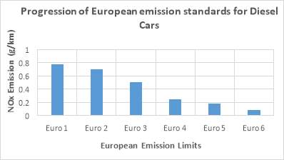
Figure 4: NOx emission limits in European emission standards [8]
Figure 5 shows the trends of reduction of Particulate Matter emissions for diesel vehicles with progressing European emission standards. It can be seen from the figure that Particulate emission limits has be reduced to 0.005g/km (Euro 6) from 0.14g/km (Euro 1). There is a major reduction of 96%. [8]
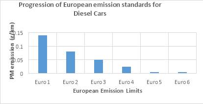
Figure 5: PM emission limits in European emission standards [8]
Figure 6 shows substantial reduction in Carbon monoxide emission limits over the years. [8]
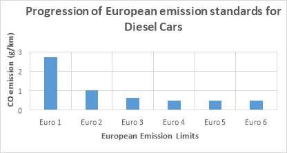
Figure 6: COemission limits in European emission standards [8]
More strict emission legislations are expected in coming future. The automakers have to come up with new technologies that can reduce the emission and can make diesel vehicles to comply with the current and future emission standards. There are two ways to decrease pollutants from the diesel exhaust, one is to avoid the formation of pollutants right in the combustion chamber and other is to treat the exhaust gases containing pollutants and make them clean and less harmful using after treatment systems. [9]
Selective Catalyst Reduction (SCR) is an effective method which can be employed to reduce NOx emission but it requires a lot of modification to the exhaust systems and its overall maintenance is expensive. Retardation of injection timing technique can also be used but it results in a lower fuel efficiency and an increase in soot and HC emissions. Exhaust Gas recirculation (EGR) is another method which is cheap and easy to implement. [10]
2.5 Objectives
The main objectives of the thesis is to
- Study the various environmental and health hazards associated with diesel pollutants
- Study, investigate and demonstrate the effects of increasing EGR rates on engine performance and emissions.
- Find efficient ways to curb down diesel exhaust emissions (NOx,soot, HC and CO)
3. Literature Review
3.1 NOx formation mechanism
NO and NO2 are collectively called NOx and are formed during diesel combustion. Their formation in the combustion chamber essentially depends on the temperature conditions, residence time and the Oxygen concentration in the combustion chamber. [2] In a diesel combustion, formation rates of NO is much higher than that of NO2. In fact, NO accounts for 95 to 98% of the total NOx. [12]
3.1.1 NOx production mechanisms
In a diesel combustion NOx can be essentially produced by three different mechanism.
- Thermal NOx
Atmospheric air can be considered as a mixture of 79% oxygen and 21% nitrogen. Thermal NOx is formed when the atmospheric nitrogen gets oxidised under high combustion temperatures of above 1900 K. High enough temperatures are required for the formation of Thermal NOx because of the triple bond that connects the N2 molecules. [12]
- Fuel NOx
Fuel nitrogen is another source of NO in diesel combustion engines. If the fuel contains a significant amount of nitrogen, oxidation of the fuel nitrogen-containing compounds adds to the total NOx formed during the combustion process. The NOx formed by this mechanism is called Fuel NOx. Although, diesel fuel contains a substantial amount of nitrogen, current levels of fuel NOx are insignificant. [2]
- Prompt NOx
The third source of NO formation during diesel combustion process is due to the reaction of atmospheric nitrogen N2 with radicals such as C, CH and CH2 derived from fuel. This reaction occurs in the early part of the combustion process and fixed species such as HCN (hydrogen cyanide), NH (nitrogen monohydride), H2CN (dihydrogen cyanide) and *CN (cyano radical) are formed. These species further gets oxidised to produce NO. The NOx produce by this mechanism is called Prompt NOx. Prompt NOx too have very low levels in the overall NOx produced during combustion. [11]
Among all three described NOx formation mechanisms, thermal NOx constitutes major part of the total NOx amount and therefore in this thesis only Thermal NOx will be considered.
3.1.2 NO formation mechanism
NO is formed in the post-flame combustion process in the high temperature regions of combustion chamber. The formation and decomposition of NO during the combustion process can be described by Zeldovich mechanism. [11]
The primary reactions during the combustion of near stoichiometric fuel-air mixture, leading to the formation NO are:
O + N2 = NO + N
(i)
N + O2 = NO + O
(ii)
N + OH = NO + H
(iii)
The initial NO formation rate can be written as:
dNOdt= 6 X 10¹⁶T0.5exp-69090TO2e0.5[N2]emolcm3 s
(1)
It can be seen from the equation (1) that NO formation largely depends on the combustion temperature and the oxygen concentration. High combustion temperatures and high oxygen concentrations gives high level of NO formation rates. Apart from this other factor that can influence the NO formation rates is residence time. [11]
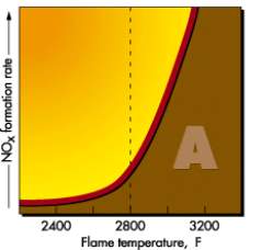
Figure 7: NOx formation rate with
Increasing Flame temperature [14]
Fig 7 shows that NOx formation is negligible until the flame temperatures reaches 2800 F (1800 K). Once that threshold temperature is passed NOx formation rates increases. [14]
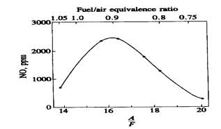
Figure 8: NO concentration with AFR
and Fuel/Air equivalence ratio [2]
Fig 8 shows the dependence of NO emissions on fuel/air equivalence ratio
3.1.3 NO2 formation mechanism
In diesel engine exhaust NO2 can be 10 to 30 percent of the total exhaust oxides of nitrogen emissions. [2] The equations governing NO2 formation during diesel combustion can be summarised as:
N + HO2 = NO2 + OH (iv)
Subsequently, the conversion of NO2 to NO takes place:
NO2 + O = NO + O2 (v)
3.2 NOx Reduction Strategies
3.2.1 Water Injection In diesel combustion
It is evident from figure 9 that water vapour has higher specific heat capacity than that of dry air. This characteristic property of water vapour can be beneficial in reducing NOx emissions from the diesel exhaust.
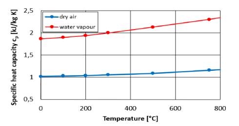
Figure 9: Specific heat capacity vs temperature
for water vapour and dry air.
Water addition to the in-cylinder charge leads to the higher specific heat capacity and thus lowers combustion temperatures. When water is added in the intake manifold (or in the cylinder for direct injection), water gets evaporated immediately and as a result an additional cooling effect occurs. The evaporation process takes heat from the intake charge and consequently, the charge air temperatures decreases, which can be seen from equation 2.
ṁw*Δhev = ṁcharge *cp* ΔTcharge
(2)
Where, ṁwis the mass of injected water (kg/s), Δhevis the enthalpy of evaporation in (J/kg), ṁchargeis the mass of intake air (kg/s), Cp is the specific heat capacity of water vapour J/(kg.K) and ΔTchargeis the reduction of intake charge temperature (K).
A lower intake charge temperature results in lower combustion temperatures.
Higher in-cylinder temperatures favours the formation of NOx during combustion and therefore the reduction in combustion temperatures because of water injection results in decrease on the production of NOx. [23]
Normally water can be added in the diesel combustion process using one of the following methods.
- Emulsified fuel, a system consisting of two immiscible liquids one dispersed in other is called and emulsion. In a “water-in-fuel” emulsion fine water droplets are dispersed in a diesel fuel phase. It has been found that “water-in-fuel’ emulsion can reduce NOx up to 50% from the diesel exhaust. The only limitation of this system is that it requires several engine modifications. Without the necessary engine modifications the NOx reduction is limited to only 10-20%. Other benefits of emulsified fuel injection include better atomization and mixing of the fuel. Better mixing throughout the diffusion flame gives reductions in PM emissions. This makes water-fuel emulsion one of the rare emission control strategy that can reduce NOx and PM emissions both at the same time.
- In-cylinder water injection, system requires a separate, independent, electronically controlled equipment for the injection of water into the combustion chamber. One advantage of this system over emulsified fuel system is that it does not requires any kind of engine modifications. NOx reduction capabilities of this system are comparable to that of emulsified system but because of the fact that water is not directly injected into the combustion flame, PM emissions reductions are quite low.
- Water injection to the intake air, is the simplest method for water addition into the combustion chamber. This technique allows very little control on parameters such as injection timing and for the very reason NOx reduction tend to be lower in the range of 10-20%. Another drawback of this strategy is that the water in the intake air sometimes does not fully evaporate and causes damages to the engine parts. [24]
However, one obvious disadvantage of such a system is that it would require large quantities of water for NOx reduction. This can prove to be problematic for road vehicles as they will need to have an extra equipment just to carry a larger amount of water. [24]
3.2.2 Selective Catalyst reduction
SCR is an efficient and cost effective after treatment system used to reduce NOx emissions from the diesel exhaust. The technology consist of three main component: Diesel exhaust fluid (DEF) which is a solution of 32.5% Urea and purified water, hot exhaust and catalytic convertor. DEF is used as a redundant source which hydrolyses rapidly to produce oxidizing ammonia in the exhaust stream.
SCR provides an oxidising atmosphere which permits the NOx reduction reactions to take place in its catalyst system. It is called “Selective” as it uses ammonia as a reductant to reduce NOx levels. Ammonia acts a reducing agent and reacts with NOx in the catalytic chamber to convert the pollutant into natural and less harmful elements such as nitrogen, water and small amounts of Carbon dioxide. [15]
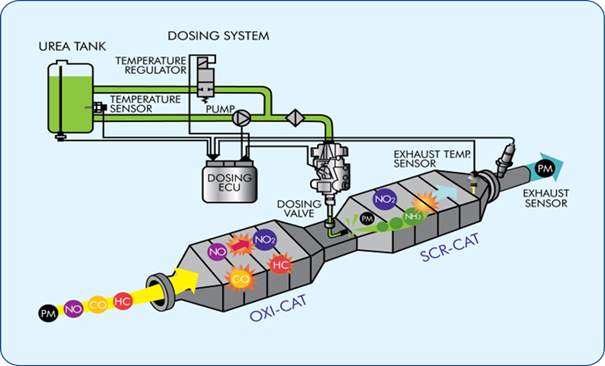
Figure 10: The working mechanism of SCR [16]
There are two different forms of ammonia which exist and can be used in SCR systems. Pure anhydrous ammonia, which is considered toxic and requires special thick shell, pressurised storage vessels and piping due to its high vapour pressure. On the other hand there is aqueous ammonia NH3.H2O which is less hazardous and easier to handle. Typically pure anhydrous ammonia is used as reductant in SCR systems. [17]
A number of chemical reaction occurs in the catalytic convertor of SCR systems and are described below:
6NO + 4NH3 = 5N2 + 6H2O
(vi)
4NO + 4NH3 + O2 = 4N2 + 6H2O
(vii)
6NO2 + 8NH3 = 7N2 + 12H2O
(viii)
2NO2 + 4NH3 + O2 = 3N2 + 6H2O
(ix)
NO + NO2 + 2NH3 = 2N2 + 3H2O
(x)
Equation vii is the most dominant and major reaction which takes place in SCR system as NOx is mostly NO (>90%). [17]
SCR process requires an accurate ammonia injection rate as low ammonia injection rates can result in low NOx conversion while on the other hand high amount of ammonia in the system can easily slip into the atmosphere. This kind of release of ammonia into the environment is called ammonia slip and due the toxic nature of ammonia, can cause several environmental and health problems.
It has been found and is clearly visible the fig 11 that ammonia slip rate is a function of NH3/NOx ratios. At ratios higher than stoichiometric ratio i.e. 1, the ammonia slip rate increases and that is why ratios between 0.9 and 1 are commonly used to minimise ammonia slippage. [17]
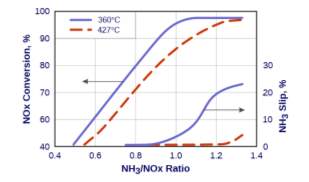
Figure 11: Dependency of NOx conversion rate
And ammonia slip on NH3/NOx ratios [17]
It is also evident from the figure that ammonia slip decreases with increase in temperatures. [17]
3.2.3 Exhaust Gas Recirculation System
Exhaust gas recirculation system is a technology that can significantly reduce NOx emissions from the diesel exhaust. While NOx reduction from the engine exhaust is the most common application of EGR in the diesel engines, it has been found that EGR has many other applications such as: improving knock resistance and reducing the need for high load fuel enrichment in SI (Spark ignition) engines. It helps in the vaporization of fuel in the SI engines and improves ignition quality of fuel in diesel engines. In 1950s, first engine experiment was conducted to investigate the NOx reduction potential of EGR, by the end of 1978 EGR became a very promising NOx reduction technology and very common strategy for NOx reduction among gasoline operated engines. Following the success of EGR in gasoline operated vehicles EGR was also introduced in diesel passenger cars, light-duty trucks and then in heavy duty diesel engines. Early in 2000s, cooled EGR became very common in heavy duty diesel engines as it was able overcome many technical challenges faced by heavy-duty-vehicles at that point of time. By the end of year 2010 EGR became very common in SI as well as CI engine, not just because of its NOx reduction capabilities but also because it could decrease pumping losses, improve combustion efficiency and enhance knock tolerance. EGR also increased exhaust gas temperatures which assisted the regeneration of DPF (diesel particulate filters). [18]
We have already established in section 2.1.2 that the NOx formation in the diesel engines is mainly a function of combustion temperature and Oxygen concentration. As the combustion temperature and Oxygen concentration inside the combustion chamber increases the NOx formation rate also increase. Exhaust Gas Recirculation system is one of the most effective way to reduce NOx emission from the diesel exhaust as it reduces the combustion temperatures and oxygen concentrations inside the combustion chamber. [19]
An EGR system most commonly consist of the following components:
- EGR control valves, device which controls the amount of exhaust gases directed back into the combustion chamber
- EGR coolers, heat exchanger devices that used coolant to reduce the exhaust gas temperatures before directing them back into the combustion chamber
- Piping [18]
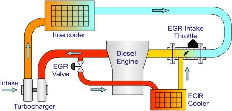
Figure 12: Exhaust Gas Recirculation System [18]
Fig is a layout of a high pressure loop, cooled EGR system which has been used in AUDI 3.3 L V8 TDI engine. In an EGR system a portion of spent exhaust gas is redirected into the combustion chamber. The gas passes through EGR control valve and then proceeds to the EGR cooler. It is imperative to cool down the exhaust gases prior to recirculation to prevent temperature rise in the combustion chamber. Subsequently, the cooled exhaust gases passes through the EGR Intake throttle where they get mixed with the high pressure, cooled (to improve density) combustion air. The mixture of air and exhaust gases is then inducted into the combustion chamber through and intake manifold. [18]
The exhaust gases which are directed back into the combustion chamber mainly contains carbon dioxide, water vapour and nitrogen. These gases have higher specific heat capacity than atmospheric air. Oxygen deficient recirculated gases displaces the fresh air entering the combustion chamber and reduces the oxygen content available for combustion. This in turn lowers the effective AFR and affects the exhaust emissions significantly. The exhaust gas-atmospheric air mixture increases the specific heat of the intake mixture and results in the significant reduction of flame temperature. Therefore, lower oxygen content in the intake mixture and reduced flame temperatures together results in the reduced NOx formation rates. [19]
The effects of exhaust gas addition to the intake air in a diesel combustion can be summarised below:
- Heat capacity of the intake charge increases which results in lower flame temperatures
- The exhaust gas dilutes the intake charge and makes it oxygen deficient
- The exhaust gas addition leads to an increase in inlet temperatures
- EGR addition causes changes in the flame structure which alters combustion duration or increases the ignition delay time
- Inlet concentration of pollutants increases due to the recirculation. [20]
It has been found that the thermal EGR mechanism plays a more dominant role in flame temperature reduction and hence a decrease in NOx emission from diesel exhaust.

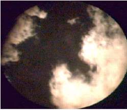
Figure 13: Bright regions bordering the darker regions containing air. [37]
Figure 13 shows the burning environment in the combustion chamber of a heavy duty diesel engine (Image obtained at 1200 RPM – 30% Load). The bright flame region can be seen naturally bordering the black region which mostly consist of oxygen and nitrogen. [37]
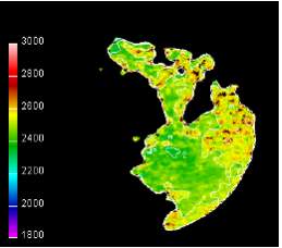
Figure 14: Flame temperature contours [37]
Figure 14 show that the hottest spots are found at the boundary of the flame region, in contact with the unburned charge having highest concentrations of nitrogen and oxygen and thus resulting in high NOx formation rates.
Sets of flame temperature contours are illustrated in the figure 15 showing the reliance of flame temperatures on EGR rate. Four sets of each containing five images are shown in the figure corresponding to the application of no EGR and 10%, 20% and 35% EGR. A significant decrease in the flame temperature with increasing EGR rates is clearly visible in the figure.
Evidently, it can be established that a thermal EGR mechanism play a more dominant role in flame temperature reductions. Residual exhaust gases contains increased concentrations of CO2 and water which have higher specific heat capacities at normal combustion temperatures. More energy is required to pre heat these molecules by flame in order to make them attain the same temperatures as that of flame front. This results is the decrease of flame temperatures. [37]
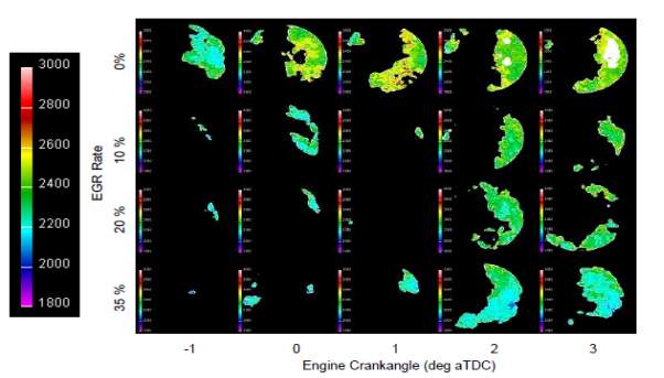
Figure 15: Flame temperature images illustrating the decrease in flame temperatures with increasing EGR rate.
3.3 Analysis and Interpretation of an EGR flow system
EGR (%) and EGR rate
The mass percent of recirculated gas in the total intake mixture is termed as EGR (%).
EGR (%) = ṀrecṀrec + Ṁair X 100
(3)
Where
Ṁis mass flow rate in
(kg/hr)
Ṁrec
is the mass flow rate of exhaust in
(kg/hr)
Ṁair
is the mass flow rate of air in
(kg/hr)[20]
In terms of CO2 measurements at the intake and the exhaust manifold the EGR rate can be defines as: [19]
EGR = CO2intake-CO2atmCO2exhaust-CO2atm
(4)
Below, the effects of EGR on the exhaust emissions are described in detail using an EGR flow system (Figure 16).
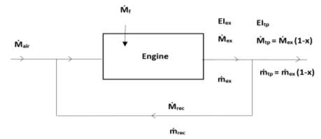
Figure 16: A basic layout of an EGR system [20]
In the above shown flow system
Ṁand
ṁrespectively can be defined as the mass flow rate of all gases and of each pollutant measured in kg/hr. The subscripts used are: air for inlet air, f for fuel, ex for exhaust gases, rec for recirculated exhaust gases and tp for tailpipe.
Before investigating the effects of EGR on the diesel combustion it is imperative to define an EI (Emission Index) for the recirculated exhaust gases. EI is defined as grams of pollutants per kilogram of fuel.
On applying the equation 3 to the above shown flow system, expression for recirculated gases can be written as:
Ṁrec = x Ṁex = x (Ṁair + Ṁrec+ Ṁf) (kg/hr)
(4)
Where
Ṁexis the mass flow rate of exhaust in
(kg/hr), Ṁrecis the mass flow rate of recirculated exhaust
(kg/hr),
Ṁairis the mass flow rate of air
(kg/hr)and
Ṁfis the mass flow rate of fuel measured in
kg/hr.
x
is defined as the mass fraction of exhaust gas recirculated.
Likewise, we can derive the expression for the amount of exhaust leaving the tailpipe
Ṁtp, which is:
Ṁtp = Ṁex (1-x) (kg/hr)
(5)
The measured tailpipe emission values can be further written in terms of
EI (g/kg)using the expression
EItp = ṁtpṀf = ṁex(1-x)Ṁf (gkg)(6)
Where,
EItpis the emission index of pollutant at the tailpipe
(g/kg),
ṁtpis the mass flow rate of the pollutant at the tailpipe
(g/kg)and
ṁexis the mass flow rate of the pollutant at the engine exhaust
(g/kg).
Above equation gives an expression for tailpipe emissions but it fails to describe the actual mass of pollutant per mass of fuel being generated by the combustion process in the combustion chamber. This can be evaluated using the expression:
EIex =ṁexṀf(gkg)
(7)
On substitution with equation 6, the equation 7 can also be written as
EIex = EItp(1-x)(gkg) (8)
To derive the above equation it has been assumed that all the pollutants present in the recirculated exhaust are destroyed in the combustion process. The equation to evaluate the
EIexwhen the recirculated pollutant is not destroyed is: [20]
EIex = ṁexṀf- ṁrecṀf
(9)
Chemical equation governing the diesel combustion when there is no dilution can be written as:
C14.4H24.9+ast+ aexO2+3.76N →yields 14.4CO2 +12.45H2O+3.76ast+ aexN2
+ aexO2 (10)
Where,
ast
=
20.625 molesof air required for stoichiometric combustion of 1 mol of fuel.
aex
=
ast (
1-φφ)
φ
= equivalence ratio,
and
xis the EGR flow rate [10]
When the exhaust-air mixture is added to the intake charge a complex feedback-like process takes place. CO2, H2O and concentrations of other pollutants converge like a geometric sequence of steady-state concentrations.
Moles of CO2 / mol of fuel =
14.4 (x + x2 + x3+ ….)
= (14.4 x1-x)
Moles of H2O / mol of fuel =
12.45 (x + x2 + x 3+ ….)
= (
12.45 x1-x)
The chemical equation of diesel combustion on addition of EGR:
C14.4H24.9+aO2+3.76N+x[(14.4 x1-x) CO2 +
(
12.45 x1-x)
H2O + bN2 +
c CO2 ] →yields (14.4 x1-x) CO2 + (
12.45 x1-x)
H2O + bN2
+ c CO2 (11)
3.4 The Soot-NOx trade off
When on one side use of EGR can be instrumental in reducing NOx emissions from diesel exhaust, it can also prove to be obstructive as it leads to the increase in the production of soot particles. With the use of EGR there is always a trade-off between reduction in NOx and increase in soot, CO and unburned HC. EGR also results in higher specific fuel consumption. The rate of soot oxidation/re-burning is greatly reduced due to the lower flame temperatures and therefore, more soot is produced during the combustion. The soot remains un-oxidised due to oxygen deficient environment and appears eventually in the diesel exhaust. This leads to the rise in smoke level of engine exhaust and affects the performance of engine in many ways. The higher smoke levels increases the carbon deposits and leads to the wear of various vital engine parts such as valve train, piston rings, cylinder liners and bearings. EGR application also reduces the engine durability and the quality of the lubricating oil. Lubricating oil thickens when it get mixed with the soot particles and therefore the wear debris in the oil increases. [21]
It has been found that there is a significant increase in soot particles when more 50 % EGR is used. Therefore, use of a particulate trap along with EGR system has been recommended to trap smoke particles, un-burned HC and NOx simultaneously. [22]
4. Methodology
For this thesis, the experimental emission data was collected at University of Southampton’s Bolderwood campus from the UNI-LINK City bus running in Southampton city on a light-duty Cummins B series diesel CI engine rated for 1000 Nm (740 ft-lbs) torque at 1200-1600 RPM, and 247HP at 2100 RPM. [28] [30] Uni-Link city bus has been running in Southampton City since 2001 and is been used since then by university staff and students to commute between teaching sites and halls of residence. The Uni-Link’s current fleet running in Southampton consist of 23 double decker buses manufactured by Scottish bus Manufacturer called Alexander Dennis. [25] [26]
4.1 Bus and Engine specifications
The current Uni-Link fleet running in Southampton city uses the all new Alexander Dennis’s Enviro 400 double decker buses (Fig 17).
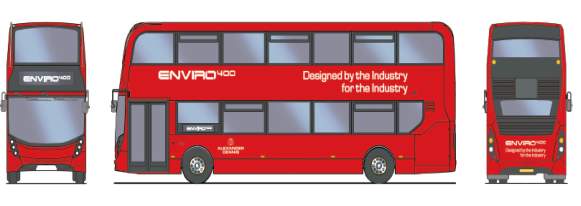
Figure 17: Alexander Dennis’s Enviro 400 [27]
These buses are packed with latest Cummins ISB6.7 (Interact System B) 6 cylinder turbocharged and intercooled diesel engine. The engine is also certified to the EURO 6 emission standards.
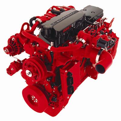
Figure 18: ISB 6.7L Cummins Engine [29]
Additionally, buses are also equipped with latest emission control technologies such as EGR,
VGT (Variable Geometry Turbo), SCR, and DPF. [27]
| Engine Specifications [28] [30] | Value | ||
| Model | 6.7L ISB Cummins | ||
| Type | Inline Six cylinder turbo, Direct fuel injection | ||
| Displacement | 408 cu in | ||
| Bore | 107.0 mm | ||
| Stroke | 124.0 mm | ||
| Compression Ratio | 17.3 : 1 | ||
| Max Power | 246.58 HP @ 2100 RPM | ||
| Max Torque | 1000 Nm or 740 ft-lbs @ 1200-1600 RPM | ||
| Cylinders | 6 inline | ||
| Weight | 1050-1150 lbs dry | ||
| Engine Management | Bosch | ||
| Fuel Injection | High Pressure diesel direct injection with 7 direct hole injectors, 26,000 psi maximum injection pressure. | ||
| Dimensions | Length | Breadth | Height |
| 41.7” | 28.6” | 37.8” | |
Table 2: Engine Specifications
4.2 Study and Analysis
The bus was test ran by Southampton City Council at University’s Bolderwood Campus on 15th of September 2015 for a total time of 8 minutes. The engine tests were conducted at maximum 30 RPM (8.8 m/s velocity), mid load to replicate the city driving conditions. The engine was equipped with an EGR system and was operated at 10% EGR rate. Engine performance and emission data corresponding to different velocities was collected using different sensors, analysers and technologies, and were stored in a form of an excel document.
Several variables were measured during the tests, such as velocity, ambient humidity, ambient temperature, ambient pressure, Exhaust temperature (EGTS), Exhaust Flow , air flow (Oxygen sensor), fuel flow, Power and Air-fuel ratio (AFR sensor). Exhaust gas analysers were used to record exhaust emission data. NDIR analyser was used to measure CO/CO2 emissions, NO and NOx concentrations were measured using chemiluminescence analyser and HC emissions using Hot FID analysers. [40]
A separate document was then created containing averaged values of emission and engine performance data corresponding to the each velocity terms. Several other important variables such as RPM, Horsepower and bsfc were then evaluated using the recorded data. Subsequently, to better understand the engine running conditions several plots were made using the initial and the evaluated data. These plots included; Engine performance curve, bsfc vs rpm, CO vs rpm, NOx vs rpm, HC vs rpm and EGT vs rpm (as a function of 10% EGR).
The second part of the study included the analysis and the estimation of the pollutant emissions and engine performance parameters with increasing EGR rates. The following equations (already mentioned in section 2.3) were used in analysis of collected data.
EIex= EItp(1-x) (gkg)
(8)
EIex= ṁexṀf- ṁrecṀf (gkg)
(9)
Volumetric Efficiency, Brake thermal efficiency, NOx, CO and HC emissions were then estimated as a function of increasing EGR (15, 25, 35, 45 and 50%) using above two equations from the collected data.
Equation 8 was used to estimate the HC and CO emissions while NOx emissions, with increasing EGR were estimated using equation 9.
5. Results and Discussion
5.1 Engine Performance and Emission Analysis on EGR usage
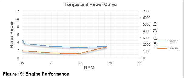
Figure 19 is an Engine performance curve which shows the variations of torque and power with increasing RPM values. The engine speed (revolutions per minute) ranging from 15 to 30 RPM is depicted on the horizontal axis, while Horsepower ranging from 0 to 6HP and torque ranging from 0 to 7000 ft-lb is shown on each of the two (Primary and secondary respectively) vertical axes. [31]
Torque is the ability of engine to do a certain work or it is the amount of twisting force that a piston applies on the crankshaft. Power, on the other hand is the rate at which the work is done over a certain period of time. Power is essentially torque x speed and can be written as a function of torque using the expression:
Horsepower
=
Torque lb-ft X RPM5252 [32]
(12)
For a CI engine as the RPM value increases the engine torque also increases and attains a peak value at a certain RPM. This peak occurs quite early in the performance curve at low RPM values. With further increase in the RPM, the torque decreases. This torque decrease is due the incapability of engine to fully pack itself with air at higher RPM values.
As it has already been mentioned that power is a function of torque therefore the shape of the torque curve greatly influence the shape of the power curve. The power curve peak always occurs later than that of torque curve. At much higher RPM values frictional losses becomes significant and power starts to drop.
In the graph shown above, the Power – Torque vs RPM trend which has be described is not completely visible as this is based on the data collected from the city bus which was test run at very low RPM values. However, a sudden increase in the torque value at low RPM is clearly visible in the curve. While on the other hand there is a gradual increase in Power with the increasing RPM values. This make sense as a bus needs higher torque at low RPM values to carry the weight of the Passengers. [31] [32]
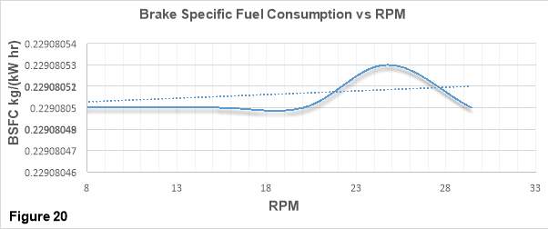
Figure 20 shows the trends of BSFC (Brake Specific Fuel Consumption) in kg/(kW hr) with increasing RPM values.
BSFC is the measure of how efficiently a given amount of fuel is converted into a specific amount of Power. [2]
bsfc= ṁfP
[2]
(13)
The plot is generated using the data collected from the city bus which was test run at lower RPM values. In a typical bsfc vs RPM curve, bsfc values are found to be considerably high at lower and higher RPM values. While, at the middle revs bsfc values are found to be lowest (desirable). Bsfc is low at lower RPMs because it has been found that “there is an increased time for the heat of combustion to escape through the walls of the cylinders and so not do useful work.” At Higher engine speeds the bsfc is low due to the significant increase of friction losses which results in higher fuel consumption. These losses leads to the wastage of a substantial amount of combustion energy.
The trend line in the Figure 20 shows a steady increase in the bsfc values with the increase in speed. From the trend we can predict that it is very likely for the curve to follow the same trend which has been described above.
The engine from which the data was collected for this plot is equipped with EGR technology and uses a 10% EGR rate. Application of EGR reduces the discharge air and makes the intake charge oxygen deficient. This affects the AFR as less oxygen is available for the combustion process. As bsfc is a function of AFR, the AFR change results in bsfc increase. This bsfc increment is clearly visible in the plot and can be improved by introducing pressurised inlet air into the combustion chamber. This would increase the density of the air and hence more oxygen would be available for the combustion. [31]
Figure 21 shows the variations of NOx emissions in PPM (Part per Million) with increasing RPM when the engine runs at 10% EGR rate. NOx emissions ranging from 1 to 2.6 PPM are chartered on vertical axis while RPM values ranging from 0.5 to 30 rpm are chartered on the horizontal axis.
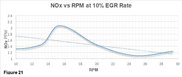
In a typical NOx vs rpm curve, there is an initial increase in the NOx emissions, the emissions peaks at mid revs and then with further increase in speed the NOx emissions declines. The main reason that the NOx follows this trend is because of its dependance on the engine load. As the engine load increases, the temperature in the combustion chamber increases which leads to a significant increase in the NOx emissions. At higher rpm values (low engine load), the residence time of the gases in the combustion chamber is short therefore not much of oxygen is available for nitrogen to react with and hence NOx emission declines.
A simililar trend can be see in figure 3. It shows that NOx emissions decraeses with the increase in the rpm. [33]
Application of EGR might be another factor responsible for giving such a trend in figure 3. It has already been mentioned in the thesis that NOx is a direct function of combustion temperature and oxygen concentration occuring in the combustion chamber. The data which has been used to generate figure 1 is retrived from the engine that uses EGR technology and runs at 10% EGR rate. EGR is found to reduce the oxygen concentration of the intake charge and hence combustion temepratures by redirecting a portion of spent exhaust gas into the combustion chamber. The lower combustion temperatures are unfavourable for the NOx production and therefore NOx emissions declines. This is can be clearly seen in the plot.
Figure 22 shows the variations of CO emissions with increasing RPM for the engine running at max 30 rpm. CO emissions in percentage Volume are depicted on the vertical axis while RPM values ranging from 0 to 30 rpm is depicted on horizontal axis.
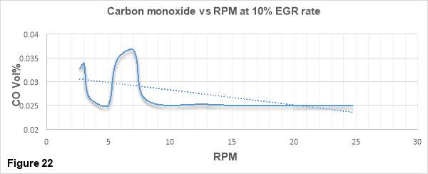
Carbon monoxide is formed when there not enough oxygen present in combustion chamber. In figure 22 a clear trend is visible in which CO emissions are decreasing with the increase in engine speed. This is because when the engine speed increases, the fuel injector system injects more fuel into the combustion chamber. Because of this, the air-fuel mixing process becomes more intensive and higher fuel/air equivalence ratios are achieved. This augments the conversion of CO into CO2 and as a result the CO emissions are decreased. [34]
Figure 23 shows the variations THC (Total Hydrocarbons) with increasing engine speeds (rpm) for the engine running at maximum 30 rpm. THC concentration in ppmC is depicted on the vertical axis while the horizontal axis contains the rpm values.
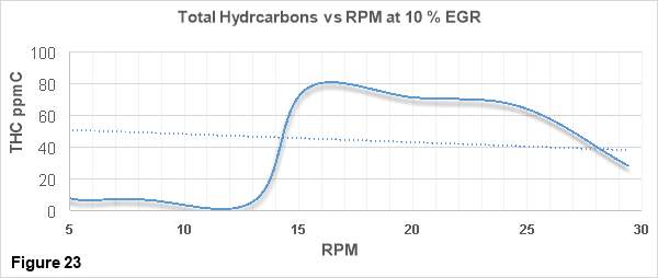
From the figure 23, a clear decrease of THC emissions with increasing engine speeds is visible. As stated above in the thesis, as the engine speed increases, more fuel is injected into the combustion chamber which improves the air-fuel mixing and a higher fuel/air equivalence ratios are achieved. It has already been mentioned that THCs are the products of incomplete combustion. Better air-fuel mixing improves the quality of combustion and reduces the production of the products of incomplete combustion such as THC. [34]
Figure 24 depicts the variations of exhaust gas temperature with increasing rpm values for the engine which was run at maximum speed of 30 rpm. EGT in degree Celsius is chartered on vertical axis while horizontal axis contains rpm values ranging from 5 to 30 rpm.
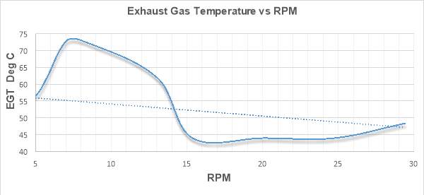
Figure 24
From the figure it can be seen that Exhaust gas temperature decreases as the engine speed increases. This trend might be due the incapability of the engine to ingest more air at high rpms. At higher rpms, engine’s capability to pack itself with air declines and the residence time of gases drops. This leads to the lower oxygen availability in the combustion chamber and hence the combustion temperatures and EGT drops. [33]
Application of EGR mechanism to the engine is another reason for getting this kind of trend. EGR has high specific heat capacity. When the recirculated exhaust gases are mixed with the intake charge, the oxygen availability in the combustion chamber drops. Therefore, the oxygen deficient nature and the high specific heat capacity of the intake charge makes the in cylinder temperatures and EGT to drop down. [35]
Figure 25 depicts the variation of NOx emission index with increasing velocity at different EGR rates. EGR rates of 15, 25, 35, 45 and 50% has been used to study the effects of EGR system on the diesel combustion in this thesis. EINOx in g/kg is represented on the vertical axis while velocity ranging from 1 to 10 m/s is depicted on the horizontal axis.
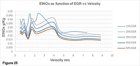
A drastic reduction of NOx emission with increasing EGR rate is clearly visible in figure 7. Considering a velocity of 8 m/s, NOx emission has decreased by 33% from 0.02 g/kg at 25% EGR rate to 0.014 g/kg at 50% EGR rate.
As discussed in earlier sections, the NOx formation mechanism is a function of flame temperature and oxygen concentration. The diesel combustion provides both of these vital conditions. The thermal EGR mechanism has already been investigated in section X, therefore it is clear that thermal EGR mechanism plays a dominant role in the flame temperature reduction and hence NOx emission reduction with increasing EGR rates. The recirculated exhaust contains high concentrations of carbon dioxide and water. As the EGR rate increase the concertation of CO2 and water also increases. Both of these molecules have heat capacities higher than that of atmospheric air at typical combustion temperatures due to which more energy is required to pre-heat the incoming mixture which in turn reduces the flame temperature.
Besides this, lower oxygen and nitrogen concentrations can also influence the NOx formation rates. As the EGR rates increase the oxygen and nitrogen concentrations in the intake charge drops and the probability of oxygen and fuel molecules to meet decreases.
Lower flame temperatures and oxygen-nitrogen concentrations are unfavourable for the NOx formation mechanism and hence NOx emissions declines. [37
Figure 26 shows the variations of THC emission index as a function of EGR rate with increasing velocity. EITHC in g/kg is plotted on the vertical axis against the velocity ranging from 0 to 20 m/s which has been depicted on the horizontal axis.
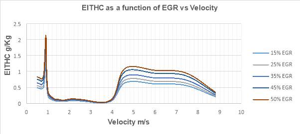
Figure 26
From figure 26 it is clear that THC emissions increases significantly with the increase in EGR rate. The graph shows a 12% increase (from 0.31 g/kg at 15% EGR rate to 0.34 g/kg at 50% EGR rate) in the THC emission at the maximum velocity of 8.8 m/s. Normally, HCs are the outcome of incomplete combustion and are formed in the low combustion temperature regions of the combustion chamber such as boundary layers near the cylinder walls. Application of EGR mechanism and the increasing EGR rates reduces the flame temperature and the overall oxygen concertation in the combustion chamber. Consequently, a rich air-fuel mixture is formed at different locations in the combustion chamber. Lower oxygen availability for the combustion process results in the incomplete combustion, leading to a significant rise in HC production. [21] [38]
In figure 27, CO emission index as function of EGR rates is plotted against the velocity. The horizontal axis represents EICO in g/kg while the vertical axis contains velocity ranging from 0 to 10 m/s.
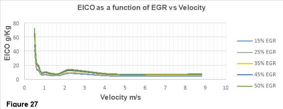
From the graph it is clear that CO emission increases with the increase in EGR rates. Higher EGR rates decrease the oxygen concentrations in the combustion chamber. Therefore, Oxygen deficiency in the combustion chamber can attributed to the increase in CO emissions as there is not oxygen left to react with carbon and form CO2. [38]
Figure 28 shows the trend of volumetric efficiency with increasing EGR rates. Vertical axis shows the volumetric efficiency while different EGR rates are depicted on the horizontal axis.
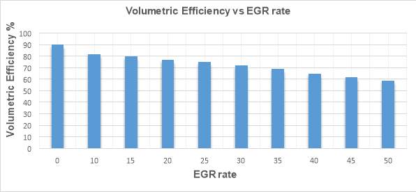
Figure 28
The ratio of the actual amount of air that the engine ingest to the theoretical maximum is called VE (Volumetric efficiency). [39]
It can be seen in the figure 28 that as the EGR rate increases the volumetric efficiency decreases. EGR application in a diesel engine reduces the intake air mass flow and a result VE drops.
Figure 29 shows the variations of Thermal efficiency with increasing EGR rate. Thermal efficiency has been depicted on the vertical axis while different rates are shown the horizontal axis.
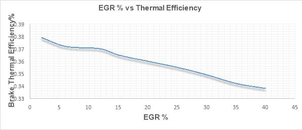
Figure 29
Typically, there is an initial increase in BTE (Brake Thermal Efficiency) with EGR but as the EGR rate increases BTE drops. The reason for this initial increase in BTE is the re-burning of HC entering the combustion chamber. However, Figure 29 shows an overall decrease in BTE as a function of EGR. Clearly, the BTE drop is significant one and is due to two main reasons; decreased combustion work (indicated work) and increased pumping work. Application of EGR in an engine leads to the combustion deterioration, it reduces the combustion temperatures and affects the air-fuel ratio. EGR reduces the oxygen concentration in the combustion chamber and hence directly affect the AFR. Therefore, excessive recirculation of exhaust gases in the combustion chamber reduces the BTE.
Additionally, increased pumping losses also leads to the BTE degradation. The pumping work is due the VGT that engine uses to increase the exhaust manifold pressure, to force a portion of exhaust gas back into the combustion chamber.
6. Conclusions and Recommendations
The study examined the various effects of EGR application on engine performance and pollutant emissions.
- Extensive study of several NOx reduction strategies (Water injection, SCR, EGR) has been conducted and it can be concluded that EGR system is the most efficient way to reduce NOx emission from the diesel exhaust.
- The NOx-Soot trade off can be dealt by coupling the EGR system with DPF, which can simultaneously reduce the NOx and Soot emissions.
- It was also established in the thesis that the EGR thermal mechanism plays a more dominant role in flame temperature reduction inside the combustion chamber and hence NOx emissions with increasing EGR rates. Significant reductions in NOx emissions were observed with increasing EGR rates and thus EGR reduction can be correlated with flame temperature effects.
7. References:
[1]Dieselnet.com. (2017). Combustion in Diesel Engines. [online] Available at: https://www.dieselnet.com/tech/diesel_combustion.php [Accessed 26 Mar. 2017].
[2] Heywood, J. (n.d.). Internal combustion engine fundamentals.
[3] Reşitoğlu, İ., Altinişik, K. and Keskin, A. (2014). The pollutant emissions from diesel-engine vehicles and exhaust aftertreatment systems. Clean Technologies and Environmental Policy, 17(1), pp.15-27.
[4] Diffen.com. (2017). Diesel vs Petrol – Difference and Comparison | Diffen. [online] Available at: http://www.diffen.com/difference/Diesel_vs_Petrol [Accessed 28 Mar. 2017].
[5] Fiebig, M., Wiartalla, A., Holderbaum, B. and Kiesow, S. (2014). Particulate emissions from diesel engines: correlation between engine technology and emissions. Journal of Occupational Medicine and Toxicology, 9(1), p.6.
[6] Epa.gov. (2017). Particulate Matter (PM) Pollution | US EPA. [online] Available at: https://www.epa.gov/pm-pollution [Accessed 28 Mar. 2017].
[7] Rac.co.uk. (2017). Euro 1 to Euro 6 – find out your vehicle’s emissions standard | RAC Drive. [online] Available at: http://www.rac.co.uk/drive/advice/know-how/euro-emissions-standards/ [Accessed 28 Mar. 2017].
[8] Anon, (2017). [online] Available at: https://www.theaa.com/driving-advice/fuels-environment/euro-emissions-standards [Accessed 29 Mar. 2017].
[9] Reifarth, S. and Angstrom, H. (2010). Transient EGR in a High-Speed DI Diesel Engine for a set of different EGR-routings. SAE International Journal of Engines, 3(1), pp.1071-1078.
[10] Krishnan, A. and C. Sekar, V. (2006). Prediction of NOx reduction with Exhaust Gas Recirculation using the Flame Temperature Correlation Technique. p.1.
[11] Sciencedirect.com. (2017). Effect of Exhaust Gas Recirculation (EGR) on Performance and Emission characteristics of a Three Cylinder Direct Injection Compression Ignition Engine. [online] Available at: http://www.sciencedirect.com/science/article/pii/S1110016812000907 [Accessed 31 Mar. 2017].
[12] DIOTALLEVI, F. (2007). Development of a Multi-Zone Model for NO x Formation in Diesel Engines.
[13] Pinterest. (2017). Diesel Engines. [online] Available at: https://uk.pinterest.com/aronsirjan/diesel-engines/ [Accessed 31 Mar. 2017].
[14] Alentecinc.com. (2017). The formation of NOx. [online] Available at: http://www.alentecinc.com/papers/NOx/The%20formation%20of%20NOx_files/The%20formation%20of%20NOx.htm [Accessed 1 Apr. 2017].
[15] Factsaboutscr.com. (2017). What is SCR? | Facts About SCR. [online] Available at: http://www.factsaboutscr.com/scr/ [Accessed 1 Apr. 2017].
[16] Natso.com. (2017). What Is The Difference Between Exhaust Gas Recirculation And Selective Catalytic Reduction? – NATSO Blog – NATSO. [online] Available at: https://www.natso.com/blog/what-is-the-difference-between-exhaust-gas-recirculation-and-selective-catalytic-reduction [Accessed 1 Apr. 2017].
[17] Dieselnet.com. (2017). Selective Catalytic Reduction. [online] Available at: https://www.dieselnet.com/tech/cat_scr.php [Accessed 1 Apr. 2017].
[18] Dieselnet.com. (2017). Exhaust Gas Recirculation. [online] Available at: https://www.dieselnet.com/tech/engine_egr.php [Accessed 2 Apr. 2017].
[19] Hussain, J., Palaniradja, K., Alagumurthi, N. and Manimaran, R. (2012). Effect of Exhaust Gas Recirculation (EGR) on Performance and Emission characteristics of a Three Cylinder Direct Injection Compression Ignition Engine. Alexandria Engineering Journal, 51(4), pp.241-247.
[20] Plee, S., Ahmad, T. and Myers, J. (1981). Flame Temperature Correlation for the Effects of Exhaust Gas Recirculation on Diesel Particulate and NO x Emissions. SAE Technical Paper Series.
[21] Agarwal, D., Singh, S. and Agarwal, A. (2011). Effect of Exhaust Gas Recirculation (EGR) on performance, emissions, deposits and durability of a constant speed compression ignition engine. Applied Energy, 88(8), pp.2900-2907.
[22] Varshney, V., Gaurav, K., Tripathy, S. and Agrawal, A. (2011). Design of an Experimental EGR System for a Two Cylinder Diesel Engine. pp.1-8.
[23] Kettner, M., Dechent, S., Hoffman, M., Huber, E., Arruga, H., Mamat, R. and Najafi, G. (2016). Investigating the influence of water injection on the emissions of a diesel engi. Journal of Mechanical Engineering and Sciences (JMES), 10(1).
[24] Dieselnet.com. (2017). Water in Diesel Combustion. [online] Available at: https://www.dieselnet.com/tech/engine_water.php [Accessed 13 Apr. 2017].
[25] Unilinkbus.co.uk. (2017). unilink bus. [online] Available at: http://www.unilinkbus.co.uk/ [Accessed 13 Apr. 2017].
[26] Osborn, S. and Osborn, S. (2017). Unilink Relaunch Marks Franchise Anniversary. [online] Wessex Scene. Available at: http://www.wessexscene.co.uk/news/2013/09/06/unilink-relaunch-marks-franchise-anniversary/ [Accessed 13 Apr. 2017].
[27] Alexander-dennis.com. (2017). Enviro400 | Alexander Dennis. [online] Available at: http://www.alexander-dennis.com/products/enviro400-euro6/ [Accessed 13 Apr. 2017].
[28] Anon, (2017). [online] Available at: http://www.ramtrucks.com/en/2011/ram_2500_3500/capability/powertrain/ [Accessed 14 Apr. 2017].
[29] Fleetowner.com. (2017). International WorkStar now available with Cummins ISB 6.7L engine. [online] Available at: http://fleetowner.com/equipment/international-workstar-now-available-cummins-isb-67l-engine [Accessed 14 Apr. 2017].
[30] Cumminshub.com. (2017). 6.7L Cummins ISB Turbodiesel Specs. [online] Available at: http://www.cumminshub.com/67.html [Accessed 14 Apr. 2017].
[31] integratedsimtech. (2017). Engine Performance Curve. [online] Available at: http://integratedsimtech.com/Engine_Performance_Curve.html [Accessed 15 Apr. 2017].
[32] Largiader.com. (2017). Torque and Power. [online] Available at: http://largiader.com/articles/torque.html [Accessed 15 Apr. 2017].
[33] Take me beyond the Horizon. (2017). How to Go Fast Faster: The Math Behind Turbocharging. Part 3b: Brake Specific Fuel Consumption (BSFC). [online] Available at: https://takemebeyondthehorizon.wordpress.com/2009/09/28/how-to-go-fast-faster-the-math-behind-turbocharging-part-3b-brake-specific-fuel-consumption-bsfc/ [Accessed 16 Apr. 2017].
[34] Benjumea, P., Agudelo, J. and Agudelo, A. (2009). Effect of altitude and palm oil biodiesel fuelling on the performance and combustion characteristics of a HSDI diesel engine. Fuel, 88(4), pp.725-731.
[35] Tesfa, B., Gu, F., Mishra, R. and Ball, A. (2014). Emission Characteristics of a CI Engine Running with a Range of Biodiesel Feedstocks. Energies, 7(1), pp.334-350.
[36] Hawi, M., Kiplimo, R. and Ndiritu, H. (2015). Effect of Exhaust Gas Recirculation on Performance and Emission Characteristics of a Diesel-Piloted Biogas Engine. Smart Grid and Renewable Energy, 06(04), pp.49-58.
[37] Jacobs, T., Assanis, D. and Filipi, Z. (2003). The Impact of Exhaust Gas Recirculation on Performance and Emissions of a Heavy-Duty Diesel Engine. The university of Michigan, pp.1-13.
[38] Mr. Harshraj Dangar, M. (2013). Combine Effect of Exhaust Gas Recirculation (EGR) and Varying Inlet Air Pressure on Performance and Emission of Diesel Engine. IOSR Journal of Mechanical and Civil Engineering, 6(5), pp.26-33.
[39] Inc., J. (2017). Volumetric Efficiency (and the REAL factor: MASS AIRFLOW), by EPI Inc.. [online] Epi-eng.com. Available at: http://www.epi-eng.com/piston_engine_technology/volumetric_efficiency.htm [Accessed 17 Apr. 2017].
[40] E-inst.com. (2017). Emissions Analyzers, Portable Emissions Analysers & Monitoring for Industrial Applications | E Instruments | www.e-inst.com. [online] Available at: http://www.e-inst.com/industrial-gas-analyzers/ [Accessed 18 Apr. 2017].
Cite This Work
To export a reference to this article please select a referencing stye below:
Related Services
View all


Related Content
All TagsContent relating to: "Energy"
Energy regards the power derived from a fuel source such as electricity or gas that can do work such as provide light or heat. Energy sources can be non-renewable such as fossil fuels or nuclear, or renewable such as solar, wind, hydro or geothermal. Renewable energies are also known as green energy with reference to the environmental benefits they provide.
Related Articles
DMCA / Removal Request
If you are the original writer of this dissertation and no longer wish to have your work published on the UKDiss.com website then please: