Development of Flapping Wings of Bird
Info: 13581 words (54 pages) Dissertation
Published: 10th Dec 2019
Tagged: Animal Sciences
ABSTRACT
This project is aimed to develop a wing mechanism for a wave Wing Vehicle, while not considering the aeromechanics of the wings within the style. This blood vessel bird are going to be the scale of roughly 60cm. There for the mechanics phenomena in wave flight area unit studied and summarized. It covers the leading edge vortex (LEV), wing wake interactions and the clap-and- fling result, motion carry. This is often followed by a review of natural flappers. The kinematic pattern and mechanics of bats, hummingbirds, insects and in y bird’s area unit summarized. Supported this review many completely different ideas of mechanisms for wave wings area unit generated, that area unit separated for the wave motion and also the pitching motion. Employing a qualitative analysis, the standard of the ideas area unit determined in line with completely different criteria akin to weight, size, robustness, mechanical quality, predictable power accuracy consumption and consumption. All through the look method the main focus is about additional on obtaining a strong and easy mechanism that might be used as a take a look at bench for more investigations and measurements. Concluding, the mechanism is factory-made and assembled to prove the feasibleness.
TABLE OF CONTENTS
LIST OF FIGURES
Sl.No. Name of figure Page No.
| ABSTRACT | I | |
| LIST OF FIGURES | II | |
| Page No. | ||
| CHAPTER-1 | INTRODUCTION | 1 |
| CHAPTER-2 | LITERATURE REVIEW | |
| 2.1 UNIVERSITY OF TORONTO MODEL | 6 | |
| 2.2 DELFLY | 8 | |
| 2.3 HARVARD UNIVERSITY OF ROBOBEE | 10 | |
| 2.4 WING DESIGN | 12 | |
| 2.6 MECHANISM | 15 | |
| 2.7 GEARS AND GEAR TRAINS | 17 | |
| 2.8 LINKAGES | 23 | |
| 2.9 D.C.MOTOR | 27 | |
| 2.10 ARC WELDING | 34 | |
| CHAPTER-3 | DESIGN AND SELECTION OF PARTS | |
| 3.1 BODY | 38 | |
| 3.2 WINGS | 39 | |
| 3.3 HINGE | 40 | |
| 3.4 DRIVE TRAIN | 40 | |
| 3.5 BATTERY | 43 | |
| 3.6 MOTOR | 44 | |
| CHAPTER-4 | MANUFACTURING OF PARTS | |
| 4.1 WING SPARS | 46 | |
| 4.2 BODY | 47 | |
| 4.3 ARC WELDING | 47 | |
| 4.4 FINAL ASSEMBLY | 47 | |
| CHAPTER-5 | CONCLUSIONS | 49 |
| BIBLIOGRAPHY 50 | ||
- Figure 1.1 AIR LOAD 2
- Figure 1.2 LILIENTHAL MODEL 3
- Figure 1.3 QUILL STRUCTURE 4
- Figure 2.1 TORONTO MENTOR PROJECT 6
- Figure 2.2 DELFLY 8
- Figure 2.3 DELFLY DRIVE TRAIN 9
- Figure 2.4 CLAP AND FLING 11
- Figure 2.5 HARRIS MODEL 15
- Figure 2.6 THREE PANEL MODEL 15
- Figure 2.7 SPUR GEARS 19
- Figure 2.8 GEAR ENGAGE 21
- Figure 2.9 GEAR TERMINOLOGY 22
- Figure 2.10 WINDSHIELD WIPER 25
- Figure 2.11 FOUR BAR LINKAGE
- Figure 2.12 D.C.MOTOR 29
- Figure 2.13 THE OPERATION OF D.C. MOTOR 30
- Figure 2.14 CONSTRUCTION OF PERMANENT
- Figure 2.15 EQUIVALENT CIRCUIT OF PERMANENT
- Figure 2.16 ARC WELDING 38
- Figure 3.1 ISOMETRIC VIEW OF THE MODEL 40
- Figure 3.2 FINALIZED DRIVE TRAIN 44
- Figure 3.3 REAL MODEL (DRIVE TRAIN) 45
- Figure 3.4 LEAD ACID BATTERY USED 46
- Figure 3.5 DC MOTOR 47
- Figure 4.1 WING SPARS 48
- Figure 4.2 COMPLETE ASSEMBLY 50
CHAPTER 1
INTRODUCTION
The purpose of this work has been to assess the feasibility of mechanical, powered, flapping-wing bird. These are called "ornithopters", which means "bird like wing". The authors have interpreted this definition to mean that, although such an aircraft need not look like a bird, its means of flight are clearly bird like, even to a casual observer. Therefore, tail first (canard) or multiwing insect like configurations were accepted. Further, it was judged important that the flapping wings should provide all of the thrust and nearly all of the lift. Thus, exception was also taken to configurations where the flapping surfaces provide thrust only (like a propeller), and fixed wings provide the lift. All of the above designs have been called "ornithopters" by their builders, but only those which meet the "bird like wing" definition will be referenced and discussed. Although nature's flapping-wing examples had been humanity's original inspiration for achieving flight, the successful mechanical realisation of this has been limited largely to small rubber-powered ornithopters built by aeromodellers('), which all derive from the 1874 model flown by Alphonse Penaud. A current commercial example of this is the "Tim Bird" which, like Penaud's, uses a twisted rubber band operating a crank system to flap the wing spars. A more sophisticated series of rubber-powered ornithopters were built by von Holst for his study of bird flight. These have a very intricate stick and tissue construction, with a drive mechanism incorporating an eccentric drum which varies the supplied moment to the flapping wings. Therefore, maximum flapping forces are applied to the wings when needed during the cycle. As for motorised flapping models, successful examples are few and sparsely documented. Those that warrant particular mention are the engine-powered ornithopters designed by Percival Spencer (reported by Dwiggins) and David Atkins (reported by Brooks, et al(s)). However, no design details or performance figures were given designing a Robot that can be operated using Android mobile phone.
The wings on a bird are in point a set of flaps which open when the wing rises and closes when the wing drop away. This means there is a smaller amount of pressure on the wing all through the upward stroke than in the downward blow. The quill, or the shaft, of a feather does not at all times lie in the center, but is frequently well to one side with a row of feathers arranged so that they cover and turn somewhat on their shaft. At first, I thought this would be an easy task. Wing flapping mechanism I believed the only change required was to add feathers on it, and show how the feathers were acting during the upward stroke.
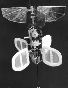 Fig No.2. 1: Toronto Mentor Project
Mentor proved the viability of the clap and fling method and the possibility that such a device could be stable while under remote control without any sort of autopilot. Mentor was designed to have a similar wingspan at 26cm but a much higher weight than our project calls for. Mentor had two configurations: one is an internal combustion engine (ICE) and another is battery power. The ICE method weighed 580g – one fourth of that being the fuel and motor. The battery powered method could not make use of relatively recently developed Lithium-Ion batteries but used more inefficient Nickel Cadmium. This caused a weight of 440g – over half of which was allocated to the motor and batteries. Mentor was never intended to emulate any actual bird or insect. It was proof that clap and fling method can be used to achieve stable lift and hover even with a relatively heavy aircraft. This stimulated the WPFly design as it directed the group in the direction of clap and fling research.
Fig No.2. 1: Toronto Mentor Project
Mentor proved the viability of the clap and fling method and the possibility that such a device could be stable while under remote control without any sort of autopilot. Mentor was designed to have a similar wingspan at 26cm but a much higher weight than our project calls for. Mentor had two configurations: one is an internal combustion engine (ICE) and another is battery power. The ICE method weighed 580g – one fourth of that being the fuel and motor. The battery powered method could not make use of relatively recently developed Lithium-Ion batteries but used more inefficient Nickel Cadmium. This caused a weight of 440g – over half of which was allocated to the motor and batteries. Mentor was never intended to emulate any actual bird or insect. It was proof that clap and fling method can be used to achieve stable lift and hover even with a relatively heavy aircraft. This stimulated the WPFly design as it directed the group in the direction of clap and fling research.
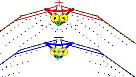
Fig No. 1.1 Air load
All the existing birds' feather fly mechanism works just like the red bird shown here. What is the difference between these two birds? There are two major differences The first difference is that the shaft of the feather, represented by green circles, is always away from the bird's body for living red bird, and the opposite for the fictitious blue bird. The second difference is that, the tip flight feather of the red bird is always fully visible if we look under the bird, and the other feathers always overlap one another. For the blue bird, the feather closest the bird body is fully visible and the rest is overlapped. I call the red bird feather arrangement a positive arrangement and the blue birds a negative arrangement. Also if the shaft of the feather is away from the bird, it will be called a positive feather and will be shown as a red feather. The blue birds flight feather is similar to the shaft of the feather & is at all times closer to the bird body. These types of feathers will be so-called negative feathers positive and negative for feathers and feather arrangements.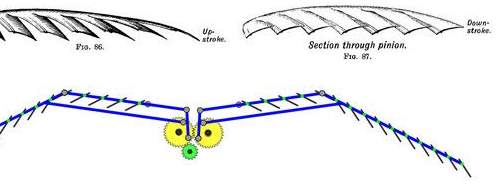
Fig No. 1.2Lilienthal model
If the feathers were performing as a flap, then why don’t we see birds in natural surroundings that be situated like the blue bird? Subsequently in two cases the flaps are unlocked in upstroke & there should be a 50/50 chance for together red and blue birds. However we do not see birds like the blue bird. Perhaps it’s because all birds, by good luck, derived from one type of bird and that is why we see only birds like red one in nature. As Lilienthal stated in his book, in nature any design is not an unintentional one. If environment chooses one design over the other, than there must be a firm intention for that. , when the feathers are opened in up stroke, the air is pushed toward under the bird’s body for the red bird, and away from the body for the blue bird. This is a vital difference.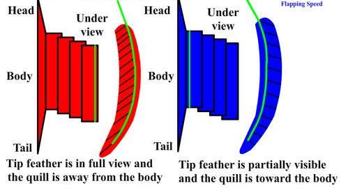
Fig No. 1.3 Quill structure
Think for a moment that the blue bird is on the ground, and a predator is approaching. The bird automatically flaps its wings to liftoff. First it is pushing its wings down, it is also pushing the air below its wing down, and it gains small elevation. But when the bird is in up stroke, the motion of the wing creates a vacuum under the wing. In the meantime the air under the wing has an outward inertia due to previous down stroke and does not have enough time to fill the gap. At the same time the air passing between the feathers going outward, blocking some of extra air coming toward under the wing; As a result the bird will be sucked downward. This will nullify all the altitude gain obtained during the wings down stroke and because it did not get enough air under the wing, the next down stroke will be fragile. The bird will uncontrollably flap its wings and fall down with each up stroke, and with each down stroke it will go up slightly. So birds that are like the blue bird could only fly if they were to jump from a branch off of a tree or from a cliff, taking off from the ground would be next to impossible for them. Now let's consider the red bird. When the wings are coming down, whatever happened with the blue bird will be repeated for the red bird as well. Though their up stroke is fairly dissimilar from blue birds. While the wings are going up, the opening in the feather will push the air under the bird’s body with a force that, not only will it will super charge the void with the air from above, it will also provide some upward force to the bird’s body and from falling downward. Also the air coming around and under the bird toward the void will be assisted by the air coming through the feathers above. I use the term super charge here, since this is closely what it is, the power used through the upstroke by the bird is converted directing more air atoms downward. It has two effects. Firstly it gives an upward lift to the bird similar to a Harrier jet. Secondly it gathers air below the wing for next downward stroke. The next downward stroke will take the bird upper. For the red bird, there are extra air atoms to be pushed downward for independently down stroke than the blue bird. Since it is supercharging air under its wing, the red bird will take off from ground very efficiently. Owing to the supercharging effect we assume the red bird’s feather organization as a positive arrangement. Feathers play a dynamic role throughout flight, both birds, red and blue, will advantage from the opening of flaps because it will reduce the drag throughout the upstroke. Supposing that both birds are flying the same speed during a travelling flight one may take up that there are no modifications between the two birds. Both birds will get fresh air underneath their wings due to their frontward speed. However, there is a slight difference between the airflow generated by the upstroke of the wings. When the blue bird’s feathers are visible in the upstroke external moving air pushes the tip of the feathers downward and tilts it in such a way that it generates an out and downward air drive. However, with the red bird this process will create a merging air flow as shown in the figure. This is very important event. As we know, when an object moves through the air with speed, it creates a low pressure region behind it, which causes drag that will reduce the speed of the moving object. Therefore the red bird’s air movement will try to fill the gap behind the bird, reducing the drag. Since the blue bird’s wings are pushing the air away from the body, it will not fill the gap behind it. This will cause considerable drag on the bird's movement. Also, the blue bird is trying to push the air outward, into still air, which might show resistance to it, and cause the bird to use more force and energy to push the air. On the other hand, the red bird wings are pushing the air toward a cavity, which needs air, so that it can be filled. In short satisfying the void behind a flying bird will decrease the drag and as a outcome energy consumption of upward moving wings will be decreased. CHAPTER 2 LITERATURE REVIEW2.1 University of Toronto Mentor
Mentor at the University of Toronto was among the first radio controlled MAV’s to achieve hover using 4 wings in a clap and fling motion, as shown below in Figure 2.
Fig No.2. 1: Toronto Mentor Project
Mentor proved the viability of the clap and fling method and the possibility that such a device could be stable while under remote control without any sort of autopilot. Mentor was designed to have a similar wingspan at 26cm but a much higher weight than our project calls for. Mentor had two configurations: one is an internal combustion engine (ICE) and another is battery power. The ICE method weighed 580g – one fourth of that being the fuel and motor. The battery powered method could not make use of relatively recently developed Lithium-Ion batteries but used more inefficient Nickel Cadmium. This caused a weight of 440g – over half of which was allocated to the motor and batteries. Mentor was never intended to emulate any actual bird or insect. It was proof that clap and fling method can be used to achieve stable lift and hover even with a relatively heavy aircraft. This stimulated the WPFly design as it directed the group in the direction of clap and fling research.
2.2 Delfly
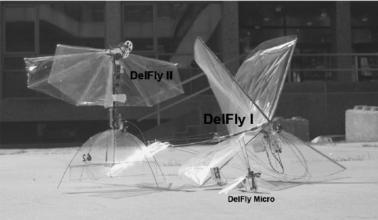 Fig No. 2.2 DelFly II (Left), DelFly I (Right), DelFly Micro (Front) (De Croon, G. 2009)
Delfly has existed in three major forms. The first, Delfly I, is an MAV capable of forward flight as well as slow near-hovering flight. DelFly I weighed 21g with a wingspan of 50cm. similar to all prototypes, Delfly I suffered from a number of problems related to stability, control, and reliability. inverted V tail allowed for stable forward flight but there was difficulty in controlling attitude changes. Delfly I’s drive train was designed so that as the motor turned, a Z shaped crank would rotate causing the wings to move up and down. This method was difficult to sync and as a result the craft experiencd slight rolling during flight. Also, the motor did not possess a high efficiency and also, it was not brushless,and caused it to build up heat during flight. This decreased reliability caused for frequent motor replacements.
Fig No. 2.2 DelFly II (Left), DelFly I (Right), DelFly Micro (Front) (De Croon, G. 2009)
Delfly has existed in three major forms. The first, Delfly I, is an MAV capable of forward flight as well as slow near-hovering flight. DelFly I weighed 21g with a wingspan of 50cm. similar to all prototypes, Delfly I suffered from a number of problems related to stability, control, and reliability. inverted V tail allowed for stable forward flight but there was difficulty in controlling attitude changes. Delfly I’s drive train was designed so that as the motor turned, a Z shaped crank would rotate causing the wings to move up and down. This method was difficult to sync and as a result the craft experiencd slight rolling during flight. Also, the motor did not possess a high efficiency and also, it was not brushless,and caused it to build up heat during flight. This decreased reliability caused for frequent motor replacements.
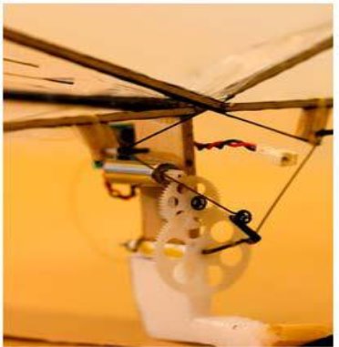 Fig No.2.3 Delfly I Drivetrain (Bruggeman, B. 2010)
The project was later designed again with many of these faults corrected into the DelFly II. This model was smaller and lighter, weighing only 16g with a wingspan of 28cm. The drive train was completely redesigned to eliminate the rolling motion present in DelFly I. Additionally, the revamped design included custom-made high-performance components, such as a custom brushless motor which is capable of much higher efficiencies and a microcontroller to experiment with autonomous flight. The tail was designed again to use a cruciform tail seen on most model aircrafts to allow to pitch and yaw motions which the vehicle was previously incapable of. This vehicle was capable of both indoor and outdoor flight, and also stability required to have a camera as payload. This design was the subject of numerous research projects to optimize the flapping motion and increasing lift as well as various controls and autonomous flight experiments.
Fig No.2.3 Delfly I Drivetrain (Bruggeman, B. 2010)
The project was later designed again with many of these faults corrected into the DelFly II. This model was smaller and lighter, weighing only 16g with a wingspan of 28cm. The drive train was completely redesigned to eliminate the rolling motion present in DelFly I. Additionally, the revamped design included custom-made high-performance components, such as a custom brushless motor which is capable of much higher efficiencies and a microcontroller to experiment with autonomous flight. The tail was designed again to use a cruciform tail seen on most model aircrafts to allow to pitch and yaw motions which the vehicle was previously incapable of. This vehicle was capable of both indoor and outdoor flight, and also stability required to have a camera as payload. This design was the subject of numerous research projects to optimize the flapping motion and increasing lift as well as various controls and autonomous flight experiments.
2.3 Harvard University RoboBee
Robert Wood and a team of four members at Harvard University newly developed a very small robot that very closely mimics a flapping insect. With the use of piezoelectric actuators, the wings have three degrees of freedom. The robot does not have a tail and makes its altitude changes through manipulating its wings. This is the same as how an actual insect flies and controls itself. The robot suffers from scrambling issues and the device requires external power, for no normally available power source is small enough to fit onboard. The lack of a tail and any sort of control sensor also results in unstable flight; most tests only run for a few seconds until the aircraft loses control. RoboBee is a ace of engineering, using novel contraction and manufacturing techniques; however, with a wingspan of just one inch, its scale is smaller than the scope of this project and was not heavily considered in our design.2.4 Clap and Fling
The clap and fling is a method of flapping that generates more lift than conventional flapping of wings. It can be seen being used in nature by sparrows and some species of fly. The clap and fling works by swiftly bringing two wings together beginning with the primary edge. The leading edges touch and elastic wings will follow in a sensation known as feathering. As the wings come together air is pushed out the back generating thrust, which when angled properly will create lift. When the wings are together they instantly begin to whither apart letting air to rush in from the opposite. This suction also creates thrust, pulling the wings forward. From an outside viewpoint the air is being dispersed around the wings, which creates lift under the Kutta situation. The wing is quickly moving though air causing an unsteady flow and vortices creating around the leading edge. These vortices will interrelate in ways not yet agreed with the vortices coming off the edge of the wing generating extra lift. All of these occurrence together are illustrated below.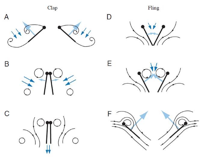 Fig No. 2.4 Clap and fling
2.5 WING DESIGN BY HARRIS MODEL
The wing details vary, but in all cases they are characterized by consisting of three hinged panels with chord wise rigid ribs and constant span wise lengths. The three panel feature, which was invented by Harris, serves to balance the time-varying lift seen by the fuselage. The center portion of the wing flap in one direction while the outer portions flapp in the opposite direction. Whereas it is not possible to completely balance the inertial and aerodynamic loads for all flight conditions, this tendency to achieve a dynamic balance would be a valuable feature for a human carrying aircraft. Moreover, for ornithopters of any scale, the three panel wing provides evening out the power required from the engine during the flapping cycle. That is, the size of engines for ornithopters is determined by the top power required during the cycle. For customary two panel designs, the power required for the down stroke may be several times greater than the power required for the upstroke. Therefore, the required engine may be much larger than average power considerations would dictate. This effects in an aircraft heavier than a fixed wing propeller driven aeroplane of similar performance. Later, C designers have pursued ways to store energy on the upstroke. For birds and bats, some storage may be provided by their tendons. It is more probable, though, that the upstroke is the period of rest required by the down stroke muscles. Such rest is not needed by mechanical systems, and energy storage has typically used elastic means, such as the bungee cords incorporated into the AeroVironment pterosaur replica. However, an ornithopter isn't required to be a scale model of an animal, and the three panel wing thus provides an attractive means for power evening as well as dynamic balance.
.
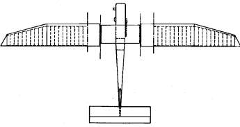 Fig No. 2.5 Harris model (Top view)
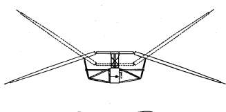 Fig No. 2.6 Three panel model
The wing's flapping indication is activated through the center panel's vertical oscillation & driven in simple harmonic motion by a mechanism. The middle panel is built to be rigid in bending and twisting, and includes a simple flat-bottom aerofoil (nominally, a Clark-Y). It was initially imagined that the center panel would require a direct pitch articulation in conjunction with its vertical (plunging) motion. As it was found pterosaur model. An ornithopter isn't essential to be a scale model of an animal, and the three panel wing thus provides an attractive means for power evening as well as active balance. The wing's flapping motion is triggered through the center panel's vertical oscillation. Driven in simple harmonic motion by a mechanism. The center panel is constructed to be rigid in bending and twisting, and incorporates a simple flat-bottom aero foil (nominally, a Clark-Y). It was originally envisaged that the center panel would require a direct pitch articulation in conjunction with its vertical (plunging) motion; but it was found, as described later, that it operated most effectively in plunging only. The external panels operate in a span wise- seesaw way and determined at one end by hinge connections to the center panel. There were two systems of support struts and hinges for the outer panels in the course of their evolution, from 1985 to 1987 the strut assembly was rigid, with a single hinge connection to the outer panel. The kinematic requirements were then met by means of span wise sliding hinges to the centre panel. That is, the driving hinges on the end of an outer panel had lubricated cylindrical extensions which slid, piston-like, into the center panel’s hollow spar tubes. This demonstrated to be a very consistent system, but it had the aerodynamic disadvantage of producing large, variable. Span wise gaps in the middle of the center and outer panels. Pieces of stretchable fabric were used to cover the gaps; but this, aerodynamically, was not a particularly efficient solution. In 1989, the support struts were changed to a system incorporating hinged vertical links. These allowed the sliding hinges at the centre panel to be replaced with simple non-sliding units. The gap then remained small and could be aerodynamically sealed with narrow abutting extension strips attached to the end faces of the panels. This system operated consistently during the development of the flight tests in 1989 and 1991. The external panels between 1985 and 1987 united a single-surface aerofoil and two spar assembly Attached to the ribs were short spanwise tubular pieces through which the spars accepted. The original idea was that since the single sur-face aerofoil has torsional compliance, the outer panel's pitching distribution could be driven by spanwisc rocking of the two spars. wolb JIM a WM AM;Met at Midi 4CCIIICU woe a ltddlMaLPIC (=Sign. Later, as it became obvious from flight tests and the developing analysis that the wing had extreme torsional compliance, the rear spar was extended and a portion of it changed to a 1/4 in diameter fibreglass rod. In fact, there was a flight test session where the rear spar was a 1/4 in diameter solid carbonfibre rod. Guided by the analysis, the ornithopter's performance improved steadily during this course of development. However, it was never near to achieving sustained flight. That is. The flight mode was a "powered glide", where the flapping would clearly extend the dis-tance flown compared with the non-flapping cases, but it would not climb or maintain altitude. The reason, revealed by windtunnel tests01), was that the actual aerodynamic characteristics fell short of the estimated values used as inputs in the analysis. In specific, the aerofoil had high chord-wise drag (Co = 0.063). Poor leading-edge suction en, = 0-29). It detached flow on one side or the other at all angles of outbreak. In comparison with modem double surface sections, this aerofoil was a very poor performer (typically, for a Reynolds number of 2 x 10³, a modem aerofoil should give Co= 0.012 and r1, 44 0.90). It was desired, however, to retain the single-surface feature because of its torsional compliance, and to find ways to improve such an aerofoil's aerodynamic performance.
2.6 Mechanism
A mechanism is a device intended to transform input forces and movement into an anticipated set of output forces and movement. Mechanisms generally has moving constituents such as gears, gear trains, belt, chain drives, cam and follower mechanisms, and linkages. Friction devices such as brakes, clutches and structural components such as the frame, bearings ,bfasteners, springs, lubricants and seals.
The German scientist delivers the explanation "a machine is an arrangement of resistant bodies so arranged that by their means the mechanical forces of nature can be compelled to do work attended by certain determinate motion." In this context, his use of machine is commonly understood to mean mechanism.
The combination of force and movement describes power, and a mechanism is intended to achieve power. In order to reach a wanted set of forces and movement.
A mechanism is usually a larger process or mechanical system. Sometimes a complete machine may be mentioned to as a mechanism. Examples are the steering mechanism in a car and the winding mechanism of a wristwatch. Multiple mechanisms are machines.
Fig No. 2.6 Three panel model
The wing's flapping indication is activated through the center panel's vertical oscillation & driven in simple harmonic motion by a mechanism. The middle panel is built to be rigid in bending and twisting, and includes a simple flat-bottom aerofoil (nominally, a Clark-Y). It was initially imagined that the center panel would require a direct pitch articulation in conjunction with its vertical (plunging) motion. As it was found pterosaur model. An ornithopter isn't essential to be a scale model of an animal, and the three panel wing thus provides an attractive means for power evening as well as active balance. The wing's flapping motion is triggered through the center panel's vertical oscillation. Driven in simple harmonic motion by a mechanism. The center panel is constructed to be rigid in bending and twisting, and incorporates a simple flat-bottom aero foil (nominally, a Clark-Y). It was originally envisaged that the center panel would require a direct pitch articulation in conjunction with its vertical (plunging) motion; but it was found, as described later, that it operated most effectively in plunging only. The external panels operate in a span wise- seesaw way and determined at one end by hinge connections to the center panel. There were two systems of support struts and hinges for the outer panels in the course of their evolution, from 1985 to 1987 the strut assembly was rigid, with a single hinge connection to the outer panel. The kinematic requirements were then met by means of span wise sliding hinges to the centre panel. That is, the driving hinges on the end of an outer panel had lubricated cylindrical extensions which slid, piston-like, into the center panel’s hollow spar tubes. This demonstrated to be a very consistent system, but it had the aerodynamic disadvantage of producing large, variable. Span wise gaps in the middle of the center and outer panels. Pieces of stretchable fabric were used to cover the gaps; but this, aerodynamically, was not a particularly efficient solution. In 1989, the support struts were changed to a system incorporating hinged vertical links. These allowed the sliding hinges at the centre panel to be replaced with simple non-sliding units. The gap then remained small and could be aerodynamically sealed with narrow abutting extension strips attached to the end faces of the panels. This system operated consistently during the development of the flight tests in 1989 and 1991. The external panels between 1985 and 1987 united a single-surface aerofoil and two spar assembly Attached to the ribs were short spanwise tubular pieces through which the spars accepted. The original idea was that since the single sur-face aerofoil has torsional compliance, the outer panel's pitching distribution could be driven by spanwisc rocking of the two spars. wolb JIM a WM AM;Met at Midi 4CCIIICU woe a ltddlMaLPIC (=Sign. Later, as it became obvious from flight tests and the developing analysis that the wing had extreme torsional compliance, the rear spar was extended and a portion of it changed to a 1/4 in diameter fibreglass rod. In fact, there was a flight test session where the rear spar was a 1/4 in diameter solid carbonfibre rod. Guided by the analysis, the ornithopter's performance improved steadily during this course of development. However, it was never near to achieving sustained flight. That is. The flight mode was a "powered glide", where the flapping would clearly extend the dis-tance flown compared with the non-flapping cases, but it would not climb or maintain altitude. The reason, revealed by windtunnel tests01), was that the actual aerodynamic characteristics fell short of the estimated values used as inputs in the analysis. In specific, the aerofoil had high chord-wise drag (Co = 0.063). Poor leading-edge suction en, = 0-29). It detached flow on one side or the other at all angles of outbreak. In comparison with modem double surface sections, this aerofoil was a very poor performer (typically, for a Reynolds number of 2 x 10³, a modem aerofoil should give Co= 0.012 and r1, 44 0.90). It was desired, however, to retain the single-surface feature because of its torsional compliance, and to find ways to improve such an aerofoil's aerodynamic performance.
2.6 Mechanism
A mechanism is a device intended to transform input forces and movement into an anticipated set of output forces and movement. Mechanisms generally has moving constituents such as gears, gear trains, belt, chain drives, cam and follower mechanisms, and linkages. Friction devices such as brakes, clutches and structural components such as the frame, bearings ,bfasteners, springs, lubricants and seals.
The German scientist delivers the explanation "a machine is an arrangement of resistant bodies so arranged that by their means the mechanical forces of nature can be compelled to do work attended by certain determinate motion." In this context, his use of machine is commonly understood to mean mechanism.
The combination of force and movement describes power, and a mechanism is intended to achieve power. In order to reach a wanted set of forces and movement.
A mechanism is usually a larger process or mechanical system. Sometimes a complete machine may be mentioned to as a mechanism. Examples are the steering mechanism in a car and the winding mechanism of a wristwatch. Multiple mechanisms are machines.
Fig No. 2.7 Spur gears
The transmission of rotation in the middle of contacting toothed wheels can be traced back to the Antikythera mechanism. Drawings by the renaissance scientist Georgius Agricola show gear trains with cylinder-shaped teeth. The presentation of the involute tooth produced a regular gear design that provides a constant speed ratio. Some main features of gears and gear trains are:
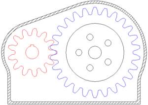 Fig No. 2.8 Gear engage
The velocity ratio that teeth give gears offers a benefit over other drives (such as traction drives and V-belts) in exactness machines like watches that depend on an exact velocity ratio. Some cases where driver and follower are proximal, gears also have an advantage over other drives in reduced number of parts required. The gears are more expensive to manufacture and their lubrication requirements may execute a higher operating cost.
Fig No. 2.8 Gear engage
The velocity ratio that teeth give gears offers a benefit over other drives (such as traction drives and V-belts) in exactness machines like watches that depend on an exact velocity ratio. Some cases where driver and follower are proximal, gears also have an advantage over other drives in reduced number of parts required. The gears are more expensive to manufacture and their lubrication requirements may execute a higher operating cost.
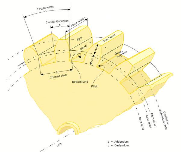 Fig No. 2.9 Gear terminology
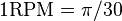 Rad/second
 in metric units or
 in imperial units.
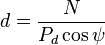
 Where, m is the module and p the circular pitch. The units of module are millimeters; Module is sometimes used with the units of inches. When the diametral pitch, DP.
 in conventional metric units.
The distance between the two axis becomes
in conventional metric units.
The distance between the two axis becomes
 where a is the axis distance, z1 and z2 are the number of components (teeth) for each of the two wheels (gears). These numbers are often chosen among peaks to create an even contact between every cog of both wheels, and in so doing avoid unnecessary wear and damage. An identical gear wear is obtained by approving the number of teeth of the two gears meshing together are relatively key to each other. This occurs when the greatest common divisor (GCD) of each gear tooth count matches 1, e.g. GCD(16,25)=1; If a 1:1 gear ratio is sought after a relatively prime gear may be put in between the two gears; this maintains the 1:1 ratio but reverses the gear direction. A second relatively prime gear could also be inserted to return the original rotational direction while keeping uniform wear with all 4 gears in this case. Mechanical engineers at least in continental Europe use the module instead of circular pitch. The module, just like the circular pitch, can be used for all types of cogs, not just evolving based straight cog.
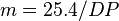
 Fig No.2.10 Windshield wiper
The four bar linkage is the simplest and the most useful mechanism. As we mentioned before, a mechanism composed of rigid bodies and lower pair is called a linkage . In planar mechanisms, there are two kinds of lower pair’s prismatic and revolute pairs.
The simplest closed loop linkage is the four bar linkage which has four members, 3 moving links, one fixed link and four pin joints. A linkage that has at least one fixed link is known as mechanism. The following example of a four bar linkage was formed in SimDesign.
Fig No.2.10 Windshield wiper
The four bar linkage is the simplest and the most useful mechanism. As we mentioned before, a mechanism composed of rigid bodies and lower pair is called a linkage . In planar mechanisms, there are two kinds of lower pair’s prismatic and revolute pairs.
The simplest closed loop linkage is the four bar linkage which has four members, 3 moving links, one fixed link and four pin joints. A linkage that has at least one fixed link is known as mechanism. The following example of a four bar linkage was formed in SimDesign.
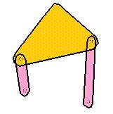 Fig No. 2.11 Four bar linkage in SimDesign
This mechanism has three moving links. Two of the links are restrained to the frame which is not shown in this image. In SimDesign, links can be nailed to the background thereby making them into the frame.
How many DOF does this mechanism have? If we need it to have just unique, we can enact one constraint on the linkage and it will have a fixed motion. The four bar linkage is the simplest and the most useful mechanism.
A mechanism is composed of inelastic bodies and lower pairs called linkages. In planar mechanisms there are only two kinds of lower pairs: turning pairs and prismatic pairs.
Functions of Linkages
The purpose of a link mechanism is to produce oscillating, rotating or reciprocating motion from the rotation of a crank or vice versa. Stated more specifically linkages may be used to convert:
Fig No. 2.11 Four bar linkage in SimDesign
This mechanism has three moving links. Two of the links are restrained to the frame which is not shown in this image. In SimDesign, links can be nailed to the background thereby making them into the frame.
How many DOF does this mechanism have? If we need it to have just unique, we can enact one constraint on the linkage and it will have a fixed motion. The four bar linkage is the simplest and the most useful mechanism.
A mechanism is composed of inelastic bodies and lower pairs called linkages. In planar mechanisms there are only two kinds of lower pairs: turning pairs and prismatic pairs.
Functions of Linkages
The purpose of a link mechanism is to produce oscillating, rotating or reciprocating motion from the rotation of a crank or vice versa. Stated more specifically linkages may be used to convert:
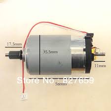 Fig No. 2.12 DC Motor
The rotor is placed within the force field caused by 2 permanent magnets. By pertaining to things, each side of the wire loop can have a force on them. attempting to create the wire loop rotate. this is applied to the loop through the commentator, that is shown as 2 items of metal shaped into a hoop within the figure. Current is applied to the commentator by stationary C blocks, known as brushes, that rub against the commentator ring. The loop can still rotate anticlockwise till it's vertical. At now, the stationary brushes can apply current round the loop nomore as a result of they're going to be to bear with the gap between the commentator segments, however the inertia of the loop keeps it going very little additional, till the DC provide reconnects to the commentator segments, and therefore the current then goes round the loop within the wrong way. The force although remains within the same direction and therefore the loop continues to rotate.
Fig No. 2.12 DC Motor
The rotor is placed within the force field caused by 2 permanent magnets. By pertaining to things, each side of the wire loop can have a force on them. attempting to create the wire loop rotate. this is applied to the loop through the commentator, that is shown as 2 items of metal shaped into a hoop within the figure. Current is applied to the commentator by stationary C blocks, known as brushes, that rub against the commentator ring. The loop can still rotate anticlockwise till it's vertical. At now, the stationary brushes can apply current round the loop nomore as a result of they're going to be to bear with the gap between the commentator segments, however the inertia of the loop keeps it going very little additional, till the DC provide reconnects to the commentator segments, and therefore the current then goes round the loop within the wrong way. The force although remains within the same direction and therefore the loop continues to rotate.
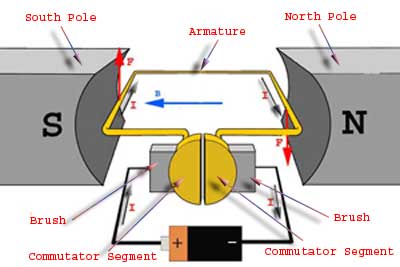 Fig No.2.13: The Operation of DC Motor
2.9.1 DC Motor Voltage
DC motors ar non-polarized - which means that one will reverse voltage with none dangerous things happening. Typical DC motors ar rated from concerning 6V-12V. The larger ones ar typically 24V or additional. Except for the needs of this project, do keep within the 6V-12V vary. It’s expressed that voltage is directly associated with motor torsion. High voltage produces higher torsion. A DC motor is rated at the voltage wherever it's most effective at running. If only a few volts ar applied, it simply will not work. If an excessive amount of is applied, can|it'll} overheat and also the coils will soften. Therefore the general rule is to use as near the rated voltage of the motor. However don’t exceed 12V motors unless torsion is crucial badly.
2.9.2 DC Motor Current
As with all electronic equipment, one should listen to current. Too little, and it simply will not work. Too much, the motor can meltdown. Once shopping for a motor, there ar 2 current ratings one ought to listen to. The primary is working current. this is often the typical quantity of current the motor is anticipated to draw beneath a typical force. Multiply this range by the valued voltage and also the average power draw necessary to run the motor is obtained. The opposite current rating that one must listen to is that the stall current. This is often once the motor is power up, and enough force is place to force it to prevent rotating. This is often the utmost quantity of current the motor can ever draw, and therefore the utmost quantity of power too. So, one should style all management electronic equipment capable of handling this stall current. Also, if the motor is continually run, or run it over the rated voltage, it's knowing sink to stay the motor's coils from melting.
2.9.3 DC Motor Power Rating
All motors are rated at definite wattage. Wattage is energy and incompetence of energy conversion is directly connected to heat output. Too much heat, the motor coils melt. So the manufacturers of motors know how much wattage will cause motor failure, and post this on the motor specification sheets. The equation is:
Power (watts) = Voltage * Current
Increase voltage and extent current until the power is about -90% below the given power rating.
2.9.10 DC Motor Torque
Torque is well-defined as that force which inclines to harvest and maintain rotation. The purpose of torque in a DC motor is to provide the mechanical output or effort the piece of apparatus that the DC motor is committed to. There are two torque value ratings which must been pay attention to. The first is the operating torque. This is the torque the motor is calculated to give. Usually it is the listed torque value. The other rated value is stall torque. This is the torque required to stop the motor from rotating. The torque developed by the motor can be determined using Equation:
T = KQI,
Where
T = torque
K = a constant depending on physical size of motor
Q = field flux, number of lines of force per pole
I = armature current
To buy a DC motor, there will be two torque value ratings to which attention must be paid. The first is operating torque. This is the torque the motor is considered to give. Usually it is the listed torque value. The other rated value is stall torque. This is the torque necessary to stop the motor to rotate. If one need a little more speed, going 20% above the rated motor voltage value is fairly safe. But, that this is less efficient, and the motor should be heat- sinked.
Velocity Velocity is very complex when it comes to DC motors. The general rule is motors run the most efficient when run at the highest possible speeds. Obviously however this is not possible. There are times to run the motor slowly. Just like car, it won't to keep the car constantly at high speed. The voltage and applied torque resistance clearly affects speed.
PMDC motor:
This motor using for this project PMDC motor In a dc motor, an armature rotates inside a magnetic field. The working principle of DC motor is based on the point that whenever a current carrying conductor is placed inside magnetic, there will be mechanical force experienced by that conductor. All kinds of DC work in this principle only. Therefore for constructing a dc motor it is necessary to establish a magnetic field. The magnetic field is obviously established by means of magnet. The magnet can by any types i.e. it may be electromagnet or it may be a permanent magnet. When permanent magnet is used to create magnetic field in a DC motor, the motor is referred as permanent magnet dc motor or PMDC motor. Did you ever uncover any battery operated toy, if you had uncovered, you had obviously found a battery-operated motor inside it. This battery operated motor is nothing but a permanent magnet dc motor or PMDC motor. These types of motors are basically simple in construction. These motors are commonly used as starter motor in automobiles, windshield wipers, washer, for blowers used in heaters and air conditioners, to raise and lower windows, it also extensively used in toys. As the magnetic field strength of a permanent magnet is fixed it cannot be organized externally, field control of this type of dc motor cannot be possible. Thus permanent magnet dc motor is used where there is no need of speed control of motor by means of controlling its field. Minor fractional and substitute fractional kW motors are now constructed with permanent magnet.
Fig No.2.13: The Operation of DC Motor
2.9.1 DC Motor Voltage
DC motors ar non-polarized - which means that one will reverse voltage with none dangerous things happening. Typical DC motors ar rated from concerning 6V-12V. The larger ones ar typically 24V or additional. Except for the needs of this project, do keep within the 6V-12V vary. It’s expressed that voltage is directly associated with motor torsion. High voltage produces higher torsion. A DC motor is rated at the voltage wherever it's most effective at running. If only a few volts ar applied, it simply will not work. If an excessive amount of is applied, can|it'll} overheat and also the coils will soften. Therefore the general rule is to use as near the rated voltage of the motor. However don’t exceed 12V motors unless torsion is crucial badly.
2.9.2 DC Motor Current
As with all electronic equipment, one should listen to current. Too little, and it simply will not work. Too much, the motor can meltdown. Once shopping for a motor, there ar 2 current ratings one ought to listen to. The primary is working current. this is often the typical quantity of current the motor is anticipated to draw beneath a typical force. Multiply this range by the valued voltage and also the average power draw necessary to run the motor is obtained. The opposite current rating that one must listen to is that the stall current. This is often once the motor is power up, and enough force is place to force it to prevent rotating. This is often the utmost quantity of current the motor can ever draw, and therefore the utmost quantity of power too. So, one should style all management electronic equipment capable of handling this stall current. Also, if the motor is continually run, or run it over the rated voltage, it's knowing sink to stay the motor's coils from melting.
2.9.3 DC Motor Power Rating
All motors are rated at definite wattage. Wattage is energy and incompetence of energy conversion is directly connected to heat output. Too much heat, the motor coils melt. So the manufacturers of motors know how much wattage will cause motor failure, and post this on the motor specification sheets. The equation is:
Power (watts) = Voltage * Current
Increase voltage and extent current until the power is about -90% below the given power rating.
2.9.10 DC Motor Torque
Torque is well-defined as that force which inclines to harvest and maintain rotation. The purpose of torque in a DC motor is to provide the mechanical output or effort the piece of apparatus that the DC motor is committed to. There are two torque value ratings which must been pay attention to. The first is the operating torque. This is the torque the motor is calculated to give. Usually it is the listed torque value. The other rated value is stall torque. This is the torque required to stop the motor from rotating. The torque developed by the motor can be determined using Equation:
T = KQI,
Where
T = torque
K = a constant depending on physical size of motor
Q = field flux, number of lines of force per pole
I = armature current
To buy a DC motor, there will be two torque value ratings to which attention must be paid. The first is operating torque. This is the torque the motor is considered to give. Usually it is the listed torque value. The other rated value is stall torque. This is the torque necessary to stop the motor to rotate. If one need a little more speed, going 20% above the rated motor voltage value is fairly safe. But, that this is less efficient, and the motor should be heat- sinked.
Velocity Velocity is very complex when it comes to DC motors. The general rule is motors run the most efficient when run at the highest possible speeds. Obviously however this is not possible. There are times to run the motor slowly. Just like car, it won't to keep the car constantly at high speed. The voltage and applied torque resistance clearly affects speed.
PMDC motor:
This motor using for this project PMDC motor In a dc motor, an armature rotates inside a magnetic field. The working principle of DC motor is based on the point that whenever a current carrying conductor is placed inside magnetic, there will be mechanical force experienced by that conductor. All kinds of DC work in this principle only. Therefore for constructing a dc motor it is necessary to establish a magnetic field. The magnetic field is obviously established by means of magnet. The magnet can by any types i.e. it may be electromagnet or it may be a permanent magnet. When permanent magnet is used to create magnetic field in a DC motor, the motor is referred as permanent magnet dc motor or PMDC motor. Did you ever uncover any battery operated toy, if you had uncovered, you had obviously found a battery-operated motor inside it. This battery operated motor is nothing but a permanent magnet dc motor or PMDC motor. These types of motors are basically simple in construction. These motors are commonly used as starter motor in automobiles, windshield wipers, washer, for blowers used in heaters and air conditioners, to raise and lower windows, it also extensively used in toys. As the magnetic field strength of a permanent magnet is fixed it cannot be organized externally, field control of this type of dc motor cannot be possible. Thus permanent magnet dc motor is used where there is no need of speed control of motor by means of controlling its field. Minor fractional and substitute fractional kW motors are now constructed with permanent magnet.
Fig No. 2.14 Construction of Permanent Magnet DC Motor or PMDC Motor
As it is specified in name of permanent magnet dc motor, the field poles of this motor are basically made of permanent magnet.
A PMDC motor mainly consists of two parts. A stator and an armature. Here the stator which is a steel cylinder. The magnets are mounted in the inner periphery of this cylinder. The permanent magnets are mounted in a way that the N – pole and S – pole of each magnet are alternatively faced towards armature as shown in the figure below. That means, if N – pole of one magnet is faced towards armature then S – pole of very next magnet is faced towards armature.
In addition to hold the magnet on its inner border, the steel cylindrical stator also serves as low reluctance return path for the magnetic flux. Although field coil is not required in permanent magnet dc motor but still it is sometimes found that they are used along with permanent magnet. Incase permanent magnets lose their strength, these lost magnetic strengths can be recompensed by field excitation through these field coils. Generally, rare earth hard magnetic materials are used for these permanent magnet.
Rotor: The rotor of PMDC motor is similar to other DC motor. The rotor or armature of permanent magnet dc motor also consists of core, windings and commentator. Armature core is made of many varnish insulated, slotted circular laminated steel sheets. By fixing these circular steel sheets one by one, a cylindrical shaped slotted armature core is formed. The laminated steel sheets which are varnish insulated are used to reduce eddy current loss in armature of permanent magnet dc motor. These slots on the outer periphery of the armature core are used for housing armature conductors in them. The armature conductors are connected in a manner that gives rise to armature winding. The end terminals of the winding are connected to the commentator segments placed on the motor shaft. In other dc motor, carbon and graphite brushes are put along with the spring compression on the commentator divisions to supply current to the armature.
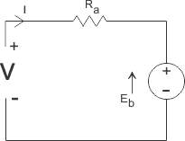
 I, is armature current and R is armature resistance of the motor.
Eb is the back emf and V is the supply voltage.
Benefits of Permanent Magnet DC Motor or PMDC Motor
PMDC motor has some advantages over other types of dc motors. They are:
I, is armature current and R is armature resistance of the motor.
Eb is the back emf and V is the supply voltage.
Benefits of Permanent Magnet DC Motor or PMDC Motor
PMDC motor has some advantages over other types of dc motors. They are:
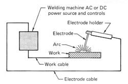 Fig No. 2.16 Arc welding
Duty cycle is a welding apparatus specification which explains the number of minutes, within a 10-minute period, during which a given arc welder can safely be used. For example, an 80A welder with a 60% duty cycle must be "rested" for at least 4 minutes after 6 minutes of nonstop welding. Failure to spot duty cycle confines could damage the welder. Commercial and professional-grade welders normally have a 100% duty cycle.
CHAPTER 3
DESIGN AND SELECTION OF PARTS
The group reviewed through the literature to gain insight into the motion of flapping wings and how they generate lift. Previous projects involving flapping wing MAVs inspired the group.
The modeling process began with a basic idea of what the group was hoping to achieve with this project – a relatively small flapping wing vehicle capable of vertical takeoff and landing, hover, and horizontal flight. Through research, that it was decided that mimicking a two-wing bird or insect would be rather difficult and unreasonable, for these animals move in a very complex manner. Through more research and the discovery of the clap-and-fling method of flight, the group decided upon a two-wing. This is easier to model and manufacture compared to the motion required for a two-wing vehicle to take flight.
As the group continued to model the wings, the next step was to choose which components and materials would be used in the design. In the development of the body, and wings, the group researched materials that were lightweight, yet durable enough to withstand impact and rapid movement. The group also researched materials that could be manufactured to conserve the financial budget. Also involved in the design are several electronic components: a battery and a motor. These components must power the flapping the wings. Detailed descriptions of these components and their purpose, as well as why the group chose each specific item, will be included in this section.
Fig No. 2.16 Arc welding
Duty cycle is a welding apparatus specification which explains the number of minutes, within a 10-minute period, during which a given arc welder can safely be used. For example, an 80A welder with a 60% duty cycle must be "rested" for at least 4 minutes after 6 minutes of nonstop welding. Failure to spot duty cycle confines could damage the welder. Commercial and professional-grade welders normally have a 100% duty cycle.
CHAPTER 3
DESIGN AND SELECTION OF PARTS
The group reviewed through the literature to gain insight into the motion of flapping wings and how they generate lift. Previous projects involving flapping wing MAVs inspired the group.
The modeling process began with a basic idea of what the group was hoping to achieve with this project – a relatively small flapping wing vehicle capable of vertical takeoff and landing, hover, and horizontal flight. Through research, that it was decided that mimicking a two-wing bird or insect would be rather difficult and unreasonable, for these animals move in a very complex manner. Through more research and the discovery of the clap-and-fling method of flight, the group decided upon a two-wing. This is easier to model and manufacture compared to the motion required for a two-wing vehicle to take flight.
As the group continued to model the wings, the next step was to choose which components and materials would be used in the design. In the development of the body, and wings, the group researched materials that were lightweight, yet durable enough to withstand impact and rapid movement. The group also researched materials that could be manufactured to conserve the financial budget. Also involved in the design are several electronic components: a battery and a motor. These components must power the flapping the wings. Detailed descriptions of these components and their purpose, as well as why the group chose each specific item, will be included in this section.
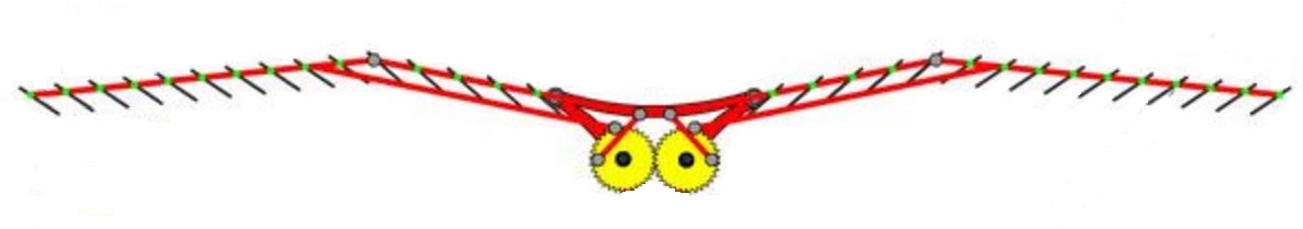 Fig No.3.1 Isometric View of the Model
3.1 Body
The group finally constricted the field to two different materials. The first wood and the second iron rods. The wood was used but it failed to maintain its shape due to the vibrations. Thus wood failed to maintain its perfect frame dimensions when drivetrain is fixed. Then mild steel plates are used to make the frame which maintained its shape. The shape of the frame was designed to be simple. There is another section designed to mount the drive train and hinge. The frame is made of mild steel bars. The frame shape was finalized for ease of manufacturing and for simplicity as well. The finalized drive train was used to design the front part of the frame and a very basic final design was chosen.
3.2 Wings
For a design involving two wings, it is crucial for each wing to mimic the motion of bird. For this purpose, the group decided to research thin plastic films to comprise the wing, and iron rod spars to provide support and allow for the clap and fling effect.
While researching different wing shapes, the grouptried to research different wings of various birds and tried to understand its movement and concluded that spars to bend closer to the leading edge and preventing the behind corners of the wings from being unsteady during flapping.
To finalize the size of the wings, the group used a lift equation found through texts. This equation is an assessed equation derived through testing of rectangular flapping wings.
After finalizing the size and shape of the wings, the group researched materials to form the spars and membrane. These materials need not to be as light in weight but strong enough to flap without failing.
Taking these demanding applications into account, the group researched common durable materials such as iron rods, wood and plastic. All three materials would be strong enough to support the wings, but the group chose iron rods, the strongest of the three. Iron rods can be cut and welded easily whereas the wood was not strong enough as the cracks appear due to machining operations. Iron rods are comparatively higher in price; however, after reviewing the budget, the group decided that it would be worth it is for its strength and reliability. Once we selected iron rods as the spar material, it was time to focus on a membrane that could be effectively attached to it. And the group decided to use plastic boards as the membrane.
3.3 Hinge
A hinge is necessary to hold the two 0ings together and allow a flapping motion that brings the leading edges together. The group selected mild steel bars as a material. This would withstand the rapid movement without failure.
This simpler hinge was attached to the frame by welding.
3.4 Drive Train
The motion of the hinge will be created by a drive train connected to the motor. The group considered two different drive train options. The first contained gears that wouldspin parallel to the axis of forward movement (with their axels perpendicular). Although this design was successfullyemployed onto previous MAVs, it was dismissed due its complicated drive train and the effect that gyroscopic forces would have on flight.
Instead, the group chose a method involving two counter-rotating gears, spinning perpendicular to the forward movement of the MAV (with their axels parallel). Mechanically, this design is more simple and easier to construct, and due to the counter-rotation, the gyroscopic forces would be minimized.
From our motor tests we discovered that a drive train ratio of 1:1 would be desirable, and we ordered gears to match this design. This would give us an acceptable drive train assembly, and this drive train can be seen in Figure. This drive train is simplistic and secure, so we are anticipating minimal issues with its assembly.
For the design of the drive bar and some other design parameters, we used SolidWorks to create and test the kinematics of the drive train. This process can be seen in Figure
Fig No.3.1 Isometric View of the Model
3.1 Body
The group finally constricted the field to two different materials. The first wood and the second iron rods. The wood was used but it failed to maintain its shape due to the vibrations. Thus wood failed to maintain its perfect frame dimensions when drivetrain is fixed. Then mild steel plates are used to make the frame which maintained its shape. The shape of the frame was designed to be simple. There is another section designed to mount the drive train and hinge. The frame is made of mild steel bars. The frame shape was finalized for ease of manufacturing and for simplicity as well. The finalized drive train was used to design the front part of the frame and a very basic final design was chosen.
3.2 Wings
For a design involving two wings, it is crucial for each wing to mimic the motion of bird. For this purpose, the group decided to research thin plastic films to comprise the wing, and iron rod spars to provide support and allow for the clap and fling effect.
While researching different wing shapes, the grouptried to research different wings of various birds and tried to understand its movement and concluded that spars to bend closer to the leading edge and preventing the behind corners of the wings from being unsteady during flapping.
To finalize the size of the wings, the group used a lift equation found through texts. This equation is an assessed equation derived through testing of rectangular flapping wings.
After finalizing the size and shape of the wings, the group researched materials to form the spars and membrane. These materials need not to be as light in weight but strong enough to flap without failing.
Taking these demanding applications into account, the group researched common durable materials such as iron rods, wood and plastic. All three materials would be strong enough to support the wings, but the group chose iron rods, the strongest of the three. Iron rods can be cut and welded easily whereas the wood was not strong enough as the cracks appear due to machining operations. Iron rods are comparatively higher in price; however, after reviewing the budget, the group decided that it would be worth it is for its strength and reliability. Once we selected iron rods as the spar material, it was time to focus on a membrane that could be effectively attached to it. And the group decided to use plastic boards as the membrane.
3.3 Hinge
A hinge is necessary to hold the two 0ings together and allow a flapping motion that brings the leading edges together. The group selected mild steel bars as a material. This would withstand the rapid movement without failure.
This simpler hinge was attached to the frame by welding.
3.4 Drive Train
The motion of the hinge will be created by a drive train connected to the motor. The group considered two different drive train options. The first contained gears that wouldspin parallel to the axis of forward movement (with their axels perpendicular). Although this design was successfullyemployed onto previous MAVs, it was dismissed due its complicated drive train and the effect that gyroscopic forces would have on flight.
Instead, the group chose a method involving two counter-rotating gears, spinning perpendicular to the forward movement of the MAV (with their axels parallel). Mechanically, this design is more simple and easier to construct, and due to the counter-rotation, the gyroscopic forces would be minimized.
From our motor tests we discovered that a drive train ratio of 1:1 would be desirable, and we ordered gears to match this design. This would give us an acceptable drive train assembly, and this drive train can be seen in Figure. This drive train is simplistic and secure, so we are anticipating minimal issues with its assembly.
For the design of the drive bar and some other design parameters, we used SolidWorks to create and test the kinematics of the drive train. This process can be seen in Figure
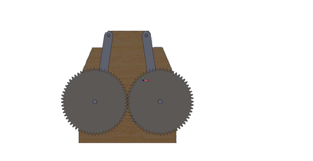 Fig No.3.2 Finalized drive train
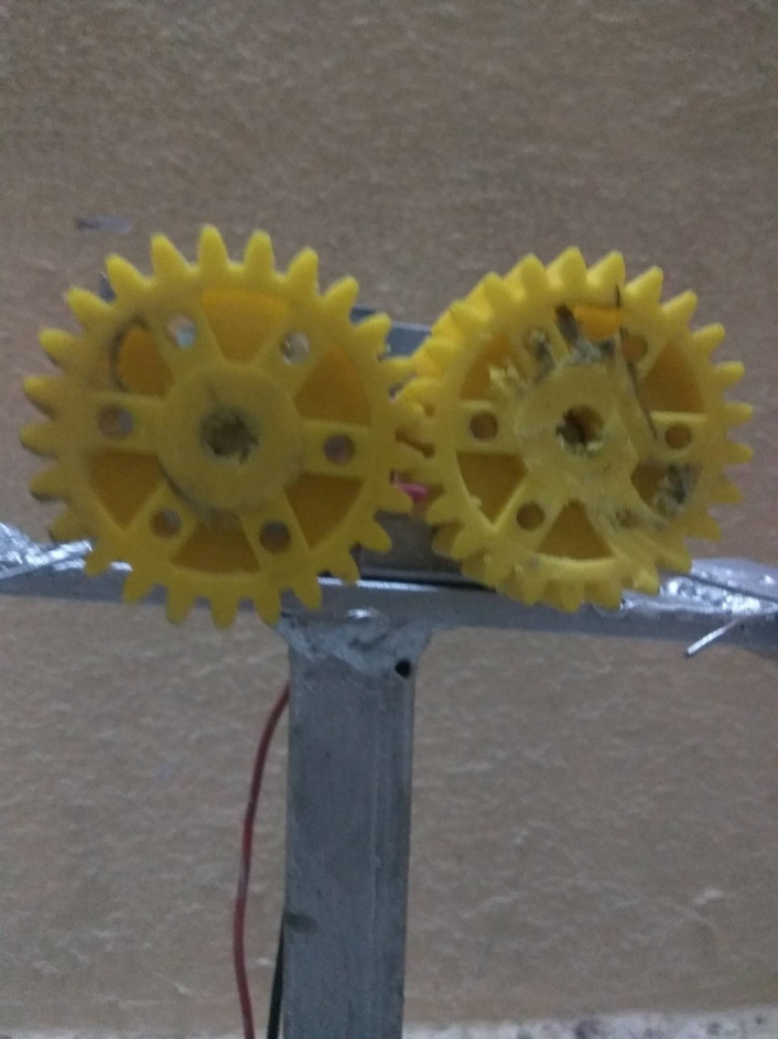 Fig No. 3.3 Real model (Drive Train)
3.5 Battery
The group has tried to consider the lithium ion battery but due to the budget in consideration lead acid battery is used to power the motor. Specifications of battery are 12V and 1.3Ah.It is a rechargeable sealed lead acid battery.
Fig No. 3.3 Real model (Drive Train)
3.5 Battery
The group has tried to consider the lithium ion battery but due to the budget in consideration lead acid battery is used to power the motor. Specifications of battery are 12V and 1.3Ah.It is a rechargeable sealed lead acid battery.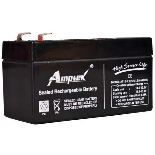 Fig No.3.4 Lead acid battery used
3.6 Motor
The group researched different types of motors and decided that a DC motor would be most appropriate for this project. 60RPM Centre Shaft Economy Series DC Motor is of high quality and low cost DC geared motor. It has steel gears and pinions to ensure longer life and better wear and tear properties. The gears are fixed on toughened steel shafts polished to a mirror finish. The output shaft rotates in a plastic bushing. The whole assembly is covered with a plastic ring. Gearbox is sealed and oiled with lithium grease and need no maintenance. The motor is screwed to the gear box from inside. Although motor gives 60 RPM at 12V but motor runs smoothly from 4V to 12V and gives wide range of RPM, and torque. Tables below gives fairly good idea of the motor’s performance in terms of RPM and no load current as a function of voltage and stall torque, stall current as a function of voltage.
Fig No.3.4 Lead acid battery used
3.6 Motor
The group researched different types of motors and decided that a DC motor would be most appropriate for this project. 60RPM Centre Shaft Economy Series DC Motor is of high quality and low cost DC geared motor. It has steel gears and pinions to ensure longer life and better wear and tear properties. The gears are fixed on toughened steel shafts polished to a mirror finish. The output shaft rotates in a plastic bushing. The whole assembly is covered with a plastic ring. Gearbox is sealed and oiled with lithium grease and need no maintenance. The motor is screwed to the gear box from inside. Although motor gives 60 RPM at 12V but motor runs smoothly from 4V to 12V and gives wide range of RPM, and torque. Tables below gives fairly good idea of the motor’s performance in terms of RPM and no load current as a function of voltage and stall torque, stall current as a function of voltage.
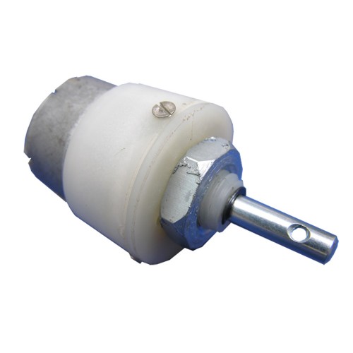 Fig No.3.5 DC motor
CHAPTER 4
4. MANUFACTURING
4.1 Wing Spars
The wing spars mounts are cut using the cutting tool in workshops. Then the mounts are welded to the frame. Wing spars of desirable lengths are cut using cutting wheel. The ends of the rods are welded with nuts on both ends. This is done for easy attachment of consecutive rods using screws.
Fig No.3.5 DC motor
CHAPTER 4
4. MANUFACTURING
4.1 Wing Spars
The wing spars mounts are cut using the cutting tool in workshops. Then the mounts are welded to the frame. Wing spars of desirable lengths are cut using cutting wheel. The ends of the rods are welded with nuts on both ends. This is done for easy attachment of consecutive rods using screws.
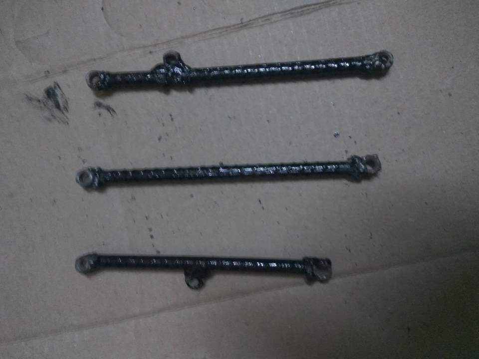 Fig No. 4.1 Wing spars
The body was designed so that it could be easily manufactured. . A sturdy design for the body was achieved to create a very solid base. Mild steel plates are used as the frame structure. The plates are welded together by arc welding process. The base of the frame is H shape in structure.
4.3 Arc welding
The group used arc welding to weld mild steel plates for the frame. The nuts are also fixed on the both the ends of the iron rods by welding process.
4.4 Final Assembly
After manufacturing the individual parts, assembly was rather straightforward. The hinge, gears, drive bars could all be fastened to the body with small metal brads. Bolts are very effective in attaching the spars to the hinge. A photograph of this assembly is shown below in Figure 4.2.
Fig No. 4.1 Wing spars
The body was designed so that it could be easily manufactured. . A sturdy design for the body was achieved to create a very solid base. Mild steel plates are used as the frame structure. The plates are welded together by arc welding process. The base of the frame is H shape in structure.
4.3 Arc welding
The group used arc welding to weld mild steel plates for the frame. The nuts are also fixed on the both the ends of the iron rods by welding process.
4.4 Final Assembly
After manufacturing the individual parts, assembly was rather straightforward. The hinge, gears, drive bars could all be fastened to the body with small metal brads. Bolts are very effective in attaching the spars to the hinge. A photograph of this assembly is shown below in Figure 4.2.
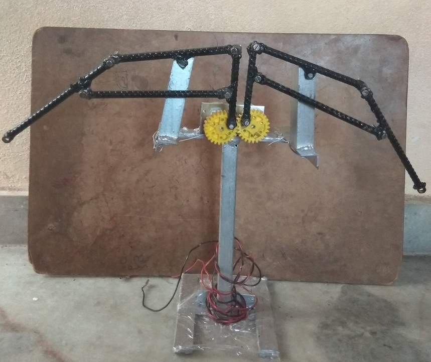 Fig No.4.2 Photograph of the complete assembly.
CHAPTER-5
CONCLUSIONS
In this project, we achieved control both wing mechanisms. The main task of this project make a surveillance robot. It gives adaptable operation of robot controller which does not modify the hardware. Further development of this system depends on the application we are using an area of work. The system can be added features like gas sensor, thermal image sensing, wireless control, connecting robotic arms and can be used in pick and place purposes etc… can be done. The development of this system has wide area of applications such as in Military and Law enforcement and Industrial and in Disaster management and so on. The design process detailed by this report began with an examination of the project objective. This is to build a flapping-wing. After a thorough literary review, it was decided that the wing movements of most birds and insects is very complex with twists and other motions that are not yet fully understood by experts. Because of this a two-wing design, utilizing the clap-and-fling effect, was selected. This allows for the design of a vehicle capable of flight with a simplified wing motion. These wings are attached to a symmetric hinge that is powered by a motor. A battery powers the motor, allowing for free flight with an onboard power source.
REFERENCES
Fig No.4.2 Photograph of the complete assembly.
CHAPTER-5
CONCLUSIONS
In this project, we achieved control both wing mechanisms. The main task of this project make a surveillance robot. It gives adaptable operation of robot controller which does not modify the hardware. Further development of this system depends on the application we are using an area of work. The system can be added features like gas sensor, thermal image sensing, wireless control, connecting robotic arms and can be used in pick and place purposes etc… can be done. The development of this system has wide area of applications such as in Military and Law enforcement and Industrial and in Disaster management and so on. The design process detailed by this report began with an examination of the project objective. This is to build a flapping-wing. After a thorough literary review, it was decided that the wing movements of most birds and insects is very complex with twists and other motions that are not yet fully understood by experts. Because of this a two-wing design, utilizing the clap-and-fling effect, was selected. This allows for the design of a vehicle capable of flight with a simplified wing motion. These wings are attached to a symmetric hinge that is powered by a motor. A battery powers the motor, allowing for free flight with an onboard power source.
REFERENCES
Fig No. 2.5 Harris model (Top view)
Fig No. 2.6 Three panel model
The wing's flapping indication is activated through the center panel's vertical oscillation & driven in simple harmonic motion by a mechanism. The middle panel is built to be rigid in bending and twisting, and includes a simple flat-bottom aerofoil (nominally, a Clark-Y). It was initially imagined that the center panel would require a direct pitch articulation in conjunction with its vertical (plunging) motion. As it was found pterosaur model. An ornithopter isn't essential to be a scale model of an animal, and the three panel wing thus provides an attractive means for power evening as well as active balance. The wing's flapping motion is triggered through the center panel's vertical oscillation. Driven in simple harmonic motion by a mechanism. The center panel is constructed to be rigid in bending and twisting, and incorporates a simple flat-bottom aero foil (nominally, a Clark-Y). It was originally envisaged that the center panel would require a direct pitch articulation in conjunction with its vertical (plunging) motion; but it was found, as described later, that it operated most effectively in plunging only. The external panels operate in a span wise- seesaw way and determined at one end by hinge connections to the center panel. There were two systems of support struts and hinges for the outer panels in the course of their evolution, from 1985 to 1987 the strut assembly was rigid, with a single hinge connection to the outer panel. The kinematic requirements were then met by means of span wise sliding hinges to the centre panel. That is, the driving hinges on the end of an outer panel had lubricated cylindrical extensions which slid, piston-like, into the center panel’s hollow spar tubes. This demonstrated to be a very consistent system, but it had the aerodynamic disadvantage of producing large, variable. Span wise gaps in the middle of the center and outer panels. Pieces of stretchable fabric were used to cover the gaps; but this, aerodynamically, was not a particularly efficient solution. In 1989, the support struts were changed to a system incorporating hinged vertical links. These allowed the sliding hinges at the centre panel to be replaced with simple non-sliding units. The gap then remained small and could be aerodynamically sealed with narrow abutting extension strips attached to the end faces of the panels. This system operated consistently during the development of the flight tests in 1989 and 1991. The external panels between 1985 and 1987 united a single-surface aerofoil and two spar assembly Attached to the ribs were short spanwise tubular pieces through which the spars accepted. The original idea was that since the single sur-face aerofoil has torsional compliance, the outer panel's pitching distribution could be driven by spanwisc rocking of the two spars. wolb JIM a WM AM;Met at Midi 4CCIIICU woe a ltddlMaLPIC (=Sign. Later, as it became obvious from flight tests and the developing analysis that the wing had extreme torsional compliance, the rear spar was extended and a portion of it changed to a 1/4 in diameter fibreglass rod. In fact, there was a flight test session where the rear spar was a 1/4 in diameter solid carbonfibre rod. Guided by the analysis, the ornithopter's performance improved steadily during this course of development. However, it was never near to achieving sustained flight. That is. The flight mode was a "powered glide", where the flapping would clearly extend the dis-tance flown compared with the non-flapping cases, but it would not climb or maintain altitude. The reason, revealed by windtunnel tests01), was that the actual aerodynamic characteristics fell short of the estimated values used as inputs in the analysis. In specific, the aerofoil had high chord-wise drag (Co = 0.063). Poor leading-edge suction en, = 0-29). It detached flow on one side or the other at all angles of outbreak. In comparison with modem double surface sections, this aerofoil was a very poor performer (typically, for a Reynolds number of 2 x 10³, a modem aerofoil should give Co= 0.012 and r1, 44 0.90). It was desired, however, to retain the single-surface feature because of its torsional compliance, and to find ways to improve such an aerofoil's aerodynamic performance.
2.6 Mechanism
A mechanism is a device intended to transform input forces and movement into an anticipated set of output forces and movement. Mechanisms generally has moving constituents such as gears, gear trains, belt, chain drives, cam and follower mechanisms, and linkages. Friction devices such as brakes, clutches and structural components such as the frame, bearings ,bfasteners, springs, lubricants and seals.
The German scientist delivers the explanation "a machine is an arrangement of resistant bodies so arranged that by their means the mechanical forces of nature can be compelled to do work attended by certain determinate motion." In this context, his use of machine is commonly understood to mean mechanism.
The combination of force and movement describes power, and a mechanism is intended to achieve power. In order to reach a wanted set of forces and movement.
A mechanism is usually a larger process or mechanical system. Sometimes a complete machine may be mentioned to as a mechanism. Examples are the steering mechanism in a car and the winding mechanism of a wristwatch. Multiple mechanisms are machines.
Types of Mechanisms
From the period of Archimedes mechanisms were well-thought-out to be constructed from simple machines, such as the lever, pulley, screw, wedge, wheel and inclined plane. It was Reuleaux who focused on bodies, called links, and the connections between these bodies called kinematic joints or pairs. In order to use geometry to study the drive of a mechanism, its links are modeled as inelastic bodies. This means distances in the middle of points in a link are assumed to be unaffected as the mechanism moves that is the link does not bend. Thus, the relative movement in the middle of points in two connected links is considered to result from the kinematic pair that joints them. Kinematic pairs are measured to provide ideal constraints in the middle of two links, such as the constraint of a single point for pure rotation. The constraint of a line for pure sliding, as well as pure rolling lacking slipping and point contact with slipping. A mechanism is modeled as an assembly of inelastic links and kinematic pairs.Kinematic pairs
Reuleaux stated the ideal connections in the mid of links kinematic pairs. He distinguished in the middle of higher pairs which were said to have line contact among the two links and lower pairs that have area contact amid the links. J. Phillips shows that there are many approaches to build pairs that do not fit this simple. A lower pair is a joint that has surface interaction amid the pair of elements. We have the following cases:- A revolute pair requires a line in the moving body to remain co-linear with a line in the fixed body, and a plane vertical to this line in the moving body maintains contact. It imposes five constraints on the relative movement of the links, which hence has one degree of freedom.
- A prismatic joint requires a line in a moving body remain co-linear with a line in the fixed body, and a plane similar to this line in moving body sustain contact with a alike parallel plane in the immovable body. This enforces five constraints on the relative movement of the links, which consequently has one degree of freedom.
- A cylindrical joint needs a line in the moving body to remain co-linear with a line in the fixed body. It is a blend of revolute joint and sliding joint. This joint has two degrees of freedom.
- A ball joint, desires that a point in the moving body keep connection with a point in the static body. This joint has three degrees of freedom.
- A planar joint needs that a plane in the moving body maintain contact with a plane in fixed body. This joint has three degrees of freedom.
- A helical joint has one degree of freedom since the rotational indications are related to the helix angle of the thread.
Planar mechanism
It is a mechanical system which is held in reserve so the paths of points in all the bodies of the method fib on planes parallel to the ground plane. The revolving axes of hinged joints that join the bodies in the system are perpendicular to this ground plane.Spherical mechanism
It is a mechanical system that the bodies change in a way that the paths of points in the system lie on concentric spheres. The rotating axes of hinged joints that associate the bodies in the system to pass through the center of these spheres.Spatial mechanism
It is a mechanical system which has at least one body that moves in a direction that its point trajectories are general space curves. The turning axes of hinged joints that connect the bodies in the system form lines in space that do not transect and have different joint normals.2.7 Gears and gear trains

- The ratio of pitch circles of coupling gears states the speed ratio and the mechanical use of the gear set.
- A planetary gear train provides high gear reduction in a compact package.
- It is possible to design gear teeth for gears that are not-circular, but still transmit torque smoothly.
- The speed ratio of chain and speed ratio of belt drive is calculated in the same way as gear ratios. See bicycle gearing.
History of the differential gear
The earliest gears was Chinese actual examples of wheels and moulds for wheels dating from the 4th century B.C. which have been preserved. It might be remarked that these "machine" gear wheels are characterized by having a "round number" of teeth and a shank with a square hole which fits without turning on a squared shaft.[3] The earliest gears in Europe was circa A.D. 50 but they can be drawn back to the Greek mechanics of the Alexandrian school in the 3rd century BCE and were greatly settled by the Greek polymath Archimedes (287–212 BCE). The Antikythera mechanism is a model of a very early and complex geared device, designed to compute astronomical positions. Its time of building is projected between 150 and 100 BC. Fig No. 2.8 Gear engage
The velocity ratio that teeth give gears offers a benefit over other drives (such as traction drives and V-belts) in exactness machines like watches that depend on an exact velocity ratio. Some cases where driver and follower are proximal, gears also have an advantage over other drives in reduced number of parts required. The gears are more expensive to manufacture and their lubrication requirements may execute a higher operating cost.
Fig No. 2.8 Gear engage
The velocity ratio that teeth give gears offers a benefit over other drives (such as traction drives and V-belts) in exactness machines like watches that depend on an exact velocity ratio. Some cases where driver and follower are proximal, gears also have an advantage over other drives in reduced number of parts required. The gears are more expensive to manufacture and their lubrication requirements may execute a higher operating cost.
General nomenclature
 Fig No. 2.9 Gear terminology
- Rotational frequency, n:
- Angular frequency, ω:
Rad/second
- Number of teeth, N:
- Gear, wheel:
- Pinion:
- Path of contact:
- Line of action, pressure line:
- Axis:
- Pitch point:
- Pitch circle, pitch line:
- Pitch diameter, d:
in metric units or
in imperial units.
- Module or modulus, m:
Where, m is the module and p the circular pitch. The units of module are millimeters; Module is sometimes used with the units of inches. When the diametral pitch, DP.
in conventional metric units.
The distance between the two axis becomes
where a is the axis distance, z1 and z2 are the number of components (teeth) for each of the two wheels (gears). These numbers are often chosen among peaks to create an even contact between every cog of both wheels, and in so doing avoid unnecessary wear and damage. An identical gear wear is obtained by approving the number of teeth of the two gears meshing together are relatively key to each other. This occurs when the greatest common divisor (GCD) of each gear tooth count matches 1, e.g. GCD(16,25)=1; If a 1:1 gear ratio is sought after a relatively prime gear may be put in between the two gears; this maintains the 1:1 ratio but reverses the gear direction. A second relatively prime gear could also be inserted to return the original rotational direction while keeping uniform wear with all 4 gears in this case. Mechanical engineers at least in continental Europe use the module instead of circular pitch. The module, just like the circular pitch, can be used for all types of cogs, not just evolving based straight cog.
Cam and follower mechanisms
A cam and a follower is molded by the direct contact of two permanent shaped links. The driving link is called the cam and the link that is driven by the direct contact of the surface of both links is called the follower. The form of the mating surfaces of the cam and follower controls the motion of the mechanism. Generally a cam and follower mechanism's energy is conveyed from cam to follower. The cam shaft is rotated according to the cam profile while the follower moves up and down. Diverse types of eccentric cam followers are also available in which energy is conveyed from the follower to the cam. The main advantage of this type of cam follower mechanism is that the follower moves a tiny bit and helps to rotate the cam 6 times extra circumference span with 70% force.2.8 Linkages
A linkage is a collection of links connected by joints. The links are the structural elements and the joints let motion. The single most useful example is the planar four-bar linkage. Though, there are many more special linkages:- Watt's linkage is a four-bar linkage that generates a rough straight line. It was serious to the operation of his design for the steam engine. This linkage acts in vehicle suspensions to prevent side movement of the body comparative to the wheels.
- The achievement of Watt's linkage leads to the design of similar straight-line linkages.
- The Peaucellier linkage produces a true straight-line output from a rotary input.
- The Sarrus linkage is a spatial linkage that generates straight-line movement from a rotary input.
- Jansen’s linkage and the Klann’s linkage are new inventions that deliver stimulating walking actions. They are individually a six-bar and an eight-bar linkage.
Flexure mechanisms
A flexure mechanism contains a series of inelastic bodies connected by accommodating elements that is designed to produce a geometrically well-defined motion upon claim of a force. Linkage Mechanism Have you ever wondered what kind of mechanisms causes the wind shield wiper on the front widow of car to oscillate. The mechanism, shown in Figure, transforms the rotary motion of the motor into an oscillating motion of the windshield wiper.
Fig No.2.10 Windshield wiper
The four bar linkage is the simplest and the most useful mechanism. As we mentioned before, a mechanism composed of rigid bodies and lower pair is called a linkage . In planar mechanisms, there are two kinds of lower pair’s prismatic and revolute pairs.
The simplest closed loop linkage is the four bar linkage which has four members, 3 moving links, one fixed link and four pin joints. A linkage that has at least one fixed link is known as mechanism. The following example of a four bar linkage was formed in SimDesign.
Fig No. 2.11 Four bar linkage in SimDesign
This mechanism has three moving links. Two of the links are restrained to the frame which is not shown in this image. In SimDesign, links can be nailed to the background thereby making them into the frame.
How many DOF does this mechanism have? If we need it to have just unique, we can enact one constraint on the linkage and it will have a fixed motion. The four bar linkage is the simplest and the most useful mechanism.
A mechanism is composed of inelastic bodies and lower pairs called linkages. In planar mechanisms there are only two kinds of lower pairs: turning pairs and prismatic pairs.
Functions of Linkages
The purpose of a link mechanism is to produce oscillating, rotating or reciprocating motion from the rotation of a crank or vice versa. Stated more specifically linkages may be used to convert:
- Continuous, with a constant or variable angular velocity ratio. rotation into continuous rotation
- Continuous rotation into oscillation or reciprocation (or the reverse), with a constant or variable velocity ratio.
- Oscillation, reciprocation with a constant or variable velocity ratio.
- Function generation: The relative motion in the middle of the links connected to the frame.
- Path generation: The track of a tracer point.
- Motion generation: The motion of the coupler linkage.
- The four-bar linkage mechanism, and
- The slider-crank mechanism.
- Crank: An adjacent link which revolves relative to the frame.
- Rocker: Any link which does not revolve.
- Crank-rocker mechanism: In a four bar linkage where shorter side link revolves and the other one oscillates.
- Double-crank mechanism: In a four bar linkage where both of the side links revolve.
- Double-rocker mechanism: In a four bar linkage if both side links rock.
- s = length of shortest bar
- l = length of longest bar
- p, q = lengths of intermediate bar
- When the smallest link is a side link then the mechanism is a crank-rocker mechanism. The smallest link is the crank in the mechanism.
- When the smallest link is the frame of the mechanism then the mechanism is a double-crank mechanism.
- When the shortest link is the coupler link, the mechanism is a double-rocker mechanism.
Fig No. 2.12 DC Motor
The rotor is placed within the force field caused by 2 permanent magnets. By pertaining to things, each side of the wire loop can have a force on them. attempting to create the wire loop rotate. this is applied to the loop through the commentator, that is shown as 2 items of metal shaped into a hoop within the figure. Current is applied to the commentator by stationary C blocks, known as brushes, that rub against the commentator ring. The loop can still rotate anticlockwise till it's vertical. At now, the stationary brushes can apply current round the loop nomore as a result of they're going to be to bear with the gap between the commentator segments, however the inertia of the loop keeps it going very little additional, till the DC provide reconnects to the commentator segments, and therefore the current then goes round the loop within the wrong way. The force although remains within the same direction and therefore the loop continues to rotate.
Fig No.2.13: The Operation of DC Motor
2.9.1 DC Motor Voltage
DC motors ar non-polarized - which means that one will reverse voltage with none dangerous things happening. Typical DC motors ar rated from concerning 6V-12V. The larger ones ar typically 24V or additional. Except for the needs of this project, do keep within the 6V-12V vary. It’s expressed that voltage is directly associated with motor torsion. High voltage produces higher torsion. A DC motor is rated at the voltage wherever it's most effective at running. If only a few volts ar applied, it simply will not work. If an excessive amount of is applied, can|it'll} overheat and also the coils will soften. Therefore the general rule is to use as near the rated voltage of the motor. However don’t exceed 12V motors unless torsion is crucial badly.
2.9.2 DC Motor Current
As with all electronic equipment, one should listen to current. Too little, and it simply will not work. Too much, the motor can meltdown. Once shopping for a motor, there ar 2 current ratings one ought to listen to. The primary is working current. this is often the typical quantity of current the motor is anticipated to draw beneath a typical force. Multiply this range by the valued voltage and also the average power draw necessary to run the motor is obtained. The opposite current rating that one must listen to is that the stall current. This is often once the motor is power up, and enough force is place to force it to prevent rotating. This is often the utmost quantity of current the motor can ever draw, and therefore the utmost quantity of power too. So, one should style all management electronic equipment capable of handling this stall current. Also, if the motor is continually run, or run it over the rated voltage, it's knowing sink to stay the motor's coils from melting.
2.9.3 DC Motor Power Rating
All motors are rated at definite wattage. Wattage is energy and incompetence of energy conversion is directly connected to heat output. Too much heat, the motor coils melt. So the manufacturers of motors know how much wattage will cause motor failure, and post this on the motor specification sheets. The equation is:
Power (watts) = Voltage * Current
Increase voltage and extent current until the power is about -90% below the given power rating.
2.9.10 DC Motor Torque
Torque is well-defined as that force which inclines to harvest and maintain rotation. The purpose of torque in a DC motor is to provide the mechanical output or effort the piece of apparatus that the DC motor is committed to. There are two torque value ratings which must been pay attention to. The first is the operating torque. This is the torque the motor is calculated to give. Usually it is the listed torque value. The other rated value is stall torque. This is the torque required to stop the motor from rotating. The torque developed by the motor can be determined using Equation:
T = KQI,
Where
T = torque
K = a constant depending on physical size of motor
Q = field flux, number of lines of force per pole
I = armature current
To buy a DC motor, there will be two torque value ratings to which attention must be paid. The first is operating torque. This is the torque the motor is considered to give. Usually it is the listed torque value. The other rated value is stall torque. This is the torque necessary to stop the motor to rotate. If one need a little more speed, going 20% above the rated motor voltage value is fairly safe. But, that this is less efficient, and the motor should be heat- sinked.
Velocity Velocity is very complex when it comes to DC motors. The general rule is motors run the most efficient when run at the highest possible speeds. Obviously however this is not possible. There are times to run the motor slowly. Just like car, it won't to keep the car constantly at high speed. The voltage and applied torque resistance clearly affects speed.
PMDC motor:
This motor using for this project PMDC motor In a dc motor, an armature rotates inside a magnetic field. The working principle of DC motor is based on the point that whenever a current carrying conductor is placed inside magnetic, there will be mechanical force experienced by that conductor. All kinds of DC work in this principle only. Therefore for constructing a dc motor it is necessary to establish a magnetic field. The magnetic field is obviously established by means of magnet. The magnet can by any types i.e. it may be electromagnet or it may be a permanent magnet. When permanent magnet is used to create magnetic field in a DC motor, the motor is referred as permanent magnet dc motor or PMDC motor. Did you ever uncover any battery operated toy, if you had uncovered, you had obviously found a battery-operated motor inside it. This battery operated motor is nothing but a permanent magnet dc motor or PMDC motor. These types of motors are basically simple in construction. These motors are commonly used as starter motor in automobiles, windshield wipers, washer, for blowers used in heaters and air conditioners, to raise and lower windows, it also extensively used in toys. As the magnetic field strength of a permanent magnet is fixed it cannot be organized externally, field control of this type of dc motor cannot be possible. Thus permanent magnet dc motor is used where there is no need of speed control of motor by means of controlling its field. Minor fractional and substitute fractional kW motors are now constructed with permanent magnet.
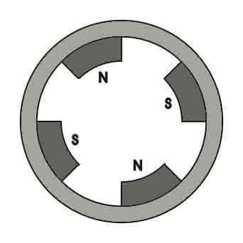
Working Principle of Permanent Magnet DC Motor or PMDC Motor
As we said earlier the working principle of PMDC motor is just similar to the general working. That is when a carrying conductor comes inside a magnetic field, a mechanical force will be experienced by the conductor and the direction of this force is governed by Fleming’s left hand rule. Like in a permanent magnet dc motor, the armature is placed inside the magnetic field of permanent magnet; the armature is rotated in the direction of the generated force. Here each conductor of the armature experiences the mechanical force F = B.I.L Newton where B is the magnetic field strength in Tesla (weber / m2), I is the current in Ampere flowing through that conductor and L is length of the conductor in metre comes under the magnetic field. Each conductor of the armature experiences a force and the compilation of those forces produces a torque, which tends to rotate the armature.
Fig No. 2.15 Equivalent Circuit of Permanent Magnet DC Motor or PMDC Motor
As in PMDC motor the field is produced by permanent magnet, there is no need of drawing field coils in the equivalent circuit of permanent magnet dc motor. The supply voltage to the armature may have armature resistance drop and rest of the supply voltage is opposed by back emf of the motor. Hence voltage equation of the motor is given by,
I, is armature current and R is armature resistance of the motor.
Eb is the back emf and V is the supply voltage.
Benefits of Permanent Magnet DC Motor or PMDC Motor
PMDC motor has some advantages over other types of dc motors. They are:
- No need of field excitation arrangement.
- No input power in consumed for excitation which improves efficiency of dc motor.
- No field coil hence space for field coil is saved which reduces the overall size of the motor.
- Cheaper and economical for fractional kW rated applications.
Disadvantages of Permanent Magnet DC Motor or PMDC Motor
- In this situation, the armature reaction of DC motor may not be compensated so the magnetic strength of the field can become weak due to the demagnetizing outcome of armature reaction.
- There is also a chance of getting the poles permanently demagnetized (partial) due to excessive armature current during starting, reversal and overloading condition of the motor.
- Another key drawback of PMDC motor is that, the field in the air gap is fixed and limited and it cannot be controlled externally. Therefore, very efficient speed control of DC motor in this type of motor is difficult.
Applications of Permanent Magnet DC Motor or PMDC Motor
PMDC motor is extensively used where small dc motors are required and also very effective control is not required, such as in automobiles starter, toys, wipers, washers, hot blowers, air conditioners, computer disc drives and in many more. 2.10 WELDING Arc welding Arc welding is a process which is used to join metal and metal by using electricity to create adequate heat to melt metal, and the melted metals when cool result in a binding of the metals. It is a type of welding that uses a welding power supply to create an electric arc between an electrode and the base material to melt the metals at the welding point. They can be used as either direct (DC) or alternating (AC) current, and consumable or non-consumable electrodes. The welding region is usually protected by some type of shielding gas, vapor, or slag. Arc welding processes can be manual, semi-automatic, or fully automated. First developed in the late part of the 19th century, arc welding became commercially important in shipbuilding during the Second World War. Today it remains as an vital process for the assembly of steel structures and vehicles. To supply the electrical energy necessary for arc welding processes, a number of different power supplies can be used. The most common grouping is constant current power supplies and constant voltage power supplies. In arc welding, the voltage is directly related to the length of the arc, and the current is related to the amount of heat input. Constant current supply is broadly used in manual welding processes like gas tungsten arc welding and shielded metal arc welding, because they maintain a relatively constant current even as the voltage varies. This is important because in manual welding, it can be difficult to hold the electrode perfectly steady, and as a result, the arc length and thus voltage tend to fluctuate. Constant voltage power supply keep the voltage constant and vary the current, and as a result, are mostly used for automated welding processes such as gas metal arc welding, flux cored arc welding, and submerged arc welding. In this process arc length is kept constant, so that any fluctuation in the distance between the wire and the base material is quickly resolved by a huge change in current. In case, if the wire and the base material get very close, the current rapidly increases and in turn causes the heat to increase and the tip of the wire melts and returns to its original separation distance. The direction of current used in arc welding plays a significant role in welding. Consumable electrode processes like shielded metal arc welding and gas metal arc welding regularly use direct current, but the electrode can be charged either positively or negatively. In welding, the positively charged anode has a larger heat concentration (around 60%) and, as a result, changing the polarity of the electrode affects weld properties. If the electrode is positively charged, it melts quickly, increasing weld penetration and welding speed. Alternatively, a negatively charged electrode results in thin welds. Non-consumable electrode processes, like gas tungsten arc welding, can use any type of direct current (DC), as well as alternating current (AC). However with direct current the electrode only creates the arc and does not provide filler material, a positively charged electrode causes shallow welds, while a negatively charged electrode makes deeper welds. Alternating current rapidly moves between these two, which results in medium-penetration welds. One disadvantage of AC, a fact that the arc requirement be re-ignited after every zero crossing, has been addressed with the invention of special power units that produce a square wave method instead of the normal sine wave, removing low-voltage time after the zero crossings and minimizing the effects of the problem.
Fig No. 2.16 Arc welding
Duty cycle is a welding apparatus specification which explains the number of minutes, within a 10-minute period, during which a given arc welder can safely be used. For example, an 80A welder with a 60% duty cycle must be "rested" for at least 4 minutes after 6 minutes of nonstop welding. Failure to spot duty cycle confines could damage the welder. Commercial and professional-grade welders normally have a 100% duty cycle.
CHAPTER 3
DESIGN AND SELECTION OF PARTS
The group reviewed through the literature to gain insight into the motion of flapping wings and how they generate lift. Previous projects involving flapping wing MAVs inspired the group.
The modeling process began with a basic idea of what the group was hoping to achieve with this project – a relatively small flapping wing vehicle capable of vertical takeoff and landing, hover, and horizontal flight. Through research, that it was decided that mimicking a two-wing bird or insect would be rather difficult and unreasonable, for these animals move in a very complex manner. Through more research and the discovery of the clap-and-fling method of flight, the group decided upon a two-wing. This is easier to model and manufacture compared to the motion required for a two-wing vehicle to take flight.
As the group continued to model the wings, the next step was to choose which components and materials would be used in the design. In the development of the body, and wings, the group researched materials that were lightweight, yet durable enough to withstand impact and rapid movement. The group also researched materials that could be manufactured to conserve the financial budget. Also involved in the design are several electronic components: a battery and a motor. These components must power the flapping the wings. Detailed descriptions of these components and their purpose, as well as why the group chose each specific item, will be included in this section.
Fig No.3.1 Isometric View of the Model
3.1 Body
The group finally constricted the field to two different materials. The first wood and the second iron rods. The wood was used but it failed to maintain its shape due to the vibrations. Thus wood failed to maintain its perfect frame dimensions when drivetrain is fixed. Then mild steel plates are used to make the frame which maintained its shape. The shape of the frame was designed to be simple. There is another section designed to mount the drive train and hinge. The frame is made of mild steel bars. The frame shape was finalized for ease of manufacturing and for simplicity as well. The finalized drive train was used to design the front part of the frame and a very basic final design was chosen.
3.2 Wings
For a design involving two wings, it is crucial for each wing to mimic the motion of bird. For this purpose, the group decided to research thin plastic films to comprise the wing, and iron rod spars to provide support and allow for the clap and fling effect.
While researching different wing shapes, the grouptried to research different wings of various birds and tried to understand its movement and concluded that spars to bend closer to the leading edge and preventing the behind corners of the wings from being unsteady during flapping.
To finalize the size of the wings, the group used a lift equation found through texts. This equation is an assessed equation derived through testing of rectangular flapping wings.
After finalizing the size and shape of the wings, the group researched materials to form the spars and membrane. These materials need not to be as light in weight but strong enough to flap without failing.
Taking these demanding applications into account, the group researched common durable materials such as iron rods, wood and plastic. All three materials would be strong enough to support the wings, but the group chose iron rods, the strongest of the three. Iron rods can be cut and welded easily whereas the wood was not strong enough as the cracks appear due to machining operations. Iron rods are comparatively higher in price; however, after reviewing the budget, the group decided that it would be worth it is for its strength and reliability. Once we selected iron rods as the spar material, it was time to focus on a membrane that could be effectively attached to it. And the group decided to use plastic boards as the membrane.
3.3 Hinge
A hinge is necessary to hold the two 0ings together and allow a flapping motion that brings the leading edges together. The group selected mild steel bars as a material. This would withstand the rapid movement without failure.
This simpler hinge was attached to the frame by welding.
3.4 Drive Train
The motion of the hinge will be created by a drive train connected to the motor. The group considered two different drive train options. The first contained gears that wouldspin parallel to the axis of forward movement (with their axels perpendicular). Although this design was successfullyemployed onto previous MAVs, it was dismissed due its complicated drive train and the effect that gyroscopic forces would have on flight.
Instead, the group chose a method involving two counter-rotating gears, spinning perpendicular to the forward movement of the MAV (with their axels parallel). Mechanically, this design is more simple and easier to construct, and due to the counter-rotation, the gyroscopic forces would be minimized.
From our motor tests we discovered that a drive train ratio of 1:1 would be desirable, and we ordered gears to match this design. This would give us an acceptable drive train assembly, and this drive train can be seen in Figure. This drive train is simplistic and secure, so we are anticipating minimal issues with its assembly.
For the design of the drive bar and some other design parameters, we used SolidWorks to create and test the kinematics of the drive train. This process can be seen in Figure
Fig No.3.2 Finalized drive train
Fig No. 3.3 Real model (Drive Train)
3.5 Battery
The group has tried to consider the lithium ion battery but due to the budget in consideration lead acid battery is used to power the motor. Specifications of battery are 12V and 1.3Ah.It is a rechargeable sealed lead acid battery.
Fig No.3.4 Lead acid battery used
3.6 Motor
The group researched different types of motors and decided that a DC motor would be most appropriate for this project. 60RPM Centre Shaft Economy Series DC Motor is of high quality and low cost DC geared motor. It has steel gears and pinions to ensure longer life and better wear and tear properties. The gears are fixed on toughened steel shafts polished to a mirror finish. The output shaft rotates in a plastic bushing. The whole assembly is covered with a plastic ring. Gearbox is sealed and oiled with lithium grease and need no maintenance. The motor is screwed to the gear box from inside. Although motor gives 60 RPM at 12V but motor runs smoothly from 4V to 12V and gives wide range of RPM, and torque. Tables below gives fairly good idea of the motor’s performance in terms of RPM and no load current as a function of voltage and stall torque, stall current as a function of voltage.
Fig No.3.5 DC motor
CHAPTER 4
4. MANUFACTURING
4.1 Wing Spars
The wing spars mounts are cut using the cutting tool in workshops. Then the mounts are welded to the frame. Wing spars of desirable lengths are cut using cutting wheel. The ends of the rods are welded with nuts on both ends. This is done for easy attachment of consecutive rods using screws.
Fig No. 4.1 Wing spars
The body was designed so that it could be easily manufactured. . A sturdy design for the body was achieved to create a very solid base. Mild steel plates are used as the frame structure. The plates are welded together by arc welding process. The base of the frame is H shape in structure.
4.3 Arc welding
The group used arc welding to weld mild steel plates for the frame. The nuts are also fixed on the both the ends of the iron rods by welding process.
4.4 Final Assembly
After manufacturing the individual parts, assembly was rather straightforward. The hinge, gears, drive bars could all be fastened to the body with small metal brads. Bolts are very effective in attaching the spars to the hinge. A photograph of this assembly is shown below in Figure 4.2.
Fig No.4.2 Photograph of the complete assembly.
CHAPTER-5
CONCLUSIONS
In this project, we achieved control both wing mechanisms. The main task of this project make a surveillance robot. It gives adaptable operation of robot controller which does not modify the hardware. Further development of this system depends on the application we are using an area of work. The system can be added features like gas sensor, thermal image sensing, wireless control, connecting robotic arms and can be used in pick and place purposes etc… can be done. The development of this system has wide area of applications such as in Military and Law enforcement and Industrial and in Disaster management and so on. The design process detailed by this report began with an examination of the project objective. This is to build a flapping-wing. After a thorough literary review, it was decided that the wing movements of most birds and insects is very complex with twists and other motions that are not yet fully understood by experts. Because of this a two-wing design, utilizing the clap-and-fling effect, was selected. This allows for the design of a vehicle capable of flight with a simplified wing motion. These wings are attached to a symmetric hinge that is powered by a motor. A battery powers the motor, allowing for free flight with an onboard power source.
REFERENCES
- Agrawal, S. K., Madangopal, R., & Khan, Z. A. (2004). Biologically inspired design of small flapping wing air vehicles using four-bar mechanisms and quasi-steady aerodynamics. Journal of Mechanical Design, , 1-8.
- Bruggeman, B. (2010). Improving flight performance of DelFly II in hover by improving wing design and driving mechanism. Delft University of Technology M.Sc.Thesis,
- De Croon, G., De Clercq, K., Ruijsink, R., Remes, B., & De Wagter, C. (2009). Design, aerodynamics, and vision-based control of the DelFly. International Journal of Micro Air Vehicles, 1(2), 71-97.
- GAJBHIYE, S., UPADHYAY, S., & HARSHA, S. (2012). FREE VIBRATION ANALYSIS OF FLAT THIN MEMBRANE. International Journal of Engineering Science, 4
- Groen, M. (2010). PIV and force measurements on the flapping-wing MAV DelFly II. Delft University of Technology M.Sc.Thesis,
- Hara, N., Tanaka, K., Ohtake, H., & Wang, H. O. (2009). Development of a flying robot with a pantograph-based variable wing mechanism. Robotics, IEEE Transactions on, 25(1), 79-87.
- Harmon, R. L. (2008). Aerodynamic modeling of a flapping membrane wing using motion tracking experiments ProQuest.
- Krashanitsa, R. Y., Silin, D., Shkarayev, S. V., & Abate, G. (2009). Flight dynamics of a flapping-wing air vehicle. International Journal of Micro Air Vehicles, 1(1), 35-49.
- Maxworthy, T. (1981). The fluid dynamics of insect flight. Annual Review of Fluid Mechanics, 13(1), 329-350.
- Michelson, R. C. (2004). Novel approaches to miniature flight platforms. Proceedings of the Institution of Mechanical Engineers, Part G: Journal of Aerospace Engineering, 218(6), 363-373. 29
- Miller, L. A., & Peskin, C. S. (2005). A computational fluid dynamics ofclap and fling'in the smallest insects. Journal of Experimental Biology, 208(2), 195-212.
- Mueller, D., Bruck, H., & Gupta, S. (2010). Measurement of thrust and lift forces associated with drag of compliant flapping wing for micro air vehicles using a new test stand design. Experimental Mechanics, 50(6), 725-735.
- Pornsin-Sirirak, T. N., Lee, S., Nassef, H., Grasmeyer, J., Tai, Y., Ho, C., & Keennon, M. (2000). MEMS wing technology for a battery-powered ornithopter. Paper presented at the Micro Electro Mechanical Systems, 2000. MEMS 2000. the Thirteenth Annual International Conference on, 799-804.
- Sane, S. P. (2003). The aerodynamics of insect flight. The Journal of Experimental Biology, 206(23), 4191-4208.
- Shyy, W., Aono, H., Chimakurthi, S., Trizila, P., Kang, C. K., Cesnik, C., & Liu, H. (2010). Recent progress in flapping wing aerodynamics and aeroelasticity. Progress in Aerospace Sciences, 46(7), 284-327.
- Taylor, G. K. (2001). Mechanics and aerodynamics of insect flight control. Biological Reviews, 76(4), 449-471.
- Whitney, J., & Wood, R. (2012). Conceptual design of flapping-wing micro air vehicles. Bioinspiration & Biomimetics, 7(3), 036001.
Cite This Work
To export a reference to this article please select a referencing stye below:
Reference Copied to Clipboard.
Reference Copied to Clipboard.
Reference Copied to Clipboard.
Reference Copied to Clipboard.
Reference Copied to Clipboard.
Reference Copied to Clipboard.
Reference Copied to Clipboard.
Related Services
View all


Related Content
All TagsContent relating to: "Animal Sciences"
Animal science can be described as studying the biochemistry, physiology, and behaviour of animals that are under human control. Historically, animal science degrees were known as animal husbandry and focused on livestock. Studies now include companion animals such as cats and dogs.
Related Articles

DMCA / Removal Request
If you are the original writer of this dissertation and no longer wish to have your work published on the UKDiss.com website then please: