Microcontroller Based Fingerprint Recognition Method for Indian Voting System
Info: 8653 words (35 pages) Dissertation
Published: 11th Dec 2019
Table of Contents
| TITLE
|
PAGE NO. |
| CHAPTER – 1: INTRODUCTION | 1 |
| 1.1 Introduction to electoral system in India. | 1 |
| 1.2 Motivation | 2 |
| 1.3 Current election scenario.
1.3.1 Pre-election duties. 1.3.2 Election day duties. 1.3.3 Post-Election duties. 1.4 Objective 1.5 Scope |
2
3 3 3 4 4 |
| CHAPTER-2: INTRODUCTION TO MODULES USED.
2.1 Introduction to Arduino. 2.1.1 Why Arduino? 2.1.2 Specifications. 2.2 How a Finger Print Module Works? 2.2.1 Features 2.3 Introduction to LCD. 2.3.1 Pin Description. 2.3.2 Features CHAPTER – 3 : DEVELOPMENTS ACCOMPLISHED 3.1 Study of block diagram 3.2 Hardware and software requirements 3.2.1 Hardware requirements. 3.2.2 Software requirements. 3.3 Working description of Arduino Uno. 3.3.1 Introduction 3.3.2 List of On-board Peripherals. 3.3.3 The Microcontroller 3.3.4 Pin configuration of Arduino Uno. 3.4 Working description of proposed algorithm. 3.4.1 Interfacing LCD with the Arduino Uno. 3.4.2 Interfacing fingerprint module with the Arduino Uno. 3.5 Study of flow chart 3.5.1 Flow chart 3.5.2 Flow chart description. CHAPTER – 4: RESULTS AND CONCLUSION 4.1 Results. 4.2 Conclusion. 4.3 Future Scope.
APPENDIX-A APPENDIX-B APPENDIX-C APPENDIX-D REFERENCES |
5
5 5 6 7 9 9 11 12 13 13 15 15 15 15 15 16 17 20 21 21 22 23 23 24 25 25 27 27 28 28 29 32 38 |
|
|
|
LIST OF FIGURES
| S.No | No. | Figure Name |
Page Number |
| 1 | 2.1 | Fingerprint Module | 7 |
| 2 | 2.2 | Fingerprint Module Connections | 8 |
| 3 | 2.3 | LCD Display Module | 10 |
| 4 | 3.1 | Block Diagram | 13 |
| 5 | 3.2 | Microcontroller AT328P-Pin Diagram | 17 |
| 6 | 3.3 | Arduino Pin Mapping | 19 |
| 7 | 3.4. | Arduino Pin Configuration | 20 |
| 8 | 3.5 | Interfacing LCD with Arduino | 21 |
| 9 | 3.6 | Interfacing Fingerprint Module with Arduino | 22 |
| 10 | 3.7 | Flowchart | 23 |
LIST OF TABLES
| S.No | No. | Table Name | Page
Number |
| 1 | 2.1 | Specification of Arduino | 6 |
| 2 | 2.2 | Pin Configuration of LCD module | 11 |
| 3 | 3.1 | On-Board Peripherals of Arduino | 16 |
ABSTRACT
A biometric system is essentially a pattern recognition system that works by acquiring biometric data from every individual, extracting a feature set of templates from the acquired data of templates, and comparing this template set against the set in the database. Verification mode of the fingerprint module verifies the set of acquired fingerprints with the existing. while, Identification mode finds the given fingerprint in the database. Indian government has the fingerprint and retina database of all the citizens of the country in the name of AADHAR. By making use of that database effectively with the help of Microcontroller, the problem of bogus voting can be completely eliminated. This project focuses on solving the said problem with the help of combination of biometric finger print and Microcontroller.
Fingerprint Based Secured Voting Machine is basically an embedded system. The user, who wants to poll his vote, has to punch his finger in the finger print scanner at the counter of the polling booth. Based on finger print identity of user, verification can be done by using the database of UIDAI (Unique Identification Authority of India).After Successful verification, the user will be allowed to pass through the voting section of the polling booth.
This project converges its broad line into a shorter one because of its accessibility restrictions of the government database. The Proposed work involves the storing of the fingerprints of few individuals in a separate module, which serves as a database (virtually). This unit helps us in verification process. And, further it allows the person to vote for a particular candidate. The votes will be stored in a separate module and used for counting process.
This method can be implemented in the near future because of its high dependency in Internet connectivity. Being a developing nation, India is emerging to a point where it can provide internet to remote places and small villages. It may take few years for this project to get implemented practically.
CHAPTER 1
INTRODUCTION
- Introduction to Electoral system in India
The Election scenario in India seems to be a hefty process. Lot of works were involved in conducting a successful election. During election days transport system gets totally interrupted and maximum surface transport and goods vehicles are taken off the road for the purpose of election duties. Government Colleges and School staffs suffer a lot in conducting the election works. Officers and staff from public sector will be allotted with the election duties.
As a result the public sector units have to face a complete closure of daily proceeding and the employees, customers related to it will face a huge interruption from their activities. Schools, colleges and institutions are taken as polling booths or Distribution Centre with Receiving Centers (DCRC) for distribution and collection of voting equipment’s namely electronic voting machine (EVM), and related documents to the polling officers.
The Government school students face a huge trouble as it disturbs their classes for a couple of days. For these, purposes a system is highly necessary that reduces these complex functionalities of the government. The proposed system makes use of the modern technology and should be injected with high security and it should be highly efficient. However, overcoming the above mentioned problems cannot be achieved on its full. It can be reduced to a certain extent that these election processes can be completed within two days of efficient working such that, the negative effects faced by the public during the course of elections will be reduced.
1.2 Motivation
The current Indian voting system makes use of the Electronic Voting Machine (EVM). This system has its advantages over the previously used Ballot paper voting system. However, the probability of error happening with the EVM is still high. The new system should be proposed that can eliminate the current difficulties of the EVM. High election duties and fake voting are the major drawbacks of the current system. These drawbacks may highly affect the results of the election. These scenarios formed the major motivation to move further into a new system.
- Current election scenario
The current voting system in India makes use of the electronic voting machine (EVM).The pre-election and post-election duties were completely done manually. No works were automated and this is the main reason behind the delays. The Election duties were basically divided into three.
- Pre-election Duties.
- Election Day Duties.
- Post-Election Duties
1.3.1 Pre-Election Duties
The election Duties involves the collection of individual details from the municipality and checking the presence of the individuals in their respective. For this purpose, Government school teachers were allotted to work in the verification process. This will disturb their daily routine of teaching the students. After the completion of the verification process the details will be directed to the election commission to calculate the total number of voters in a particular locality. The details will be used in the polling booth on the day of election to verify the identity of the voting person.
1.3.2 Election Day Duties
The Election Day duties involve the checking of the voter’s details corresponding to their locality details. Once the voter verifies his/her details in the verification unit, he is allowed to vote in the Electronic voting machine. The Booth officials should be very careful because, the occurance of bogus voting is very high in this method of manual checking.
1.3.3 Post-Election Duties
At the end of Election Day, the Electronic Voting Machine (EVM) should be carried to the counting booths with high security. EVM from various parts of the cities will be united in a particular place for the counting process. Counting of the votes will be completely done by manpower resource. Hence, there is a high chance of possibilities for error happenings.
- Objective
For the practical usage of this project, we need a great knowledge on Database management systems and Forensic sciences. Further, we don’t have any access to the government database systems (UIDAI).This project converges its broad line into a shorter one of the former. Here, we store the fingerprint of the few individuals in a separate module, which serves as a database (virtually). This unit helps us in verification process, if a person punches his finger for the first time or not. And further it allows the person to vote for a particular candidate. The votes will be stored in a separate module and used for counting process.
1.5 Scope
This method can be implemented in the near future because of its high dependency in Internet connectivity. Being a developing nation, India is emerging to a point where it can provide internet to remote places and small villages. It may take few years for this project to get implemented practically.
CHAPTER – 2
INTRODUCTION TO THE MODULES USED
2.1 Introduction to Arduino
Arduino-Uno is a microcontroller board based on the ATmega328P .It has 14 digital input/output pins (of which 6 can be used as PWM outputs), 6 analog inputs, a 16 MHz quartz crystal, a USB connection, a power jack, an ICSP header and a reset button. It contains everything needed to support the microcontroller; simply connect it to a computer with a USB cable or power it with an AC-to-DC adapter or battery to get started.
2.1.1 Why Arduino?
- Inexpensive.
- Cross-platform.
- Simple clear programming environment.
- Open Source and extensible software.
- Open source and extensible hardware.
- Ready to use.
- Effortless functions
- Large community usage.
- Instantaneous start.
- Easiest debugging environment.
2.1.2 Specifications
Table 2.1 Specification of Arduino
| Microcontroller | ATmega328P |
| Voltage | 5V |
| Digital I/O pins | 14 |
| PWM Digital I/O pins | 6 |
| Analog input pins | 6 |
| Flash Memory | 32KB |
| SRAM | 2KB |
| EEPROM | 1KB |
2.2 The Working of Fingerprint Module
The R305 is high performance fingerprint module that has many features: easy restructure, powerful functions, compatible with PC and multiple-functions in one module: Fingerprint enrollment, image process, characters acquisition, fingerprint template creation, fingerprint template storage, fingerprint compare (1: 1, 1: N), fingerprint delete.
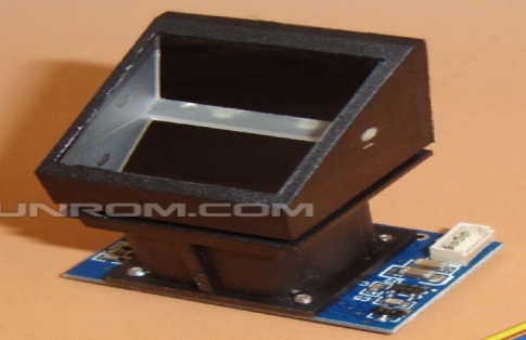
Fig 2.1 Fingerprint Module
Fingerprint module processing consists of two parts: fingerprint enrollment unit and fingerprint matching unit (the matching can be 1:1 or 1:N). During Enrolling period, the voter needs to enter and punch his/her finger towards the fingerprint module. The system will process the finger images, generating a template of the finger and produce results and stores the template. These templates are further used for matching. When matching, voter punches his/her fingerprint through the fingerprint module which further intakes through optical sensor and system will generate a template of the finger and compare it with templates of the finger library already stored in the database. For 1:1 matching, system will compare the current finger with the particular template designated in the Module; for 1: N matching, or searching, system will search the whole finger library for the matching finger. In both circumstances, system will return the matching result, success or failure. Based on the results, the kit is further connected with the alarm module.
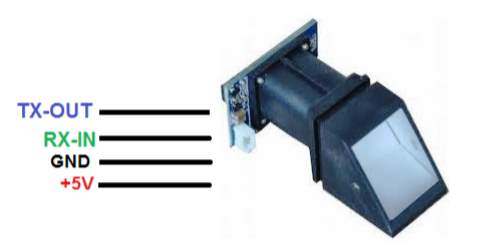
Fig 2.2 Fingerprint Module Connections
Hardware connection:-
Through serial interface communication, the Fingerprint Module may communicate with MCU of either 3.3V or 5V power: TD (pin 3 of P1) connects with RXD (receiving pin of MCU), RD (pin 4 of P1) connects with TXD (transferring pin of MCU). In RS-232 mode, level converting circuit should be added like MAX232 and placed between the module and pc.
Serial Connection protocol:-The mode is also known as semiduplex asynchronism serial communication, 56700bps is the baud rate to be set. User may have the choice of setting the baud rate between 9600~115200bps.Transferring frame format is about 10 bit: the low-level starting bit, 8-bit data with the LSB first, and an ending bit. There is no check bit.
Reset Time:-At power on, 500ms is the startup time for the module. During this period the module cannot take the input values for the upper computer
2.2.1 Features
- Integrated image collecting and algorithm chip together, All-in-one
- Fingerprint reader can be employed secondary development processes, like it can be embedded into a variety of end products.
- The practical advantages of this R305 module is low cost, Low power consumption, excellent performance, small size
- Precise module manufacturing techniques and Professional optical technology forms a key part in the manufacturing.
2.3 Introduction to LCD
LCD (Liquid Crystal Display) screen is an electronic display module and can be used in the wide range of applications. The LCD forms a vital part in any project as it is a way of communication between the user and the computer. A 16×2 LCD display is very basic module that consists of two lines each of sixteen bit and is very commonly used in various devices and circuits.
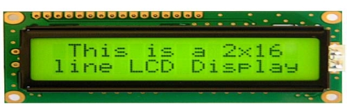
Fig 2.3 LCD Display
The LCD is a 16×2 that provides the display to the user in two lines. Each character in a LCD is displayed in a 5 x 7 matrix. Generally for a LCD unit, there are two registers namely the command and the data register. The command register is used to store the command instructions that were sent to it through the pc while the data register is used to store the data to be displayed on the screen. The LCD uses ASCII as the mode of reading and writing the values.
Advantages
- The required voltage is very small so that it can operate in any small voltage supplied units..
- Low power consumption. This is the important feature of the LCD module. It can operate for a long period of time by consuming very power.
Disadvantages of LCD
- LCD’s Devices are very slow. The ON and OFF times are quiet very large. Large.
- When used on DC, their life span is quite small. Therefore, they should be used with AC supplies having frequency less than 50 Hz.
2.3.1 Pin description
Table 2.2 Pin Configuration of LCD module
| Pin No | Pin Functions | Name given |
| 1 | Ground | Ground |
| 2 | Supply voltage to be given | Vcc |
| 3 | Variable resistor employed to adjust contrast | VEE |
| 4 | Register select: Command register when low. Data register when high | Register Select |
| 5 | Write and read options:- low to write to a register
High to read from a register. |
Read/write |
| 6 | Sends data to data pins | Enable |
| 7 | 8-bit data pins | DB0 |
| 8 | DB1 | |
| 9 | DB2 | |
| 10 | DB3 | |
| 11 | DB4 | |
| 12 | DB5 | |
| 13 | DB6 | |
| 14 | DB7 | |
| 15 | Backlight VCC (5V) | Led+ |
| 16 | Backlight Ground (0V) | Led- |
2.3.2 Features
- Operating voltage range is 3-20V ac.
- It has a slow decay time. Response time is 50 to 200 ms.
- Viewing angle is 100 degree.
- Invisible in darkness. Requires external illumination.
- Life time is limited to 50,000 hours due to chemical graduation.
CHAPTER-3
DEVELOPMENTS ACCOMPLISHED
3.1 Study of Block Diagram
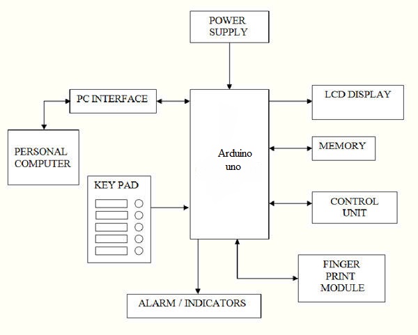
Fig 3.1 Overall Block Diagram
Figure 3.1 shows the overall block diagram of the proposed work. The work involves interfacing of various units and the modules involved are Arduino Uno, LCD Display, Memory, Control unit, Personal computer and alarm indicators.
A biometric system is designed using the main modules that are follows.
- Sensor module, which captures the Fingerprint data of an individual. The Fingerprint module records the fingerprints based on the concept of ridge and valley.
- Feature extraction module, in which the acquired Fingerprint data is processed and stored as a set of template set that will be used in future matching purposes. For example, the position and orientation of miniature points (local ridge and valley singularities) in a fingerprint image will be extracted for the purpose of processing to check its compatibity in matching module.
- Matcher module, in which the features extracted during recognition are compared against the stored templates to generate matching scores. The Matching scores were given by comparing the particular fingerprint with the fingerprints that were stored previously for the matching purposes. The matcher module also holds a decision making module, in which a user‘s identity is confirmed (verification) or a user‘s identity is established (identification) based on the matching score.
- System database module, which is used as a virtual database. A set of fingerprints were stored in a small memory chip that is used as a virtual database. Fingerprints obtained from a user or a voter is verified with the fingerprints that are stored in the memory chip using the matcher module.
- Hardware and software requirements
3.2.1 Hardware requirements
- ARDUINO Uno R3
- Fingerprint Sensor
- RS232
- LCD
- Buzzer
- Power Supply (+5V, +12V)
- PC
- Software requirements
- Arduino IDE
2) Proteus 8 Professional
3.3 Working description of Arduino Uno
3.3.1 Introduction
Arduino is an open source platform for prototyping based on user-friendly software. It provides a flexible base for engineers to experiment on designing interactive environments. They can be programmed for specific applications to create embedded systems which can control and sense real time parameters. It consists of a microcontroller ATmega328 which is programmed using the arduino software.
The Arduino R3/Genuino R3 is the Indian version of the Arduino Uno Board with an Arduino Uno Boot loader. It behaves like the arduino board and programmed using the arduino IDE.
Its main components are
- 14 digital input/output pins ( 6 can be used as PWM outputs)
- 6 analog inputs(can also be used for digital I/O – so a total of 20 digital I/O’s)
- 16 MHz crystal oscillator
- USB connection
- ICSP header
- reset button
3.3.2 List of on-board peripherals
Table 3.1 On-Board Peripherals of Arduino
| Function | Peripheral | Pin number |
| For digital outputs: | 1 LED | 13 |
| For digital inputs: | – | 2, 3, 4, 5, 6, 7, 8, 9, 10, 11, 12, 13 |
| pulse generation & wireless communication | – | 3, 5, 6, 9, 10, 11 |
| pulse decoding & wireless communication | – | 0,1 |
| analog sensors | – | A0. A1, A2, A3, A4, A5 |
3.3.3 The Microcontroller
The Arduino R3 comes with an ATMega 328 Microcontroller with an Arduino Uno Bootloader. The Bootloader facilitates the Programming of the IC from within the Arduino IDE.

Fig 3.2 Microcontroller AT328P-Pin Diagram
Memory
Memory can be broadly divided into 3 classes:
- 32KB Flash memory –This is the storage space of the compiled program of which the bootloader uses 0.5 KB.
- 2KB SRAM – This is mainly used during run time.
- 1KB EEPROM –This is used for storing data that should not be erased upon switching off power.
Power Setup
The Arduino R3 operates at 5 Volts. It can either be powered through USB cable from the computer or through the DC jack provided on the Board.
The DC Jack
The voltage regulator 7805 is provided in the board for obtaining 5v regulated output voltage. The input voltage applied can be between 7-25 volts DC power.
USB Power
When powered through the USB, the 500mA Re-settable fuse on the USB power line is used to abstain the board from drawing current in excess.
USB Connectivity
Since the ATmega328 does not use USB communication directly, the need for a dedicated IC arises. FTDI FT232 IC is used to communicate between the microcontroller and USB serially .The drivers required for the Serial to USB converter has to be installed.
Hardware
The Arduino R3 / Arduino Uno Boards have 20 programmable I/O’s. They are grouped mainly as
- Pins 0 to 13
- Pins 0 to 5 [Analog Inputs 0 to 5]
Digital I/O’s
The 20 I/O’s can accept digital signals as input as well as outputs. The digital pins are numbered from 0 to 19.The Digital Pins can be used for controlling LED’s, Relays and for accepting input from Push-Buttons, Digital Sensors
Analog I/O’s
Analog inputs can be given to pins A0-A5.An inbuilt ADC analog to digital converter is present that converts analog voltages in the range of 0 to 5 volts to a 10-bitvalue. Analog sensors that sense changes in temperature or light can work with these inputs.
Analog Output
The six pins marked PWM are pins dedicated to produce Analog Output Signal. They can produce analog voltages in the range of 0 to 5 volts with a resolution of 8- bits.They can be used for Intensity Control, Speed Control, Etc.
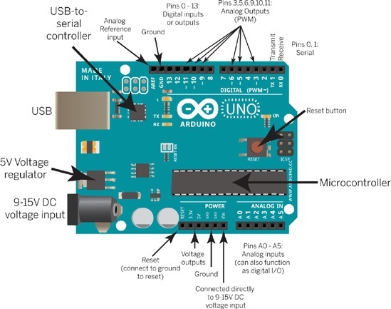
Fig 3.3 Arduino pin mapping
3.3.4 Pin diagram of Arduino Uno
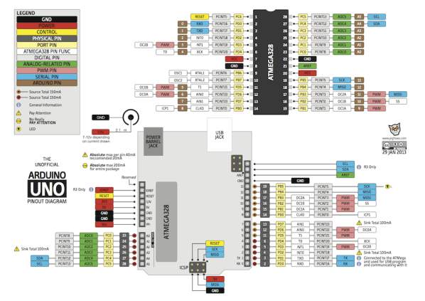
Fig 3.4 Pin configuration of Arduino uno
3.4 Working description of proposed algorithm
Working of the proposed algorithm mainly consists of two divisions:-
- Interfacing LCD with the Arduino unit
- Interfacing Fingerprint module with the Arduino unit.
3.4.1 Interfacing LCD with the arduino unit
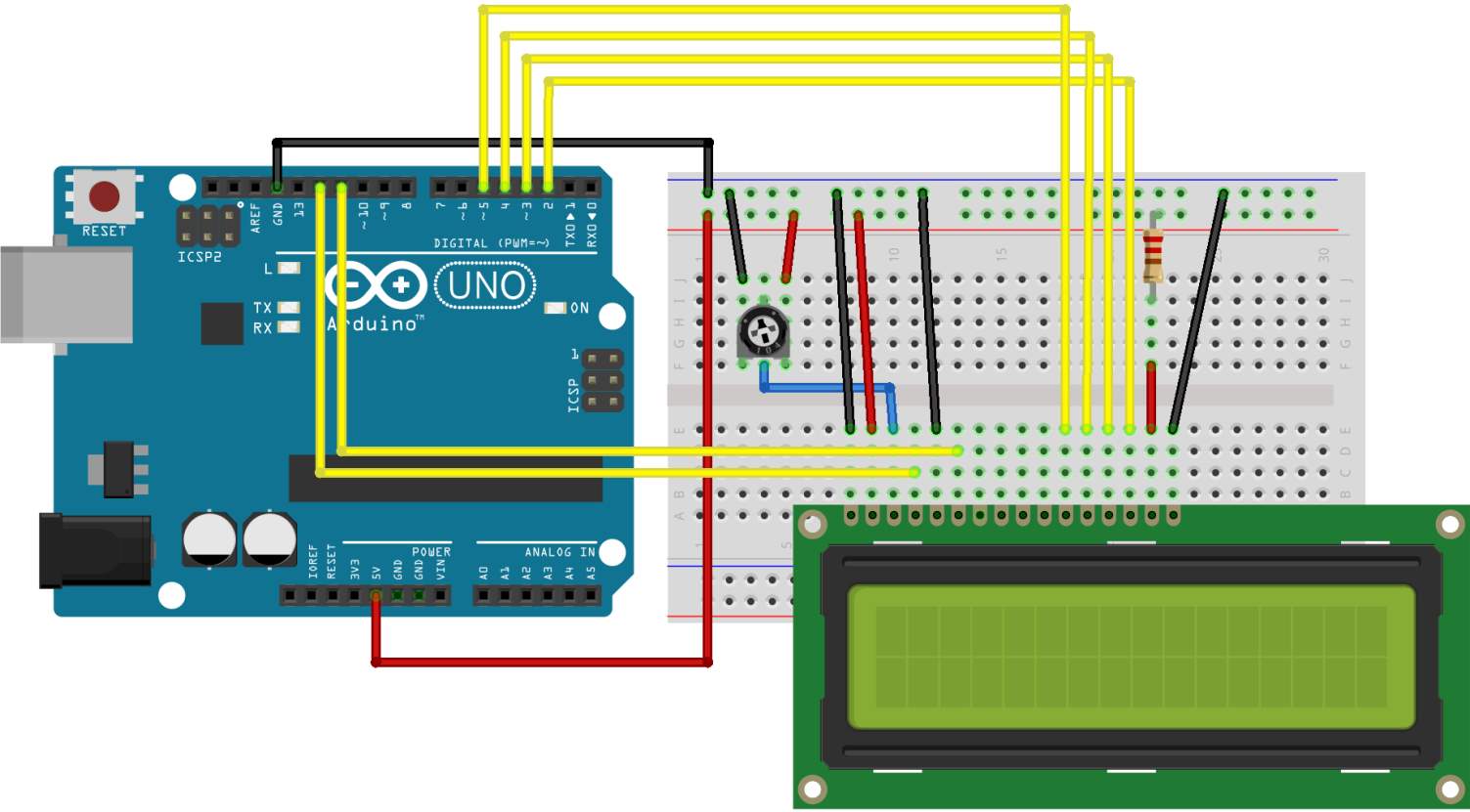
Fig 3.5 Interfacing LCD with Arduino
Wiring the LCD screen to the Arduino
To wire your LCD screen to your board, following pins should be connected as it:
- LCD RS pin to digital pin 12
- LCD Enable pin to digital pin 11
- LCD D4 pin to digital pin 5
- LCD D5 pin to digital pin 4
- LCD D6 pin to digital pin 3
- LCD D7 pin to digital pin 2
3.4.2 Interfacing Arduino with fingerprint module
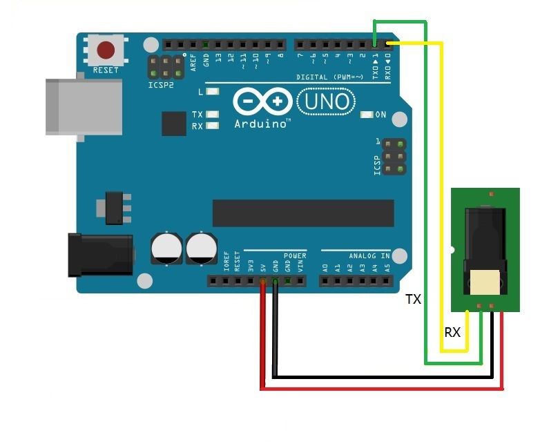
Fig 3.6 Interfacing Fingerprint Module with the Arduino
The connection between the Fingerprint module and the Arduino should be as:
- TX of module (Green wire) should be connected to RX of Arduino (Pin 2).
- RX of module (Yellow or White wire) should be connected to TX of Arduino (Pin 3).
- VC of module (RED wire) should be connected to 5V pin of Arduino.
- GND of module (Black wire) should be connected to GND of Arduino.
3.5 Flow chart and its description
3.5.1 Flow Chart:-
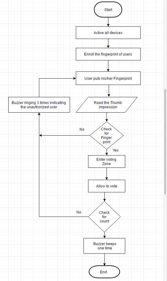
Fig 3.7 Flow Chart
The above flow chart describes the working of the proposed system. The User enters the polling booth verifying his/her identity and voting. The entire system of functionalities was depicted above in the flow diagram.
3.5.1 Flow chart description
Step1: ON Power supply
Step2: Active all devices
Step3: Enroll the fingerprint of users which is given in AADHAR CARD
Step4: user puts his/her fingerprint
Step5: if finger print not matched go to step 4.
Step6: if matched then allowed to voting
Step7: Enter voting zone
Step8: voting completed then buzzer beeps single time
Step9: go to Step4
Step10: buzzer beep three time which indication of unauthorized user
CHAPTER-4
RESULTS AND CONCLUSION
4.1 Result
The Microcontroller based Fingerprint recognition method works in a way that the entry of unauthorized user will be indicated by the alarm unit.
The scenario based on the possible practical assumptions is as follows
Scenario 1: Authorized user entry within same locality Voter
The Voter who is eligible to cast his/her vote will enter into the polling booth. The initial process of the verification involves the fingerprint verification. The user will be guided into the verification part of the polling booth. The user will punch his/her finger in the fingerprint module. The fingerprint values were taken by the sensor unit will compare it to the feature set. In case of the authorized user, fingerprint unit will grant its permission for the user to caste his/her vote.
Scenario 2: Unauthorized user entry with different locality Voter
The voter in this case is actually authorized but, the voter enters the wrong polling booth. The particular locality will be assigned with only one polling booth. The user may accidentally enter into a wrong polling booth. In such a case, the voter will be directed to his/her assigned polling booth.
Scenario 3: User trying to repeat his/her votes
The User trying to indulge in malpractice activity by providing a re-entry to the polling booth .In this case, the user will get caught in the verification section. On further investigation with the incident, the user’s activity will be considered as punishable offence if necessary.
Scenario 4: The different person entering the booth with the purpose of bogus voting
If a person enters the polling booth with the only intention of casting fake votes will get caught in the verification section. On further investigation with the incident, the user’s activity will be considered as punishable offence if necessary.
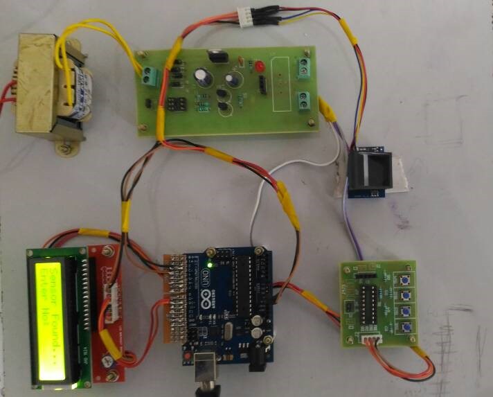
Fig 4.1 Kit showing the proposed work
4.2 Conclusion
The Basic idea of the project is to overcome the current difficulties faced by the government and the people during election times. And also to eliminate the fake voting, this method will have its upper hand. Thus, the proposed system will verify the fingerprints of the voter with the database of the government and produce the results in a more genuine way. Due to the lack of Internet access in the remote places and small villages, this method is still not in practice. Being a developing nation, over a course of time India can provide internet to remote places. This proposed work will come to practice in few years.
4.3 Future scope
This method can be implemented in the near future because of its high dependency in Internet connectivity. Being a developing nation, India is emerging to a point where it can provide internet to remote places and small villages. It may take few years for this project to get implemented practically.
APPENDIX-A
Code to show a blank display
// Red connects to +5V
// Black connects to Ground
// White goes to Digital 0
// Green goes to Digital 1
void setup() {}
void loop() {}
APPENDIX-B
Code to delete an enrolled user
#include <Adafruit_Fingerprint.h>
#include <SoftwareSerial.h>
uint8_t getFingerprintEnroll(uint8_t id);
void setup()
{
Serial.begin(9600);
Serial.println(“Delete Finger”);
// set the data rate for the sensor serial port
finger.begin(57600);
if (finger.verifyPassword()) {
Serial.println(“Found fingerprint sensor!”);
} else {
Serial.println(“Did not find fingerprint sensor :(“);
while (1);
}
}
void loop()
{
while (!Serial);
delay(500);
Serial.println(“Type in the ID # you want delete…”);
uint8_t id = 0;
while (true) {
while (! Serial.available());
char c = Serial.read();
if (! isdigit(c)) break;
id *= 10;
id += c – ‘0’;
}
Serial.print(“deleting ID #”);
Serial.println(id);
deleteFingerprint(id);
}
uint8_t deleteFingerprint(uint8_t id) {
uint8_t p = -1;
p = finger.deleteModel(id);
if (p == FINGERPRINT_OK) {
Serial.println(“Deleted!”);
} else if (p == FINGERPRINT_PACKETRECIEVEERR) {
Serial.println(“Communication error”);
return p;
} else if (p == FINGERPRINT_BADLOCATION) {
Serial.println(“Could not delete in that location”);
return p;
} else if (p == FINGERPRINT_FLASHERR) {
Serial.println(“Error writing to flash”);
return p;
} else {
Serial.print(“Unknown error: 0x”); Serial.println(p, HEX);
return p;
}
}
APPENDIX-C
Code to check the fingerprint sensor
#include <Adafruit_Fingerprint.h>
#include <SoftwareSerial.h>
#include<LiquidCrystal.h>
LiquidCrystal lcd(8,9,4,5,6,7);
int getFingerprintIDez();
SoftwareSerial mySerial(2, 3);
void setup()
{
lcd.begin(16, 2); //LCD Initialize
lcd.clear();
lcd.print(” ELECTRONIC “);
lcd.setCursor(0,1);
lcd.print(“VOTING MACHINE”);
delay(1000);
lcd.clear();
while (!Serial);
Serial.begin(9600);
Serial.println(“Finger detect test”);
lcd.clear();
lcd.print(“Check the sensor…”);
lcd.setCursor(0,1);
// set the data rate for the sensor serial port
finger.begin(57600);
if (finger.verifyPassword()) {
Serial.println(“Found fingerprint sensor!”);
lcd.clear();
lcd.print(“Check the sensor…”);
lcd.setCursor(0,1);
} else {
Serial.println(“Did not find fingerprint sensor :(“);
while (1);
}
Serial.println(“Waiting for valid finger…”);
lcd.print(“No Sensor Found…”);
lcd.setCursor(0,1);
}
void loop() // run over and over again
{
getFingerprintIDez();
delay(50); //don’t ned to run this at full speed.
}
uint8_t getFingerprintID() {
uint8_t p = finger.getImage();
switch (p) {
case FINGERPRINT_OK:
Serial.println(“Image taken”);
break;
case FINGERPRINT_NOFINGER:
Serial.println(“No finger detected”);
return p;
case FINGERPRINT_PACKETRECIEVEERR:
Serial.println(“Communication error”);
return p;
case FINGERPRINT_IMAGEFAIL:
Serial.println(“Imaging error”);
return p;
default:
Serial.println(“Unknown error”);
return p;
}
// OK success!
p = finger.image2Tz();
switch (p) {
case FINGERPRINT_OK:
Serial.println(“Image converted”);
break;
case FINGERPRINT_IMAGEMESS:
Serial.println(“Image too messy”);
return p;
case FINGERPRINT_PACKETRECIEVEERR:
Serial.println(“Communication error”);
return p;
case FINGERPRINT_FEATUREFAIL:
Serial.println(“Could not find fingerprint features”);
return p;
case FINGERPRINT_INVALIDIMAGE:
Serial.println(“Could not find fingerprint features”);
return p;
default:
Serial.println(“Unknown error”);
return p;
}
// OK converted!
p = finger.fingerFastSearch();
if (p == FINGERPRINT_OK) {
Serial.println(“Found a print match!”);
} else if (p == FINGERPRINT_PACKETRECIEVEERR) {
Serial.println(“Communication error”);
return p;
} else if (p == FINGERPRINT_NOTFOUND) {
Serial.println(“Did not find a match”);
return p;
} else {
Serial.println(“Unknown error”);
return p;
}
// found a match!
Serial.print(“Found ID #”); Serial.print(finger.fingerID);
Serial.print(” with confidence of “); Serial.println(finger.confidence);
}
// returns -1 if failed, otherwise returns ID #
int getFingerprintIDez() {
uint8_t p = finger.getImage();
if (p != FINGERPRINT_OK) return -1;
p = finger.image2Tz();
if (p != FINGERPRINT_OK) return -1;
p = finger.fingerFastSearch();
if (p != FINGERPRINT_OK) return -1;
// found a match!
Serial.print(“Found ID #”); Serial.print(finger.fingerID);
Serial.print(” with confidence of “); Serial.println(finger.confidence);
return finger.fingerID;
}
APPENDIX-D
4. Code to enroll a user
#include <Adafruit_Fingerprint.h>
#include <SoftwareSerial.h>
#include<LiquidCrystal.h>
void setup()
{
lcd.begin(16, 2); //LCD Initialize
lcd.clear();
lcd.print(” ELECTRONIC “);
lcd.setCursor(0,1);
lcd.print(“VOTING MACHINE”);
delay(1000);
lcd.clear();
while (!Serial);
delay(500);
lcd.clear();
lcd.print(“Check the sensor…”);
lcd.setCursor(0,1);
Serial.begin(9600);
Serial.println(“Fingerprint sensor enrollment”);
// set the data rate for the sensor serial port
finger.begin(9600);
if (finger.verifyPassword()) {
Serial.println(“Found fingerprint sensor!”);
lcd.print(“Sensor Found…”);
lcd.setCursor(0,1);
} else {
Serial.println(“Did not find fingerprint sensor :(“);
lcd.print(“No Sensor Found…”);
lcd.setCursor(0,1);
while (1);
}
}
uint8_t readnumber(void) {
uint8_t num = 0;
boolean validnum = false;
while (1) {
while (! Serial.available());
char c = Serial.read();
if (isdigit(c)) {
num *= 10;
num += c – ‘0’;
validnum = true;
//} else if (validnum) {
return num;
}
}
}
void loop() // run over and over again
{
Serial.println(“Ready to enroll a fingerprint! Please Type in the ID # you want to save this finger as…”);
id = readnumber();
Serial.print(“Enrolling ID #”);
Serial.println(id);
while (! getFingerprintEnroll() );
}
uint8_t getFingerprintEnroll() {
int p = -1;
Serial.print(“Waiting for valid finger to enroll as #”); Serial.println(id);
while (p != FINGERPRINT_OK) {
p = finger.getImage();
switch (p) {
case FINGERPRINT_OK:
Serial.println(“Image taken”);
break;
case FINGERPRINT_NOFINGER:
Serial.println(“.”);
break;
case FINGERPRINT_PACKETRECIEVEERR:
Serial.println(“Communication error”);
break;
case FINGERPRINT_IMAGEFAIL:
Serial.println(“Imaging error”);
break;
default:
Serial.println(“Unknown error”);
break;
}}
// OK success!
p = finger.image2Tz(1);
switch (p) {
case FINGERPRINT_OK:
Serial.println(“Image converted”);
break;
case FINGERPRINT_IMAGEMESS:
Serial.println(“Image too messy”);
return p;
case FINGERPRINT_PACKETRECIEVEERR:
Serial.println(“Communication error”);
return p;
case FINGERPRINT_FEATUREFAIL:
Serial.println(“Could not find fingerprint features”);
return p;
case FINGERPRINT_INVALIDIMAGE:
Serial.println(“Could not find fingerprint features”);
return p;
default:
Serial.println(“Unknown error”);
return p;
}
Serial.println(“Remove finger”);
delay(2000);
p = 0;
while (p != FINGERPRINT_NOFINGER) {
p = finger.getImage();
}
Serial.print(“ID “); Serial.println(id);
p = -1;
Serial.println(“Place same finger again”);
while (p != FINGERPRINT_OK) {
p = finger.getImage();
switch (p) {
case FINGERPRINT_OK:
Serial.println(“Image taken”);
break;
case FINGERPRINT_NOFINGER:
Serial.print(“.”);
break;
case FINGERPRINT_PACKETRECIEVEERR:
Serial.println(“Communication error”);
break;
case FINGERPRINT_IMAGEFAIL:
Serial.println(“Imaging error”);
break;
default:
Serial.println(“Unknown error”);
break; }
}
// OK success!
p = finger.image2Tz(2);
switch (p) {
case FINGERPRINT_OK:
Serial.println(“Image converted”);
break;
case FINGERPRINT_IMAGEMESS:
Serial.println(“Image too messy”);
return p;
case FINGERPRINT_PACKETRECIEVEERR:
Serial.println(“Communication error”);
return p;
case FINGERPRINT_FEATUREFAIL:
Serial.println(“Could not find fingerprint features”);
return p;
case FINGERPRINT_INVALIDIMAGE:
Serial.println(“Could not find fingerprint features”);
return p;
default:
Serial.println(“Unknown error”);
return p;
}
// OK converted!
Serial.print(“Creating model for #”); Serial.println(id);
p = finger.createModel();
if (p == FINGERPRINT_OK) {
Serial.println(“Prints matched!”);
} else if (p == FINGERPRINT_PACKETRECIEVEERR) {
Serial.println(“Communication error”);
return p;
} else if (p == FINGERPRINT_ENROLLMISMATCH) {
Serial.println(“Fingerprints did not match”);
return p;
} else {
Serial.println(“Unknown error”);
return p;
}
Serial.print(“ID “); Serial.println(id);
p = finger.storeModel(id);
if (p == FINGERPRINT_OK) {
Serial.println(“Stored!”);
} else if (p == FINGERPRINT_PACKETRECIEVEERR) {
Serial.println(“Communication error”);
return p;
} else if (p == FINGERPRINT_BADLOCATION) {
Serial.println(“Could not store in that location”);
return p;
} else if (p == FINGERPRINT_FLASHERR) {
Serial.println(“Error writing to flash”);
return p;
} else {
Serial.println(“Unknown error”);
return p;
} }
References
[1]. Firas I. Hazzaa ,Seifedine Kadry , Oussama Kassem Zein, ‘Web-Based Voting System Using Fingerprint: Design and Implementation’, International Journal of Computer Applications in Engineering Sciences, Volume 2, Issue 4, December 2012
[2]. Mayuri U. Chavan, Priyanka V. Chavan, Supriya S. Bankar, ‘Online Voting System Powered by Biometric Security using Cryptography and Stegnography’, International Journal of Advance Research in Computer Science and Management Studies, Volume 1, Issue 7, December 2013
[3] Anil K. Jain and David maltoni. , Handbook of Fingerprint Recognition, Springer-verlag New York, Inc., Secaucus, NJ, USA, 2003
Cite This Work
To export a reference to this article please select a referencing stye below:
Related Services
View all


Related Content
All TagsContent relating to: "Technology"
Technology can be described as the use of scientific and advanced knowledge to meet the requirements of humans. Technology is continuously developing, and is used in almost all aspects of life.
Related Articles

DMCA / Removal Request
If you are the original writer of this dissertation and no longer wish to have your work published on the UKDiss.com website then please: