Next Generation Telecommunication Network
Info: 10056 words (40 pages) Dissertation
Published: 9th Dec 2019
Tagged: CommunicationsEngineering
Table of Contents
1.3 Geographic and Demographic
1.3.1 Past & Current Population
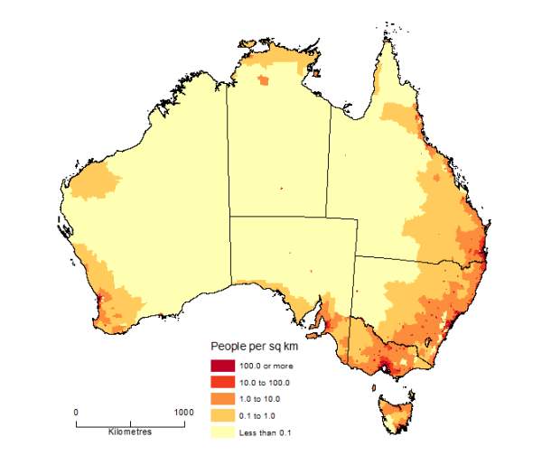
1.3.4 Australia Population Density
1.4 Past & Current Infrastructure
3.2 Core Network Topology Design
3.2.2 Advantages & Disadvantages of Core Network Design
3.3.1 Advantages & Disadvantages of Aggregation Network Design
3.4 Aggregation Network Topology Diagram
4.1.1 High Density Residential Areas
4.1.2 Advantages & Disadvantages of HDRA Technology
4.1.3 High Density Residential Areas Network Diagram
4.1.4 High Density Business Areas
4.1.2 Advantages & Disadvantages of HDBA Technology
4.1.5 High Density Business Areas Network Diagram
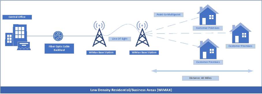
4.2.1 Low Density Residential/Business Areas
4.2.2 Advantages & Disadvantages of WiMAX Technology
4.2.3 Low Density Residential/Business Areas Network Diagram
4.3.2 Advantages & Disadvantages of Satellite: VSAT Technology
4.3.3 Remote Populated Areas Network Diagram
6.0 Service and Network Management
6.1 Simple Network Management Protocol
From Internet of Things to internet of every thing
Australians accessing online video and audio content, by age, June 2017 (percentage)
Social media use, by age, June 2017 (percentage)
Use of communications apps, by activity, June 2017(percentage)
Use of communications apps, by activity and age, June 2017 (percentage)
1.0 Executive Summary
1.1 Objectives
This project will assist in developing a high-level, end-to-end design of a national next generation telecommunications networks, which will serve all major cities and regional areas of Australia. The reasons why we are upgrading our infrastructure is to keep up with the demands as network usage is constantly increasing, but also to provide a more stable network as reliability is vital but most important for a more secure network, as we want to perform our tasks knowing our data is secure.
1.2 Background
Telecommunications and ICTs have been acknowledged as a driver of economic and social development, reducing poverty and creating wealth. This development creates a chance to encourage exchange and monetary advancement by and large, and also business improvement and employment creation, particularly for entrusted populations such as indigenous people groups and people with incapacities.
Infrastructure is essential to accomplishing the objective of digital incorporation, sustainable and cost-effective in order to provide access to ICTs and services for everyone. The ICT sector is described by fast technology change and by combination of innovative stages for telecommunications, information transportation, distribution and computing. The arrangement of regular system foundations for various telecommunication services and applications and the advancement to all IP-based remote and wired cutting edge systems – grants new opportunities, however these opportunities are surrounded by difficult challenges.
Building up telecommunication infrastructure, Australia has invested heavily in PSTN technology and PLMN networks which are presently facing huge challenges in terms of migration from their existing technology to cutting edge systems networks such as NBN. To overcome these challenges, taking in consideration multiple factors such as the cost related, resources and most important the knowledge to plan for a smooth migration to NGN and QoS for those high date consumptions media services.
Migrating from Australia current infrastructure to an NGN platform requires in taking multiple factors in consideration and planning every aspect carefully such as the core and access network levels. The access network is one of the key parts in giving broadband services, which has the capability of turning into a genuine bottleneck for the conveyance of interactive media applications. It is perceived that the access network is a standout amongst the costliest segments of telecommunication infrastructure contrasted with different parts of the network.
The access network, thus, must to be agreed when examining the status of a telecommunication network foundation for development toward NGN. Without real access network orchestrating, it would challenge for an NGN implementation strategy to succeed. In this way, the access network is one of the essential focus domains in migration to NGN.
The requirement for development of NGN in rural regions is self-evident, as a huge extent of the populace, live in rural regions which have requirements that involved the access of ICT.
Considering these areas when implementing the NGN is hugely important as most of the populace living in rural regions, having low education levels, require sight and sound services to encourage simple access to relevant information and services.
NGN is viewed as a social infrastructure on which broadband services can be given, opening new open doors in the telecommunication business. Nations can profit by NGN arrangement with an extensive variety of cutting-edge ICT-based services and applications in building the information society; implementing systems for the public security and catastrophe alleviation amid crisis communication, particularly early cautioning frameworks for spread of crisis information; and, enhancing access to information and learning in the rural regions and engaging underestimated networks for digital consideration.
• Unrestricted access to service providers: Regardless of which service provide you choose, they will all go through NGN infrastructure cutting down installation cost when switching providers.
1.3 Geographic and Demographic
A major point to take into considering is the geographic and demographic of Australia to calculate our target audience but also to take into consideration future expansion. Without this information can leave to significant errors even the failure of the entire project. As of now the estimated current population of Australia is around 24,843,333. The population density in around 3 per km2 (8 people per mi2). The total land area is 7,682,300 Km2 (2,966,151 sq. miles). 90.0 % of the population is urban (22,301,673 people in 2018). The median age in Australia is 37.5 years.
1.3.1 Past & Current Population
| Year | Population | Yearly Change | Migrant (net) | Median Age | Fertility Rate | Density (P/Km²) | Urban Population | ||
| % | Total | % | Total | ||||||
| 2018 | 24,772,247 | 1.32 | 321,686 | 169,993 | 37.5 | 1.87 | 3 | 88.8 | 22,301,673 |
| 2017 | 24,450,561 | 1.35 | 324,713 | 169,993 | 37.5 | 1.87 | 3 | 90.0 | 21,996,082 |
| 2016 | 24,125,848 | 1.37 | 326,292 | 169,993 | 37.5 | 1.87 | 3 | 89.9 | 21,692,663 |
| 2015 | 23,799,556 | 1.47 | 335,898 | 182,621 | 37.4 | 1.89 | 3 | 89.9 | 21,392,649 |
1.3.2 Population Forecast
| Year | Population | Yearly Change | Migrant (net) | Median Age | Fertility Rate | Density (P/Km²) | Urban Population | ||
| % | Total | % | Total | ||||||
| 2020 | 25,398,177 | 1.31 | 319,724 | 169,993 | 37.9 | 1.83 | 3 | 90.2 | 22,910,275 |
| 2025 | 26,857,068 | 1.12 | 291,778 | 150,000 | 38.9 | 1.80 | 3 | 90.9 | 24,400,230 |
| 2030 | 28,234,742 | 1.01 | 275,535 | 150,000 | 39.8 | 1.78 | 4 | 91.5 | 25,834,777 |
| 2035 | 29,526,448 | 0.90 | 258,341 | 150,000 | 40.6 | 1.77 | 4 | 92.2 | 27,222,968 |
1.3.3 Population by State
| State | Population (m) |
| New South Wales | 7.3 |
| Victoria | 6.0 |
| Queensland | 4.4 |
| South Australia | 1.3 |
| Western Australia | 2.2 |
| Tasmania | 0.5 |
| Northern Territory | 0.2 |
| Australian Capital Territory | 0.4 |
| Australia | 22.3 |
1.3.4 Australia Population Density


2.0 Design Overview
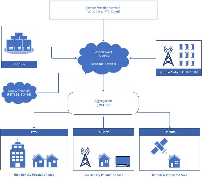
The next generation network will grant broadband connectivity across the entire country regardless of the technology or locations. As the center technology or should we say the Aggregator will be IP over DWDM, which is utilized to connect the various access technology that the service provides have to offer/available. Using Multiprotocol Label Switching (MPLS), will guarantee the separated Quality of Service (QOS) for each network/s. The network is separated into three main layers which are; Core, Aggregation, and Access networks.
The responsibilities for each layer are as follow:
- Core Layer: Responsible for utilizing MPLS packets as the routing layer for the aggregation/backbone network. This network is linked to existing legacy technologies such as PSTN, 2G, 3G and 4G networks.
- Aggregation Layer: Responsible for utilizing the technology DWDM (Dense Wavelength Division Multiplexing). This layer is also responsible to connect with the Access layer which is associated with end-user.
- Access Layer: This layer compared to other layers can be completely different, as it offers multiple technology to connect the user to the network. Depending which technology, we use it depends of multiples factors such as the location, population and other needs. As we are 3 main types of connections:
- Fiber to the Premises: Used on high population areas such as the CBD area.
- WiMax: Used for low population areas, but areas that are not classified as remote areas.
- Satellite: Used for remote areas, as the cost of running fiber infrastructure is too costly and does not have a returned valued of investment.
All of these proposed access technologies has a service layer allowing connectivity and simplicity to manage. The network design diagram is separated based upon the layered architecture.
 2.1 Network Diagram Design
2.2 Layered Structure
Core Network Layer: This is the central/backbone of the network. Its core functionality is to provide communication across different access technology but also to provide communication across external existing networks.
- MPLS: Known as Multi-Protocol Label Switching is the method used for choosing and fixing the trail for the packets. Operating Layer 2.5 of the OSI Model. The way label switching works on MPLS is the first devices does a routing lookup searching for the final destination router, it then pre-determined the path from the current location to the final router. “The router applied a label/shim based on this information. Future routers use the label to route the traffic without the need of perming any additional IP lookups. Once the pack has reached the final destination router the label is removed, and the packet is delivered via normal IP routing.” [4]
- IP: Packet switched network which is functioned by cutting large amount of data into smaller packets. Each packet contains a header, payload and trailer. The packet header has vital information for the packet to travel such as the source and destination address, protocol, packet number. The payload contains the data of the packet, this can be anything the user is sending. The trailer also known as the footer, contains the data to show end of packet and error correction (CRC). Packets then choose the best route which contains the least number of hops.
Access Network Layer: The access layer is responsible for connecting users to their immediate service providers. First the communications start by enabling users to communicate with the communication system to allow the start information exchange/transmission. These communications can either be wired and wireless or broadband and narrowband. The below technologies have been chosen to implement within our design:
- FTTP: Known asFiber to the Premises, is when the fiber cable end point is to the Premises. For example, the from the point of Interconnect to the premises.
- WiMax: Stands for Worldwide Interoperability for Microwave Access. It is a wireless broadband technology similar to WiFi but at a much higher speed over great distances and for greater number of users. It works by pointing out a line-of-sign to other WiMax transmitters to provide connectivity around the designated area. It is based on IEEE 802.16 wireless broadband standard.
- Satellite: “according to article 1.113 of the International Telecommunication Union´s (ITU) ITU Radio Regulations (RR) defined as “A radio link between a transmitting earth station and a receiving earth station through one satellite. A satellite link comprises one up-link and one down-link”
Aggregation Network: Is the responsible technology to connect multiple network access networks and provide connectivity by being connected to the Core Network. In terms of telecommunication network, the aggregation network is commonly placed between the core layer and access layer, so it can extend the reachability of the core network to the access layer network. The technologies used in the Aggregation varies on multiple factors such as the core and access layer, coverage area and geographical state.
- DWDM: Known as Dense Wavelength Division Multiplexing is a technology used to combine numerous multiplexes of optical carrier signals onto a single fiber using different wavelength. This grant complete separation of the data streams.
2.3 Objective of Design
Today telecommunication technology is speared into four major technology of communication – Voice Telephone, Internet, Cable TV, Mobile Networks. These communications systems will soon not have the capacity to keep up with the demand and will need a develop a new form of technology that will keep up with the current and future demands. The demands are increasing significant because of the new data-consuming services around us such as: cloud computing, high volume of data, high definition videos, quality voice calls, video broadcasting and many more high-quality-data-consuming services.
With the demand of rich services such as video, data and voice many organizations required a network infrastructure that can carry out all these services without difficulties, this is when NGN comes in and evolves the world.
Security is an important factor take into consideration. As the rise of cybersecurity increases and the demand for cybersecurity roles increase world-wide, making everyone’s data secured is extremely vital. NGN will provide advanced intrusion detecting systems, defense for denial-of-services, will monitor and log all traffic, whilst implementing firewall to add an extra layer of security. As we also come to the new era of technology known as Artificial Intelligence this will decrease significant cyber-crime or even stop it as machines will be able to think by themselves without human interaction.
Apart from security, many more benefits are associated with the implementation of NGN such as:
- Transmission cost is lower: This is due to the physical layer, which is the optic fiber cable that can transmit data without consuming a large amount of power.
- Greater power saving: The NGN is more efficient and power saving due to its technology which will bring the cost of operating significant down.
- Less space: As technology evolves so does the speed and the size, the NGN network will use less room than the Voice, Internet and Cable TV infrastructures. Less room usually mean less consumption.
- Less O&M cost: As we are migrating 3 networks into 1, the cost of operating and maintaining will be much less.
- Wider range services at faster speeds: This is what the technology does, offers more people connectivity but also provides it at a high quality.
- Packet-based transfers: Uniting all different networks into one, operating on the layer 2 & 3.
- Software-defined networking: Since the network will be software based, this means it’s easier to manage as you only require a computer.
- Redundant design: To achieve 100% service availability guaranteed, redundancy should be a key factor to avoid any point of failure.
- Total Flexibility: With technology constantly changing, the demand of applications may increase extraordinary hence the network should be flexible.
- Scalability: Ensuring the network is design in such way that it can handle the growing demand for the future.
3.0 Core Network Design
3.1 Core Network Technology
Our next generation network in made up of IP/MPLS technology. Multi-Protocol Label Switching is a technique that involves in creating a path for routing packets. It operates in the Layer 2.5 and works with Layer 2 & 3 of the OSI Model. The way label switching works on MPLS is the first devices does a routing lookup searching for the final destination router, it then pre-determined the path from the current location to the final router. IP/MPLS routing layers can be utilized to achieve two main functions; Provider Edge routing & Provider routing, which chains all the IP services that are linked from the client and the MPLS is utilized to route the packets/segments towards their final destination address.
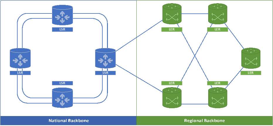
In our proposed design, the core router is connected to 3 other core routers in the national backbone under the ring topology. In terms of the regional backbone it is connected in a mesh topology. Optic fiber cables are used to connect the core router in order to achieve the highest speeds, but also to achieve QoS. Most important redundancy is taken into consideration as if one of these routers fails, we have alternativity core routers adapting immediately in case any router fails.
When talking about national backbone, we must also take into consideration multiple factors, to guaranteed QoS but also 100% availability. The national backbone is corrected in a ring topology with not 1 but 2 double connections using the super-fast high-speed fiber cable between each router to guarantee/support availability at all times and resiliency. In the situation that any link fails, the topology is design in such way that it would use the second connections to continue running the service simultaneously.
In terms of the regional backbone network, our design uses a meshed topology based on multiple reasons. The meshed topology was chosen due to the fact that we want to ensure that all the routers have multiple points of connections, and would be using the chosen topology due to the difficulty in implementing but also the cost associated with it.
3.2 Core Network Topology Design
3.2.1 Routers Roles
- LSR: The Label Switching Router is responsible to route packets to ensure that all of the packets carried in a specifies route and will remain the allocated path over a backbone.
- LER: The Label Edge Router used in the edges of a MPLS network. Its responsibilities for encapsulating packets inside the MPLS label switching path.
3.2.2 Advantages & Disadvantages of Core Network Design
The advantages & disadvantages of MPLS are as follow:
Advantages:
- Quality of Service (QoS) – With the use of MPLS technology it is design for QoS. This technology is among the best in order to have reliable and quality speeds.
- Faster Speeds – Due to Labeling technology, the performance is faster compared to the standard technologies.
- Multi-Layer Support – As MPLS layers operations, it supports Layer 2 & 3.
- Rapid Restoration – MPLS restoration is significant much faster than the rest, increasing efficiency and productivity.
- Redundancy – With the implementation of dual link connectors, a redundant link is used in the case of any link going offline or breaking.
- Usability – MPLS allows you to add new remote connections without having to purchase additional hardware system and using the existing technology located at the primary site. By have cloud-based technology it does not require the point to point connectivity.
Disadvantages:
- Expensive – Considering it’s classified as an advanced way of technology, it can cost more than Ethernet, however the cost is less then T1 lines.
- Lack of Total Control – Service provides are responsible for having to configure the overall networks. Working along with service providing routing MPLS traffic while using dynamic routing.
3.3 Aggregation Network Layer
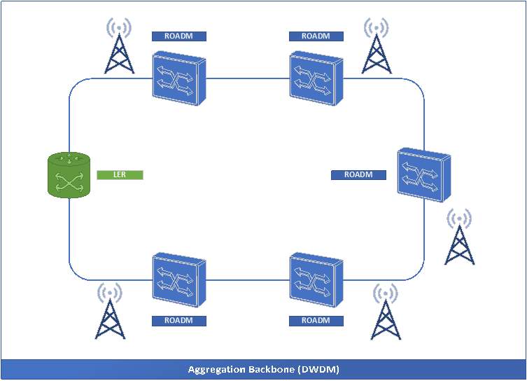
This is the network layer that is responsible for providing communication from the Access Layer to the Core Layer by extending it Core Layer functions through the Access layer. This allows the aggregation layers to operate between Layer 1 & 2. The core functionalities of this layers is the availability, fast switching, scaling is extended to this layer as demonstrated in the diagram below.
The LER router which acts as the Edge router is connected to numerous aggregation routers. In our aggregation diagram we are using ROADMs which stands for Reconfigurable ADD-Drop Multiplexer, which are the programmed form of Optical ADD-Drop Multiplexer. Using ROADMs allows our network to avoid the conversion of optical to electrical signal and vice versa meaning faster network. ROADM’s have many benefits and are not limited to providing broadband service to the end user in the situation that the Access Technology fails, which is extremely unlikely due to the strategic of redundancy we have in place. A single Dense Wavelength Division Multiplexing (DWDM) ring can be utilized to connect numerous Access technology. Depending on population, geographical location and numbers of user we can determine how many ROADM’s we need to implement.
3.3.1 Advantages & Disadvantages of Aggregation Network Design
Below is a list of advantages within the aggregation network layer:
Advantages:
- Increased Bandwidth – Due to the optic fiber capacity, the bandwidth is increase over the single fiber link.
- Optimization – The ability to send different data streams on the same connection.
- Future Growth – The ring topology enables us for scaling the network for the future.
Disadvantages:
- Cost-Effective – It is not cost effective for low channels, as best practice is recommended to use CWDM.
- Complex Technology – The technology uses complicated transmitter and receiver’s technology, but also the difficulty in implementing this technology in terms of network design and management.
3.5 Geographical Analysis
In terms on how Australia is connected to the Internet is by the rest of the world high-speed submarine optical cable. These cables land at Alexandria and Paddington (NSW) and Perth (WA). As a result, we are required to install 7 core backbone networks at the following locations.
- 2 New South Wales
- 1 Victoria
- 1 Western Australia
- 1 South Australia
- 2 Queensland
As New South Wales carries the largest population in Australia and also carries the submarine optical cable, it would be best practice to have an additional backbone to act as a gateway for the international traffic.
In terms of the regional infrastructure it will remain the same, however in terms of the LER technology it depends upon numerous factors such as the number of users and bandwidth in demand by the users.
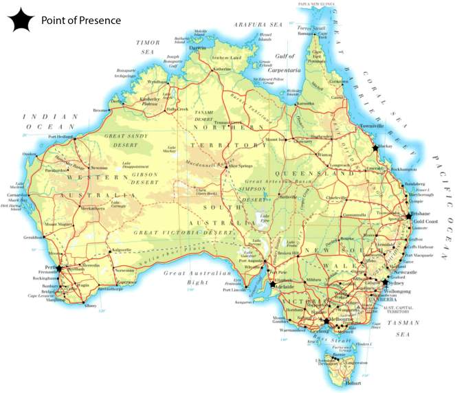 Geographical Map
4.0 Access Network Design
The Access network is responsible for connecting users to the immediate service provider. The Access network is separated into three main categories:
- Wired
- Wireless
- Mobile Access
In our design we use all three to provide access solution across the entire country.
4.1 Wired Access
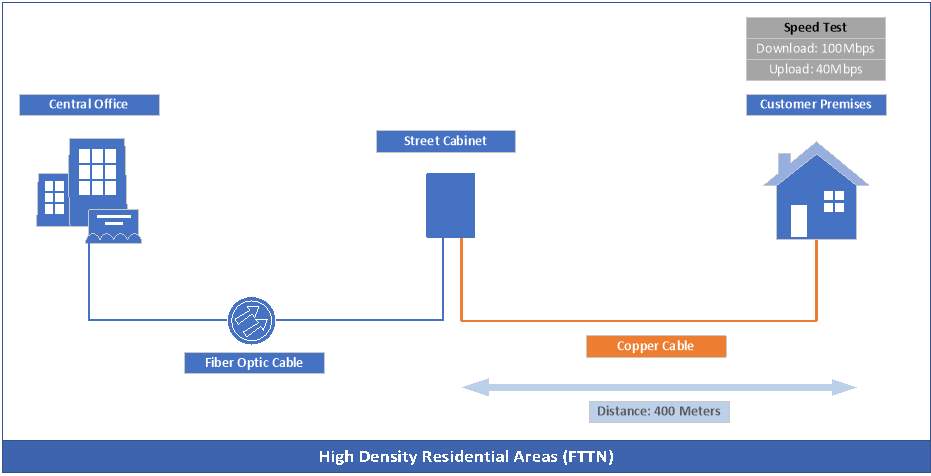
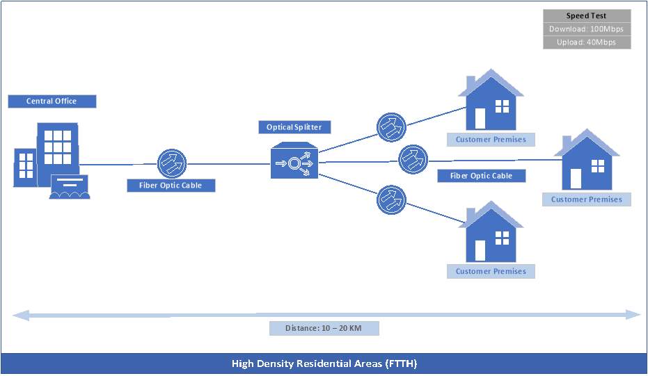
4.1.1 High Density Residential Areas
We have two versions of Access network designs for the High Density Residentials areas. These proposed designed varies on the current infrastructure in ways such as:
- If the user premises are very old and optic fiber cannot be implemented within the premises whilst taking cost into consideration then Fiber to the Node would be the best suitable approach.
Fiber to the Node (FTTN) connection is used in situations where there is an existing copper line to the premises whilst providing optic fiber cable to the cabinet which is commonly <500m away from the customer premises.
FTTN uses VDSL2 modem to transmit data over the copper line. In terms of the bandwidth speed it varies on the distance from the node to the premises. Download speeds of 100Mbps can be achieved by having the node 400m away and speed of up 60Mpbs if the node is more than 700m from the cabinet. These speeds can be altered also by the bandwidth package that the user chooses from the ISP, hence does not guaranteed the speeds at 100%. We must also be mindful that speed may vary depending on the distance from the cabinet, and the quality of the links used.
- This approach only applies to urban areas or newly developing areas. This allows us to run optic fiber cables for the first time in these premises, which FTTH is the best approach.
Fiber to the Home (FTTH) can be implemented with the help of Passive Optical Network (PON) as it brings the fiber cabling and signals all way to the premises. This is achieved by using an Optical Splitter which is responsible for distributing the signal. In order for this technology to be functioning and implemented correctly, we must ensure total distance from the exchange to the customer locations (<20Km). This technology is shared as it is point-to-multiple-point network which means all users sharing the bandwidth. Being mindful of congestion is vital when implementing this technology. PON’s can share across 32 subscribers and is the most cost effective and fasted method for these sorts of areas.
4.1.2 Advantages & Disadvantages of HDRA Technology
The advantages and disadvantages of FTTN are:
Advantages:
- Speed Enhancement – The speed is much quick than using the previous legacy networks, as optic fiber is much quicker than copper.
- Available for old premises – Since we don’t have to implement any new cables in the premises, this allows older premises to take advantage of the optic fiber.
- Cost Efficient – Much cost effective than FTTP.
Disadvantages:
- Speed – Compared to FTTP, the speeds are significant slow.
- Old Technology – Having to use copper technology, which is old and is not best-practice.
The advantages and disadvantages of FTTH are:
Advantages:
- High Speed Bandwidth– Since the entire connection is made out of optical fiber, users can take full advantage of the rapid speeds.
- Latest Technology – Fully optic fiber cable the entire way.
Disadvantages:
- Cost – It is expensive to run optic dedicate technology compared to the rest.
- Implementation – Optic fiber connections are sensitive and difficult to handle. Alignment of the cabling is also difficult
- Bending – Fiber cannot be bent very tightly like copper, because this can cause high bend losses affecting the entire technology delivery service.
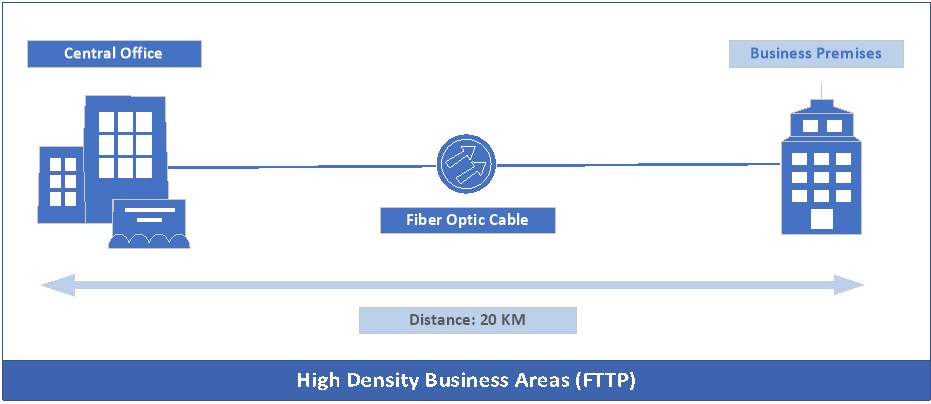
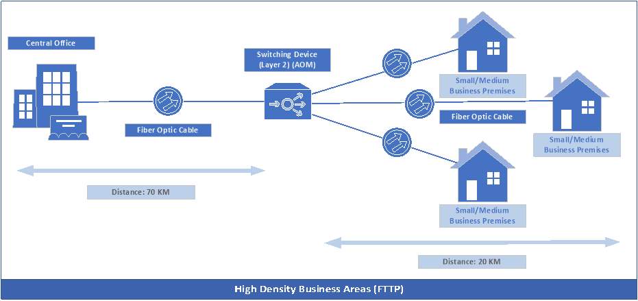
4.1.4 High Density Business Areas
We also have two versions of Access network designs for the High Density Business areas such as:
- Dedicated Bandwidth – FTTP is among the simplest fiber networks to deploy, as fiber is directly connected to the central office and also connects directly to the premises. This allows customer to receive dedicate bandwidth. This is usually expensive and organizations/enterprises go for this guaranteed solution. The central office must be <20Km in order to achieve a high standard of quality service.
- Shared Bandwidth – This method of deployment is mainly for small/medium business who don’t have large requirements by implementing Fiber to the Premises (FTTP) whilst using Active Optical Network (AON) to share the allocated bandwidth amongst multiple users. The AON has a PTP structure meaning that users will obtain a dedicated fiber optical line terminated on a optical concentrator. In terms of the signal it achieves distribution through Layer 2 equipment. This method of shared bandwidth can support a greater distance from the central office up to 70km, and 20km from the switching to the premises.
4.1.2 Advantages & Disadvantages of HDBA Technology
The advantages and disadvantages for HDBA are as follow:
Advantages:
- High Speed Bandwidth– Since the entire connection is made out of optical fiber, users can take full advantage of the rapid speeds.
- Latest Technology – Fully optic fiber cable the entire way.
- Scalable – This type of technology allows the business to grow and not having to worry about internet speeds for all users as they can reach 1Gbps.
Disadvantages:
- Cost – It is expensive to run optic dedicate technology compared to the rest.
- Implementation – Optic fiber connections are sensitive and difficult to handle. Alignment of the cabling is also difficult
- Bending – Fiber cannot be bent very tightly like copper, because this can cause high bend losses affecting the entire technology delivery service.
4.2 Wireless Access
4.2.1 Low Density Residential/Business Areas
In terms of providing connectivity to the Low Density Residentials/Business areas we proposed in deploying WiMAX. We chose this technology due to multiple reasons, the main reason is the cost, it is too high to deploy optic fiber in low population areas as the return investment isn’t there.
Worldwide Interoperability for Microwave Access is a wireless broadband technology similar to WiFi but at a much higher speed over great distances and for greater number of users. It works by pointing out a line-of-sign to other WiMax transmitters to provide connectivity around the designated area. It is based on IEEE 802.16 wireless broadband standard.
4.2.2 Advantages & Disadvantages of WiMAX Technology
The advantages and disadvantages for HDBA are as follow:
Advantages:
- Accessibility – It has the capacity to serve a large number of users and devices.
- 4G Compatibility – It delivers high speed internet service.
- Large Bandwidth – Its mechanism is design in ways that the radio platform infrastructure allows a greater use of bandwidth.
- Implementation – It is short and simple to set up.
Disadvantages:
- Cost – The technology is extremely expensive but also since it only supports 4G the cost of the monthly subscription can be costly.
- Installation – Even thought the installation is simple, the cost of installation is really high.
- Line of Sight – This technology is required, which can create issues if not done correctly or if obstacles appear.
4.3 Remote Areas
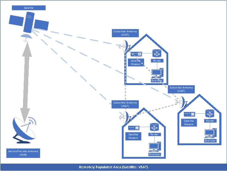
4.3.1 Remote Populated Areas
In terms of providing connectivity to the Remote Rural areas we proposed in deploying Satellites. Figuring out what technology to deploy in this unpopulated was extremely complex as cost needs to be carefully considered but also the future growth of the geographical area. A key point to consider is the returned investment, as regardless what technology we use, we would face a loss.
After careful consideration, we decided to deploy Satellite using VSAT system. VSAT stands for Very Small-Aperture Transceiver, which contains numerous earth stations in order to achieve two-way communication with a Master Earth Station through geostationary satellites. We would also be deploying a Mesh Topology due to its single hop functions and redundancy options.
The Geostationary satellites are located in the equator and orbit every 24 hours hence it appears stationary to anyone observing. Each satellite can come 120 degrees, making up 3 geostationary satellites to cover the entire Earth.
4.3.2 Advantages & Disadvantages of Satellite: VSAT Technology
The advantages and disadvantages for HDBA are as follow:
Advantages:
- Access in Remote Location – As a single geostationary satellite can cover 33% of the earth, this allows connectivity services to rural areas but as well as ships and coastal regions within the coverage area.
- QoS – This technology supports QoS and Layer 2 prioritization policies can be applied across the satellite link, including bandwidth allocation.
- Highly Scalable – Effortlessly and cost effectively scaled to house across the sphere.
- Rapid Deployment – Setting up the end-user can take hours whilst equipment at your disposal.
- Reliable – Satellite access link are extremely reliable, with known up time of 99.5%.
Disadvantages:
- Cost – The technology is extremely expensive to initiate but also the recurring monthly cost is high compared to urban broadband superscription.
- Latencies – It offers high latencies due to the distance it must travel.
- Weather – The rain can affect the performance of the satellite but also weaken the signal.
4.4 Mobile Wireless Access
4.4.1 3GPP 4G
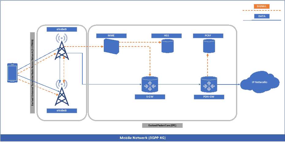
Providing a high-speed wireless internet solution for the entire population of Australia for the wireless mobile devices is vital to ensure that end-users can also access their services on the go. In this proposed design the type of mobile network we decided to deploy is 3GPP 4G, due to numerous reasons, but mainly because it can provide Quality of service. The 4G network uses LTE technology, however it has evolved to LTE -Advanced Pro which can support over 1Gbps. The 4G networks is made up of numerous components such as:
- Orthogonal Frequency Division Multiple Access (OFDMA) – This is used for the downlink which is a high amount of bandwidth (single) which is split into multiple orthogonal subcarrier in order to support multiple users.
- Single Carrier-Frequency Division Multiple Access (SC-FDMA) – This is used for the uplink which uses the technology of OFDMA. Its functionality is to encode and modulate that occurs in a single carrier transmission.
- Evolved Universal Terrestrial Radio Access (E-UTRAN) – This technology is extremely simple as it is only composed of the eNodeB. eNobe B is an evolved version of Node B, which accomplishes 3G legacy functions for broadcast and signal over radio interfaces.
- Evolved Packet Core (EPC) – Is a framework providing converged voice and data on a 4G networks. It is split into 5 main functions;
- The Mobility Management Entity (MME) – Responsible for managing sessions and authentications. This function also tracks users across the network.
- The Home Subscriber Server (HSS) – Responsible for storing component and updates upon the user subscription information. Also responsible for generating security information from the use identity keys.
- The Serving Gateway (S-Gateway) – Responsible for acting as a gateway between the LTE network and Packet Data. Responsible for managing QoS and performing deep packet inspection for security.
- The Packet Data Network (PDN GW) – Similar to the Service Gateway, however it is responsible for routing packets to and from the PDN. The PDN GW also performs various functions such as packet filtering, policy control, evolved charging support.
- The Policy and Charging Rules Functions (PCRF) – Responsible for managing/supporting policies enforcement, QoS setting information and accounting rule information.
5.0 Quality of Service
Quality of Service is more important now than 5 years ago, due to the demands of the public but also due to the new inventions and advancements of technology. As IoT and watching videos are the main two growing factors, companies like Netflix, Spotify, Optus Sport are mainly responsible for this growth of demand. Live sport is also extremely responsible for the growth of video content, specially on portable devices that support numerous platforms for these services to be accessed on.
We gathered this data of demand from the annual Australian Communications and Media Authority Communication Report 2016-17 which key points are summarised in the Appendix section, which offers a graphical diagram outlining the demands of each service and target audience.
In simple form what Quality of Service is the mechanism that is used to control delays, bandwidth and packet loss in the network to ensure that you’re constantly getting quality, fast, reliable service. Below are the key features of QoS:
- Dedicated Bandwidth
- Congestion Management
- Congestion Avoidance
- Improved of Loss Characteristics
- Traffic Shaping
- Prioritization of Traffic
5.1 Differentiated Service
Differentiated Service also known as DiffServ Model is a framework that can manage different quality of services. Its functionality is to mark packets headers using the ToS byte by marking the first 3 bits with IP Precedence and 6 bits with IP DSCP. The value of the IP Precedence is part of the IP DSCP value though it is design not be same concurrently. IP DSCPT is compatible with the IP precedence bits due to its backward compatibility mechanism. IP Precedence has a maximum of 8 different IP precedence markings whilst IP DSCP has a maximum of 64 DSCP markings. These 8 values for IP Precedence are defined based on priority as 0 = Lowest to 7 = Highest priority.
6.0 Service and Network Management
6.1 Simple Network Management Protocol
Simple Network Management Protocol also known as SNMP is used to manage IP objects on an IP-based network. Its simple mechanism of poll/response where an SNMP server gathers information from sending poll request to the Management Information Base (MID) and waits for the response from the node.
The SNMP in made up of 3 versions; v1, v2c, v3. In this design we will be using version 3 as it supports MD5 or SHA encryptions guaranteeing your privacy and encryption using DES algorithm.
6.2 Remote Monitoring
Remote Monitoring (RMON) is a standard monitoring technique allowing networks monitors and console system to exchange information.
“The RMON MIB added much needed remote monitoring capability to the basic SNMP MIB; it allowed the network manager to view a LAN segment as a whole rather than as a collection of individual devices. [20]
Devices with the RMON MIB implemented behave like a network probe; passively recording traffic information that can in turn be retrieved via SNMP GET commands. [20]“
7.0 Appendix
All information for this section was copied from Australian Communications and Media Authority -Communication Report 2016-17. [16]
Key Highlights for 2016-17:
“The mobile phone is now the most popular and most frequently used device to go online. The shift to mobile phone-only for communication continues, with 6.67 million Australian adults having a mobile phone and no fixed-line telephone at home. The popularity of communications apps on mobile phones has also continued, with eight in 10 internet users having used an app to communicate.
Content use and, more specifically, demand for video content over the internet, is increasing, with 59 per cent of Australians having watched content online at June 2017. Service providers are responding by expanding platforms and services to meet their customers’ online needs. Australians continue to spend a majority of their viewing time watching broadcast television.”
From Internet of Things to internet of every thing
The IoT is moving mainstream. The year to June 2017 saws Australia’s telecommunications carriers makes firm commitments for network investments, technology trials and commercial deployments of IoT. Telstra announced plans to build a national IoT network in partnership with Ericsson. Vodafone completed a successful trial of Narrowband Internet of Things (NB-IoT) technology with utilities and technology partners, with plans to launch commercial services in Melbourne late in 2017. Optus completed its NB-IoT trial early in 2017 (a date for the launch of its services had not been announced at the time of publication).
The adoption of the IoT in Australia has grown rapidly, with the technology embraced across industries and locations—from smart bins in Bondi to monitoring water tanks on rural properties. Consumers have also adopted IoT technology, with an increased proportion of Australian adults connecting smart TVs to go online within the home.
Industry forecasts indicate that 29 billion devices will be connected worldwide by 2022, of which 18 billion will relate to IoT.
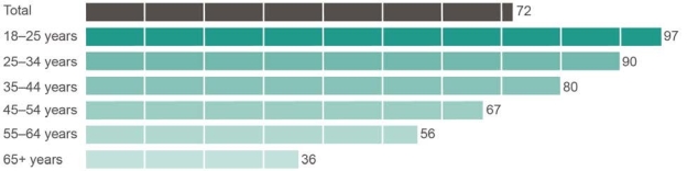
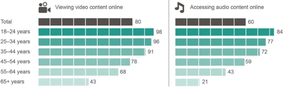 Australians accessing online video and audio content, by age, June 2017 (percentage)
Base: Australians aged 18 and over who accessed the internet.
Note: ‘Don’t know’ and ‘Prefer not to say’ responses are excluded from analysis. Source: ACMA-commissioned survey, June 2017.
 Social media use, by age, June 2017 (percentage)
Base: Australians aged 18 and over who accessed the internet.
Note: ‘Don’t know’ and ‘Prefer not to say’ responses are excluded from analysis. Source: ACMA-commissioned survey, June 2017. “
Communications apps
At June 2017, 88 per cent of Australian internet users had used an app to communicate via messages or voice or video calls in the last six months—using apps to send messages was the most popular (85 per cent). Just over four in 10 (42 per cent) did all three.
Use of communications apps, by activity, June 2017(percentage)
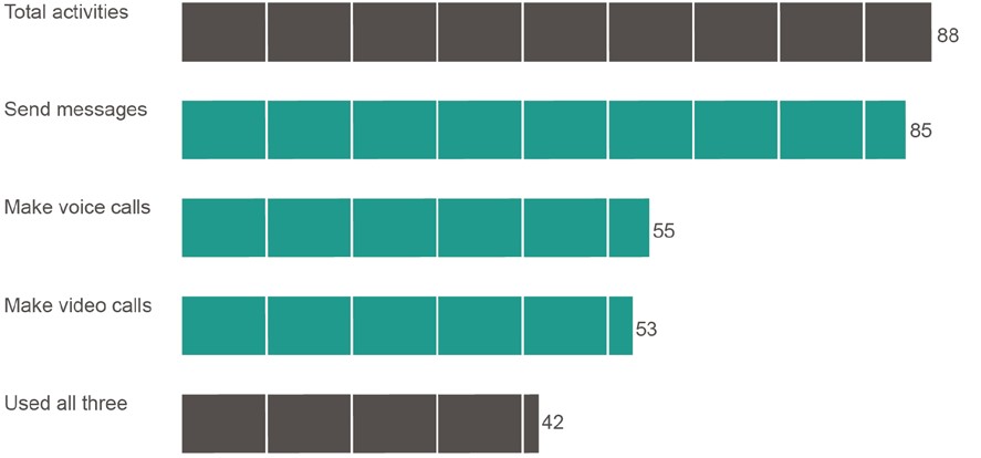
Base: Australians aged 18 and over who accessed the internet.
Note: ‘Don’t know’ and ‘Prefer not to say’ responses are excluded from analysis. Source: ACMA-commissioned survey, June 2017.
Younger Australians were the most active users of communications apps, with 98 per cent of those aged 18–24 using an app to send messages (Figure 2.12). There was also high use among those aged 25–34 (95 per cent) and 35–44 year olds (88 per cent), dropping to 61 per cent for those aged 65 and over.
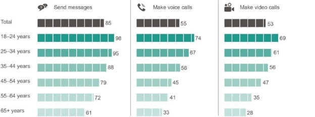 Use of communications apps, by activity and age, June 2017 (percentage)
Base: Australians aged 18 and over who accessed the internet.
Note: ‘Don’t know’ and ‘Prefer not to say’ responses are excluded from analysis. Source: ACMA-commissioned survey, June 2017.
“
8.0 Conclusion
In this Next Generation Telecommunication Design for the Australian Communication Network, we proposed and designed a network that can provide Internet solutions regardless of the location or device through taking numerous factors into consideration such as;
- Population
- Bandwidth Demand
- Bandwidth Speed
- Geographical Location
- Residential & Business Requirements
- Future Growth
All these requirements are vital in order to determined what technology must be used, but also the quantity. Scalability and QoS is also an important factor as what are the point of having a network when it’s not reliable.
Overall, we covered the Design Overview which outlines the entire network diagram in a brief form whilst outlining the benefits associated for the entire design. We also cover the Core Layer & Access Layer technologies, its pros and cons, network diagram which enables us to have a detailed fundamental understanding of the deployment.
We divided the Access layer into 4 categories; Wired Access, Wireless Access, Remote Areas, Mobile Wireless Access which all provide different type of technology, whilst all operating together in order to provide connectivity through the Aggregation layer.
Quality of Service and Service and Network Management is also outlined in this report, to ensure the quality of the service is achieved whilst managing the network accordingly through the implementation of Remote Access.
Through this design, we can achieve a reliable, scalable, quality telecommunication design, that will cover the demand for the entire of Australia but also for the future growth of Australia.
9.0 References
[1] Worldometers.info. (2018). Australia Population (2018) – Worldometers. [online] Available at: https://www.worldometers.info/world-population/australia-population/ [Accessed 15 Oct. 2018].
[2] 9tut.com. (2018). CCNA Training. [online] Available at: https://www.9tut.com/ [Accessed 15 Oct. 2018].
[3] SearchNetworking. (2018). Core, Distribution and Access. [online] Available at: https://searchnetworking.techtarget.com/tip/Core-Distribution-and-Access [Accessed 15 Oct. 2018].
[4] Don Jacob, T. (2018). A Quick Start To MPLS Fundamentals | Packet Design. [online] Packet Design. Available at: https://www.packetdesign.com/blog/quick-start-mpls-fundamentals/ [Accessed 15 Oct. 2018].
[5] Aussiebroadband.com.au. (2018). FTTP vs FTTN vs FTTC: Connections to the National Broadband Network explained | Aussie Broadband. [online] Available at: https://www.aussiebroadband.com.au/blog/fttp-vs-fttn-connections-national-broadband-network-explained/ [Accessed 15 Oct. 2018].
[6] Garden, H. (2018). How WiMAX Works. [online] HowStuffWorks. Available at: https://computer.howstuffworks.com/wimax1.htm [Accessed 15 Oct. 2018].
[7] King, J. (2018). Key features of Next Generation Networks. [online] Bigair.com.au. Available at: https://www.bigair.com.au/blog/key-features-of-next-generation-networks [Accessed 15 Oct. 2018].
[8] Whistleout.com.au. (2018). NBN Fibre to the Premises: Everything you need to know. [online] Available at: https://www.whistleout.com.au/Broadband/Guides/nbn-fttp-everything-you-need-to-know [Accessed 15 Oct. 2018].
[9] Slideshare.net. (2018). NGN Next Generation Network. [online] Available at: https://www.slideshare.net/HavarBathaee/ngn-nextgeneration20network [Accessed 15 Oct. 2018].
[10] En.wikipedia.org. (2018). Satellite link. [online] Available at: https://en.wikipedia.org/wiki/Satellite_link [Accessed 15 Oct. 2018].
[11] Scutt, D. (2018). This map shows population density across Australia. [online] Business Insider Australia. Available at: https://www.businessinsider.com.au/this-map-shows-population-density-across-australia-2017-7 [Accessed 15 Oct. 2018].
[12] Google.com. (2018). simpson desert on a map – Google Search. [online] Available at: https://www.google.com/search?sa=G&hl=en-AU&q=simpson+desert+on+a+map&tbm=isch&tbs=simg:CAQSlwEJMgj0lpIzAlwaiwELEKjU2AQaBAgVCAsMCxCwjKcIGmIKYAgDEijBB9YI_1RLYCcYHvwfNB8IHxQfRApY57z7oP-c_15T_1kP6Ir4z_1uPvI-GjCs8_1r-3dqTPMUU6qCkQAYFFJbRwE8Ax2lFDmVOYO2oQacSoWfTFYe6J6vtQFGOCjcgBAwLEI6u_1ggaCgoICAESBHbMXeYM,isz:l&ved=0ahUKEwjj48X_yYfeAhUCa94KHd7PDJYQ2A4ILigE&biw=2144&bih=1054#imgrc=D0tGzThPwyqz4M: [Accessed 15 Oct. 2018].
[13] SearchTelecom. (2018). What is dense wavelength division multiplexing (DWDM)? – Definition from WhatIs.com. [online] Available at: https://searchtelecom.techtarget.com/definition/dense-wavelength-division-multiplexing [Accessed 15 Oct. 2018].
[14] SearchNetworking. (2018). What is Multiprotocol Label Switching (MPLS)? – Definition from WhatIs.com. [online] Available at: https://searchnetworking.techtarget.com/definition/Multiprotocol-Label-Switching-MPLS [Accessed 15 Oct. 2018].
[15] White, G. (2018). How Do Packets Get Around? | Understanding Networks and TCP/IP | InformIT. [online] Informit.com. Available at: http://www.informit.com/articles/article.aspx?p=131034&seqNum=5 [Accessed 15 Oct. 2018].
[16] Acma.gov.au. (2018). Australian Communication Report 2016-17. [online] Available at: https://www.acma.gov.au/-/media/Research-and-Analysis/Report/pdf/Communications-report-2016-17-pdf.pdf?la=en [Accessed 15 Oct. 2018].
[17] En.wikipedia.org. (2018). Differentiated services. [online] Available at: https://en.wikipedia.org/wiki/Differentiated_services [Accessed 15 Oct. 2018].
[18] The Pros and Cons of WiMAX. [online] Tom’s Guide. Available at: https://www.tomsguide.com/us/the-pros-and-cons-of-wimax,review-398.html [Accessed 15 Oct. 2018].
[19] Schriber, A. (2018). VSAT Defined: What is it and How Does It Work?. [online] Internet Access Guide. Available at: http://internet-access-guide.com/vsat-defined-what-is-it-and-how-does-it-work/ [Accessed 15 Oct. 2018].
[20] Icanovich, M. n.d., “HET729 Design and Management of Networks, Network Management”
Cite This Work
To export a reference to this article please select a referencing stye below:
Related Services
View all


Related Content
All TagsContent relating to: "Engineering"
Engineering is the application of scientific principles and mathematics to designing and building of structures, such as bridges or buildings, roads, machines etc. and includes a range of specialised fields.
Related Articles

DMCA / Removal Request
If you are the original writer of this dissertation and no longer wish to have your work published on the UKDiss.com website then please: