Simulating Blood Flow in Vessels Affected by an Aneurysm
Info: 8061 words (32 pages) Dissertation
Published: 24th Feb 2022
Tagged: NeurologyBiomedical Science
Abstract
This report advises a computational technique for simulating the flow profiles of laminar blood flow for Newtonian and Non-Newtonian cases in a blood vessel that has been affected by an aneurysm. Simulations were run for coiled and uncoiled cases, as well as a special case in which the aneurysm has been moved to the main vascular branch. In addition, simulations for turbulent flows for Reynolds numbers 20000, 30000, 40000, and 50000 were done in order to compare to the laminar cases. A grid independent geometry for the simulations was made using the CFD-ACE+ program and carried out in CFD-ACE. While the laminar case used an unstructured mesh, the turbulent cases used a structured boundary layer combined with unstructured mesh in order to better capture the turbulent flow characteristics and behaviours. Velocity, Pressure and wall shear stress profiles and data were collected and analyzed. The results showed that the Newtonian and Non-Newtonian cases had only slight differences due to the Blood Power Law taking into account the shear thinning nature of blood under varying strain rates and key areas for rupture of the aneurysm sac were identified. The special case, when compared to the base case, exhibited a lower maximum velocity but, due to the aneurysm area being part of the main branch, there was a large pressure inside the sac. Also, it was seen that for the turbulent cases, the pressure drops were much larger than those of the laminar cases due to the increase in flow velocity.
INTRODUCTION
Aneurysms can be found wherever there is weakness along blood vessel walls and are characterized by a thin-walled bulge along the wall’s outer lining. They are formed due to continuous blood flow stressing thinned portions of the vessel walls, which then causes the swelling into the characteristic, thin bulge [1]. Its most dangerous attribute, though, is that it is identified usually only when they rupture, which can lead to a serious condition known as a subarachnoid haemorrhage [2]. While all aneurysms are considered detrimental to one’s health, cerebral aneurysms are among those which are especially lethal. These are most often found near the branching point of arteries at the base of the brain and, if ruptured, can cause spontaneous intracranial bleeding [3]. The resulting subarachnoid haemorrhage may cause extensive brain damage and possibly death. Studies show that approximately 30% of these ruptures are immediately lethal and without proper treatment, an additional 30% will lead to death within just 4 weeks [4], [5].
Many techniques can be employed in order to treat this condition but the most widely used is endovascular coiling [6]. This procedure facilitates the blockage of blood flow into the aneurysm through the use of detachable platinum coils during a minimally invasive technique (does not require an incision in the skull for treatment) [6]. During the procedure, a catheter is passed through the groin up into the artery affected by the aneurysm while observing the path followed using an X-ray. Once the catheter arrives at the location, multiple platinum coils are fed into the aneurysm. Once the aneurysm is filled, thrombosis is induced, which causes blood clotting in the aneurysm and isolates it from normal blood circulation, thereby preventing further bleeding or growth of the aneurysm [3]. A depiction of the end result of the procedure can be seen in Fig. 1 below [7].
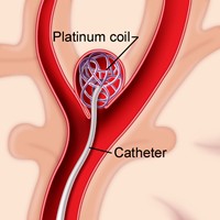
Figure 1 Showing Endovascular Coiling as Treatment for an Aneurysm [7]
To help better understand the parameters behind blood flow in vessels that contain an aneurysm, blood flow dynamics plays a vital role. These parameters usually involve pressure, wall shear stress, velocity and residence time [8]. While these parameters can be used to understand aneurysm growth and rupture, they can also be used to assist in treatments, such as endovascular therapy using coiling [9], [10]. It is also worth considering the type of fluid flow. Fluid flow has a high dependency on the viscosity of the fluid and these fluids can be either Newtonian or Non-Newtonian. Blood is a Non-Newtonian fluid, meaning that its viscosity is not constant and in actuality depends on its shear rate of flow. Blood exhibits shear thinning behaviour and has the ability to reduce its viscosity with varying vessel diameter and shear stress, allowing it to reach even the smallest of capillaries [11]. However, when the blood cell size is close to the diameter of the capillary, the behaviour is reversed. Usually, the relationship is non-linear and if not accounted for in simulations can give inaccurate results. Newtonian fluid particles, however, are not orientated by flow and have a linear dependency with shear rate with the velocity gradient being perpendicular to the plane of shear. The constant of proportionality for this relationship is defined as the absolute viscosity and is denoted by µ or η.
In recent times, computational fluid dynamic (CFD) programs have been used to simulate the above-mentioned parameters for different cases of haemodynamics in the human body. An article published by Shishir et al. [1] gives an insight into blood flow dynamics in saccular cerebral aneurysms using ANSYS CFD FLUENT simulations. The study involved analysing laminar flow for incompressible Newtonian fluid by computing a 3D Navier-Stokes equation for the flow-field. The researchers used a tetrahedral mesh for their model with a very large number of small (0.00025m) elements (600000-1200000), achieving as much refinement as possible to obtain accurate results for the study. The simulations concerned aneurysms with both a circular and elliptical neck of different sizes and how the flows would be depicted in those areas for four different models of each neck. The results showed that the rupture risk of an aneurysm increases with the size of its neck and the parameters velocity, pressure and wall shear stress increase with neck size [1].
Another study using CFD in haemodynamic cases was carried out by Mitsos et al. [12]. This case involved haemodynamic simulation of aneurysm coiling using a porous medium-based method for the simulation. The researchers used data obtained from an angiogram of a ruptured aneurysm to create a geometric model and simulate haemodynamics caused by coil embolization. The results showed that there were dramatic changes in the blood flow after the first coil was introduced and the patterns became much less vorticial in the aneurysm sac and the pressure exerted on the wall due to blood flow was gradually reduced [12], which could inhibit aneurysm growth and rupture.
For this report, the objectives involved simulating haemodynamics in a blood vessel that contained an aneurysm at the branching point of that vessel. All simulations were run using the CFD-ACE+ program. The geometry created was 2D and simplified when compared to its 3D counterpart. After achieving grid independence for the base case (Uncoiled Newtonian), we used this model to investigate cases for both Newtonian and Non-Newtonian blood flow in coiled and uncoiled cases for laminar flow. When modelling for the Non-Newtonian cases, we use the Blood Power Law, which helps to model the particulate nature of blood in the simulation. In addition, we investigated the case of turbulent flow in the aneurysm for Reynolds numbers of 20000, 30000, 40000, and 50000 using a k-ε standard turbulence model. Finally, we were tasked with investigating a case beyond the ones detailed in the brief. In this report, I will be presenting a haemodynamic model of a blood vessel in which the aneurysm has been created along the main vascular branch instead of at the branching point.
METHODS
A. Overview
Endovascular Coiling involves the use of a catheter inserted into the artery at the groin, which is then fed through various arteries and monitored via X-ray guidance in order to arrive at the aneurysm’s location. Multiple platinum coils are then fed through the catheter and coiled in the aneurysm sac. These coils are manufactured with an intent of them forming a sphere with a pre-specified diameter upon their release into the sac. The multitude of coils released form a miniature, uniform network which inhibits blood flow in the aneurysm and facilitates thrombosis due to the reduced blood flow [3]. The stagnated blood will coagulate on the spiralled coils and fill the entire aneurysm gradually in order to prevent the blood from clotting too quickly and not allowing a further number of coils to be released into the sac. The clotting is usually prevented through the introduction of anticoagulants during the implementation of the coils.
In order to model the blood vessel properly, it was split into two sections: the main branches of blood flow and the aneurysm itself. For the uncoiled models (Fig 2a), the fluid was simulated as uniform with no porosity while for the coiled models (which separated the fluids by a curved line (see Fig. 2b)) had a pure fluid for the main branches of the blood vessel and a porous fluid medium for the fluid in the aneurysm.

Figures 2a, 2b and 2c Showing Uncoiled (Left), Coiled (Centre) and Turbulent (Right) Meshes Respectively
B. Modelling the Cerebral Aneurysm in CFD-ACE+
In order to carry out our simulations for blood flow in the model, we first had to construct the geometry using CFD-GEOM. The main branch had length 10 mm and a width of 1.5 mm. The length of the upper and lower branches’ outer walls were also 10 mm with a width of 1 mm. The aneurysm was modelled as an ellipse with major and minor radii 4.5 mm and 3.5 mm respectively. The geometry of the aneurysm was much more simplified than it would be in reality, emphasized by the fact that it was a 2D model. An unstructured triangular mesh as used in order to discretize the domain of the model’s surface (Fig. 2a, 2b). These meshes are mostly used for irregular shapes that are difficult to model with a structured mesh. The unstructured triangular mesh offers a much quicker solution, meshing irregular geometry fairly quickly. However, the construction for both the laminar and turbulent cases were slightly different. While the laminar geometries had only the unstructured mesh, the turbulent meshes were subject to a combination of unstructured meshing and a boundary layer meshing criterion (Fig. 2c) in order to capture the flow present near the walls of the model and properly simulate the turbulent fluctuations of the blood flow for the high Reynolds numbers.
In addition, the simulations could not be run without first achieving a form of grid independence for the laminar cases. After a certain number of elements in the grid, there is little change between the results of the simulations. Grid independence was run for the base case scenario and, using the number of elements found for that independence within a a percentage error of 1% and simulations were run.
The geometry was divided into two using a curved line which connected the aneurysm (Fig 2b). This represented the coiled area of the model and was set to a be a porous medium in order to simulate the prevention of flow into the aneurysm sac.
For this study, we were interested in the blood flow velocity, the pressure drops across the aneurysm, the wall shear stresses and the strain rate for all laminar cases. For the turbulent cases, we were interested in comparing the flow characteristics to the laminar case and observing the pressure drops for the simulations. The parameters investigated were those which would have an effect on the haemodynamics and its behaviour in the blood vessel for both coiled and uncoiled cases.
For the numerical solution of the blood flow for these simulations, we used the CFD-ACE+ package by the ESI Group (Paris, France). The model uses a combination of momentum conservation equations, mass conservation equations and flow module theory in order to solve the many iterations for the simulations. These shall be discussed in the next section.
C. Coil Modelling via Porous Media, Fluid Flow Module Theory, Mass Conservation, Blood Power Law and Momentum Conservation for Laminar and Turbulent Cases
In order to proceed with the simulations, mathematical models need to be employed to solve the various equations that take part in the CFD calculations. As stated previously, the system with the coils inserted has the fluid modelled in the sac as a porous medium. The mathematical models that are used to illustrate transport through a porous medium depends primarily on the porosity of the medium and the inverse of its permeability, as well as the drag factor along the porous flow. This porosity is given by the following expression
φ=1- ∑i=1NCVc,iVan (1)
where
Van= (4/3)
π(a/2)(b/2)(c/2).
NC represents the number of coils placed in the aneurysm section of the model,
Vc,i is the volume of the ith coil, and
Van is the total volume of the aneurysm [3].
The permeability of the fluid is represented as k and is a measure of the conductivity of the fluid through the porous medium and the surface area to volume ratio of the porous matrix. In order to calculate the permeability, we need to incorporate Kozeny’s capillary theory, which approximates the porous medium as a layer of solid material with straight parallel tubes having a constant cross-sectional shape intersecting the sample [13]. The expression [3] is given as
k= φ3cS2 (2)
Where c is the Kozeny coefficient depending on the cross-section for capillaries
c = 2 for circular cylinders
S is the ratio internal surface area of the pores to the total volume of the aneurysm.
For this model, the parameters set for porosity and permeability were 0.8 and 1×10⁻⁸ m2. This means that there is a packing density of 20% for the aneurysm when the coil is released.
The governing equations used for the Flow Module Theory in CFD-ACE+ originate from the conservation laws of physics for flow, i.e., conservation of mass and conservation of momentum. For the porous part of the model geometry, we consider first the mass conservation equation which is given by
∂ρ∂t+ ∇∙ρV⃗=0 (3)
And states that the flow of mass into a controlled volume system is equal to the flow of mass out of that same system.
Using the mass conservation law, we can multiply by the velocity in all directions and obtain equations for the conservation of momentum in the controlled volume system. The conservation of momentum states that the total momentum of objects before collision is equal to the total momentum of objects after collision. Applying this to fluid particles and the mass conservation equation [14] produces the expression
∂(ρU)∂t+ ∇∙ρV⃗u=∂-p+τxx∂x+∂τyx∂y+∂τzx∂z+SMz (4)
Where τ is the shear stress, p is pressure and SMz is the momentum source term.
The above equation is the general form of a Navier-Stokes Equation and can be rewritten for the other cartesian directions. However, these simulations are 2D so the latter equations are not used [3].
From the mass conservation equation, we can advance a step further by applying it to the porous part of the model geometry [14]
∂(φρ)∂t+ ∇∙ρV⃗U=0 (5)
Which then transforms into
∂(φρ)∂t+ ∇∙ρV⃗U= -φ∇P+ ∇φτ++ φB – φ2μkU- φ3CDρkjUU (6)
Where P is the pressure of the fluid that has density ρ and dynamic viscosity μ. The fluid flows with a velocity vector U, has a shear stress tensor of τ with a body force B acting as a momentum source. It should be established that as φ 1 and as k ∞, the standard Navier-Stokes equations which correspond to pure fluid regions are recovered [14].
CD represents the drag factor along the porous flow which can be calculated first determining Reynolds number using equation 7 below and using a standard CD vs Re diagram.
Re= dUaveρμ (7)
Note that this is assuming that the local flow is perpendicular to a cylinder of infinite length.
Unlike the Newtonian cases, the Non-Newtonian case brings the Blood Power Law into play. Due to blood being Non-Newtonian in nature, it would be accurate to model the fluid flow as such. The Blood Power Law takes into account the particulate nature of blood and its very important ability to be reduce its viscosity as a function of vessel diameter and shear stress. The model is given by the following equation [11]
μ=λγn-1 (8)
Where
λγ=μ∞+∆μ∙exp-1+γαexp-bγ (9)
And
nγ=n∞+∆n∙exp-1+γcexp-dγ (10)
Where γ is the local calculated shear stress, λ is the consistency constant, μ∞= 0.035 and is the limiting (Newtonian) viscosity, ∆μ=50, a = 50, b = 3, c = 50 and d = 4. All given values are the default set in CFD-ACE+.
For turbulent cases, we have to bring a few extra equations into play and a model specific to turbulence called the k-ε model. It is a 2-Equation differential and can be used to express the turbulent viscosity as a function of turbulent kinetic energy k, and dissipation rate ε. The equations [14] for each respectively are given below
∂(ρk)∂t+ ∂(ρujk)∂xj=∂∂xjµtσk∂k∂xj+Sk (11)
And
∂(ρε)∂t+ ∂(ρujε)∂xj=∂∂xjµtσε∂ε∂xj+Sε (12)
Where µ is the dynamic viscosity.
We also have to consider that for turbulence modelling, we need to incorporate boundary layer meshing in order to facilitate computations for the near-wall flow characteristics for turbulence. For this scenario, the initial flow at the wall is laminar but quickly transforms to turbulent within a very fine layer. Hence, the boundary layer meshing is essential to capture this phenomenon. We can use k-ε model to calculate the required boundary layer thickness to facilitate this capture through the following equations [14]
Uτ= τw/ρ (13)
y+=yUτ/ν (14)
Where y+ is the location of the first computational node from the wall, ν is the kinematic viscosity, Uτ is the friction velocity, τw is the wall shear stress and y is an arbitrary height perpendicular to the model wall. However, y+ is calculated by CFD-ACE+ during simulations and can be found as a result in CFD-VIEW.
RESULTS AND DISCUSSION
A. Overview
The results shown for this report are shown in the following order:
- Grid independence for the base case (Uncoiled Newtonian Laminar flow)
- The comparison of flow for both coiled and uncoiled cases for Newtonian and Non-Newtonian Laminar blood flow
- A comparison of the Special Case to the Base Case for Newtonian fluid flow
- Turbulent flow for Reynolds numbers 20000, 30000, 40000 and 50000.
These results were taken for the following parameters:
1. Blood mass density,
ρblood= 1060 kg/m3
2. Constant (Dynamic) Viscosity,
μDynamic=0.00357kgms
3. Inlet Velocity for base case,
Vinlet= 0.27 m/s
For this paper, the porous area is defined as the area to the right of the curved line which separates the geometry into the pure and porous areas.
B. Grid Independence of Base Case
Grid Independence (or mesh convergence) is the process by which a mesh is refined and the results compared until there is insignificant discrepancy between the last mesh and its previous result. Since the geometry of the model was irregular, it was decided that we use an unstructured triangular mesh. Meshes of 10201, 12293, 14047, 16384, 18143 and 19924 elements were used in this process. We used the data extracted for velocity magnitude across the horizontal line probe shown in Fig. 3b. Examples of the velocity profiles for these meshes can be seen below in Figs 3a-3b.
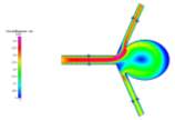
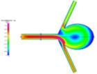
Figures 3a and 3b Showing the Change in Direction for Different Mesh Refinements for Laminar Convergence Testing
We can see that for each further mesh refinement, there is a change in flow direction. For a symmetric model such as this, one would expect the flow to follow suit. However, due to the unstructured nature of the mesh, the elements may be denser in some areas, which may influence the visualization that results from running the simulations. Fortunately, this effect does not have an impact on the overall results and can be overcome by simply using a structured mesh for the simulation.
From the results shown in Graph 1 below, we can see the plots of velocity magnitude curves for each mesh and how they arrive at convergence. The lowest percentage difference between the magnitudes was measured to be 0.763892% between the final two meshes, thus converging at 19924 elements.
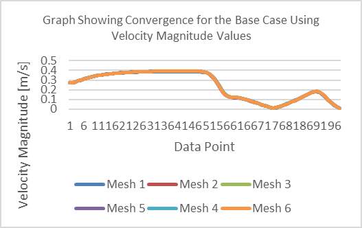
Graph 1 Showing Convergence for the Base Case Using Velocity Magnitude Values
Grid independence has paramount significance when running simulations in CFD as we can save computational power and time using the minimum number elements without needing any further refinement of the mesh.
In the following section, we used the converged mesh to carry out the simulations for our four cases and the special case.


Fig 5a and 5b Showing differences in Strain Rate and Velocity for Newtonian (Left) and Non-Newtonian (Right) Simulations
C. Comparison of Newtonian and Non-Newtonian Flow for Coiled and Uncoiled Cases
For this report, the laminar cases we were tasked with investigating were:
- Uncoiled Newtonian
- Uncoiled Non-Newtonian
- Coiled Newtonian
- Coiled Non-Newtonian
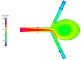
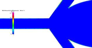
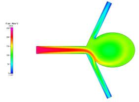
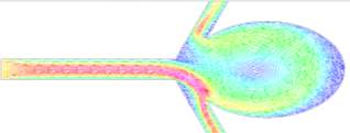
Each case was done for laminar flow and the data for velocity magnitude, total pressure and wall shear stress magnitude were extracted from their respective profiles and compared. The profiles can be seen in Figs. 4a-4c, 6a-6c, 7a-7c and 8a-8c for the respective data sets of each case. Figs 8a and 8b show the general vector profiles for the velocities for the coiled and uncoiled cases.
(a) 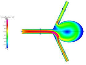
(a) 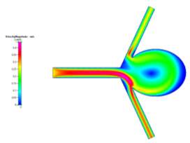
(b)
(b)

(c)
(c)
Figures 6a, 6b and 6c Showing Profiles for Uncoiled Non-Newtonian Case
Figures 4a, 4b and 4c Showing Profiles for Uncoiled Newtonian Case
For both the Newtonian and Non-Newtonian flows for the uncoiled case (Figs 4a-4c and 6a-6c), we see a steady flow of velocity through the inlet which then deviates to the lower outlet of the model. This flow then impacts the sharp corner of the aneurysm sac, causing some fluid flow to diverge and recirculate around the inside of the aneurysm to the upper outlet, while the remaining fluid continues flowing to the lower outlet. We can also observe that immediately after leaving the main vascular branch, there is an increase in velocity due to the fluid flowing around one of the corners. For the Non-Newtonian, the fluid velocity is slightly lower than the Newtonian. This may be a result of the Blood Power Law coming into play. When exiting the main branch, there is a slightly lower strain rate on the fluid, which means that the blood has a higher viscosity due to its shear thinning property. This means that its velocity might have been slightly lower than that of the Newtonian case. Even though there is a high strain rate at the walls of the vascular branches, there is a no slip boundary condition applied, which means that there will be zero velocity at the walls (See Fig 5a-5b).
In addition, we see that due to the recirculation, there is a small vortex created at the centre of the aneurysm and also near the sharp corner at the upper junction between the upper branch and the aneurysm neck. From the wall shear stress profile, we can see that at these neck areas, there are high shear stresses (especially on the lower corner due to the high velocity fluid flow), which are key areas to observe in aneurysm sacs as these are where ruptures can occur more easily.
(a)
(b)
(c)
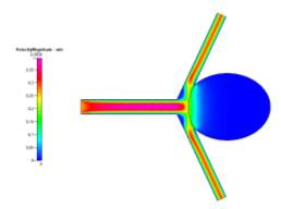
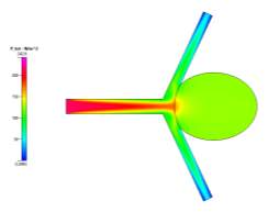
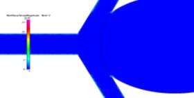
Figure 7a, 7b and 7c Showing Profiles for Coiled Newtonian Case
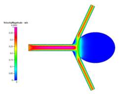
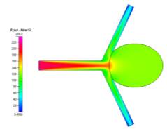
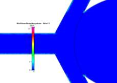
In contrast to the uncoiled cases, the coiled profiles show a completely different fluid flow. The profiles (shown in Figs 7a-7c and 8a-8c for velocity, pressure and wall shear stress respectively) show a fully developed blood flow along the main vascular branch, which then proceeds to impact the coiled area. This area, having been set with a porosity of 0.8, prevents fluid from entering the aneurysm, fully simulating the reality of the endovascular coil treatment. Some fluid does make its way into the sac but its velocity and resulting pressure and shear stress could be considered benign to the victim of the aneurysm. On the shear stress profiles in both Newtonian and Non-Newtonian coiled cases, the shear on the sharp corners of the aneurysm have been dramatically reduced due to the fluid flow being redirected away from the aneurysm and into its proper channels towards the outlet. The velocity profile is much more symmetric and is characteristic of the usual blood flow. However, small vortices are created where the main branch opens up to the branching vessels.
(a)
(b)
(c)
Figure 8a, 8b and 8c Showing Profiles for Coiled Non-Newtonian Case
These are created due to the pressure difference from the faster flow of fluid around the sharp corners of the main branch into the outlet. However, the fluid velocity is quite slow and does not cause high shear stresses on the walls.
We also see that for the pressure profiles, the uncoiled case shows a relatively high pressure in the aneurysm sac as a result of the recirculation of fluid flow inside. This is very dangerous, in reality, it can cause the aneurysm to grow and rupture if the pressure becomes too high. The coil prevents this pressure from entering the aneurysm and facilitating growth since it blocks and causes the fluid to flow to the desired channels. These can be seen clearly in the above pressure profiles.
One of the most important things to note is the wall shear stress plot on the walls of the aneurysm sac for the both the coiled and uncoiled cases. For all plots, we see that the shear stress in at a minimum at the far edge of the sac. For the coiled case, this is because there is hardly any fast fluid flow in the aneurysm due to the coil while in the uncoiled case there is a low fluid velocity at the far side of the aneurysm, making any shear stress minimal. The shear stresses at the same location for the uncoiled cases are very low also, but higher due to there being more fluid flow in the aneurysm. However, unlike the uncoiled cases, the coiled cases show drastic decreases in shear stress near the sharp corners of the aneurysm due to the fluid “jumping” over the area as it curves back towards the outlet after being redirected from the coiled area.
Comparing the Newtonian and Non-Newtonian cases can be very difficult as for each Newtonian case, their respective data and profiles are almost exactly alike. There is very little discrepancy between them which can be seen in the previous profiles. These small discrepancies can be accounted for by considering the Blood Power Law [11]. This law, as stated previously, helps to simulate the particulate nature of blood and, by extension, its ability to be shear thinning. This would, however slightly, account for the differences between the fluid flow and overall results of the simulations. One such example would be for the uncoiled Newtonian and Non-Newtonian cases, which showed a slight difference in the velocity of the fluid upon exiting the main vascular branch.
D. Comparison of the Special Case to the Base Case for Newtonian Fluid Flow
(c) 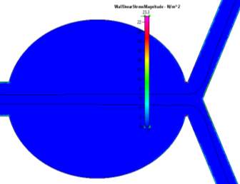
(a) 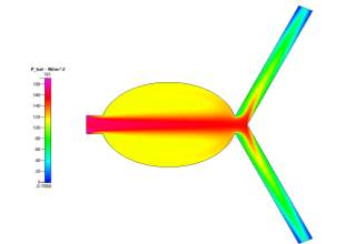
(d) 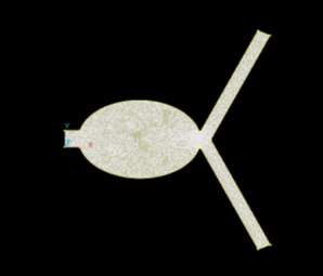
(b) 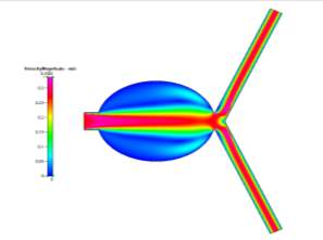
Figs 10a, 10b, 10c and 10d Showing the Mesh, Velocity Profile, Wall Shear Stress Profile and Pressure Profile for the Special Case
In order to further our understanding of the work, we were also tasked with simulating a special case – a unique scenario in which we could compare our results to the given objectives for this study. I chose to place the aneurysm in a different part of the blood vessel – in particular, the main branch (See Fig. 10a).

(a)
(b)
Figures 9a and 9b Showing Velocity Vector Plots for Uncoiled and Coiled Cases
Aneurysms generally form close to areas close to the point of branching out from two or multiple arteries [15]. It was decided to simulate the results of moving the aneurysm to the main branch and compare it to the base case – Uncoiled Newtonian. The results for the special case can be seen in Figs 10b-10d.
When comparing those profiles in Figs 10b-10d to those of the Uncoiled Newtonian Case, two observations to note immediately are the backflow that is present in the aneurysm sac due to the slight deviation of fluid flow form the main path and that the main flow velocity persists through the centre of the main branch before symmetrically diverging to the outlets. Even though there is a large area in the centre of the branch, the fluid, for the most part, does not deviate from its path as it is a fully developed steady-state solution. However, while there is still a small amount of flow in the aneurysm, it is very small compared to the main flow velocity. But it is worth mentioning that the pressure profile shows there to be a very high amount of pressure in the aneurysm itself due to the flow that does deviate slightly into the sac, which can cause the aneurysm to grow much larger than that of the base case. We can also see from the profiles that, while there is hardly any wall shear stress in the sac, there is a high amount present at the corners of where the sac meets the main vascular branch, which are areas to observe since a rupture may occur at those points.
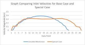
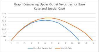
Graphs 2a and 2b Showing the Comparison of Inlet (left) and Upper Outlet (Right) Velocities of the Base Case to the those of the Special Case
To further develop this study, a recommendation would be that the size of the aneurysm be changed and the different profiles compared to better understand fluid flow in such scenarios. Another case could be carried out by changing the shape of the aneurysm’s neck, as was done in the research done by Shisir et al. [1].
E. The Turbulent Cases
The final objective of this study was to simulate cases for turbulent fluid flow. These simulations had to be run in a specific way in order to achieve the proper results. Firstly, the mesh needed to be a combination of an unstructured mesh and a boundary layer mesh in order to properly simulate the turbulent flow near the wall (see Fig 2c). Secondly, for the given Reynolds numbers, we had to calculate the corresponding velocity, the turbulent kinetic energy and the dissipation rate of the energy for a standard turbulence k-ε model. The reference length used for the model was given as the hydraulic diameter of the geometry rather than the given diameter (since the geometry was 2D, we had to treat it as we would a rectangular pipe with an infinite length in the z-direction). These values can be seen in Table 1 below.
| Speed | Kinetic Energy | Dissipation Rate | Reynold’s No. |
| 23 | 1.697911561 | 711.143224 | 19596.63866 |
| 34 | 3.364956523 | 1984.054803 | 30285.71429 |
| 45 | 5.495576421 | 4140.991656 | 40084.03361 |
| 57 | 8.311364899 | 7701.813587 | 50327.73109 |
Table 2 Showing Turbulent Modelling Parameters for Different Reynolds Numbers
The profiles for velocity magnitude and pressure for Re = 20000 were obtained from the results and can be seen in Figs 11a and 11b respectively. Each subsequent Reynolds number showed similar profiles, with higher magnitudes being the only difference.
For these high Reynolds numbers, the turbulent profiles highlight areas of blurred contours where the simulation has picked up small vortices in the fluid flow. This is characteristic of turbulence. However, the solution was a steady-state solution. In order to see the vortices, the simulation needs to be run as a time-dependent simulation in order to properly identify the transition from laminar to turbulence and capture the vorticial activity. You can see the transition from laminar to turbulent when looking at multiple x-cuts at close intervals of the inlet and an influx within the cut, which would be a sign of the turbulence developing in the flow. The areas where these blurred contours appeared were consistently in the same area – immediately after the fluid exited the main branch of flow. As the fluid flows around the sharp corners, the increase in speed due to shear thinning and the small rotation of the fluid flow caused by it flowing around the corner could have caused the vortices to appear at the edges of the faster flow.
For the velocity profile, we observe a gradual necking of the fluid flow due to the boundary layer mesh. This mesh is made up of three regions: a viscous sublayer, an inner region and then the outer region. As you move beyond each region, you can see drastic changes in the turbulent profile. The transition from laminar flow to fully turbulent flow happens almost immediately since the viscous sublayer is very thin (~0.005 units). As such, fully turbulent flow appears in the inner region and eddies form in the outer region [14].
Furthermore, for each increasing Reynolds number, we see a significant increase in pressure drop for each across the model (see Table 2).
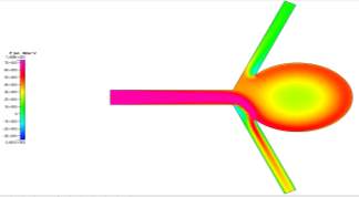
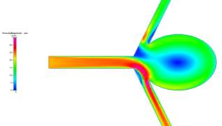
Figures 11a and 11b Showing the Velocity (Left) and Pressure (Right) Profiles for Re = 20000 Turbulent Flow

Table 3 Showing Pressure Drops for Turbulent (First four) and Laminar (Second four) Cases
Pressure is highly dependent on the velocity of the fluid and the density. For large increases in Reynolds numbers for the turbulent flows, there will be large increases in velocity, which will, as a result, increase the pressure across the model. However, the flow not being symmetric resulted in different pressure drops at the two outlets. The flow showed a consistent path towards the lower outlet, thus resulting in a larger pressure drop for the upper outlet.
While the turbulent computations had large pressure drops, the laminar cases had significantly smaller pressure drops due to their velocity (and resulting pressure) being significantly lower. Turbulence occurs at very high speeds in fluid flow, producing Reynolds numbers above 2300 [16]. The maximum pressure recorded for the laminar flow was ~223 Pa (Newtonian Uncoiled), which is significantly lower than the maximum pressure for all the turbulent cases. These can be compared in Table 3.
However, there are limitations that should be taken into consideration when performing turbulence modelling simulations. One such limitation is that the simulations conducted were of the steady state nature. In order to properly capture the vortices, we would need to switch the simulation to a time dependent solution. It should also be noted that the computations are not grid independent when changing the Reynolds number. When you change the Reynolds number, you change most of your input parameters (velocity, k, ε, etc.) and this would change the amount of mesh refinement that you would need to achieve grid independence. Laminar cases can use unstructured meshing because of the low speed at which the fluid flows. There are no small vortices, wakes or eddies to watch out for in laminar flow. Turbulence flow models are generally very unpredictable due to these phenomena.
For the experiments conducted with this study, the convergence criteria for the turbulent simulations would be much more relaxed because of the unpredictability of the fluid flow (for this case we used around 2-3%). We did achieve grid independence for the Re = 20000 model (converging at around 40044 elements), but it took a large amount of computational effort and time. For larger Reynolds numbers than 20000, you would need a significantly denser boundary layer and a much more refined mesh in order to obtain accurate results. Theoretically, you could simulate for much higher Reynolds numbers, but you would be sacrificing valuable time trying to configure the perfect mesh before finally running a simulation that may take even longer to complete.
IV. CONCLUSION
This study showed a simplified method of modelling blood flow in aneurysms for different cases, as well as providing a means of learning the differences between Newtonian and Non-Newtonian flow. It also gave us the opportunity to familiarize ourselves with the requirements for modelling turbulent flow and how we can characterize this flow using the k-ε model for turbulence.
During the course of this work, we were able to grasp the importance of grid independence for CFD simulations and that an unstructured mesh may sometimes be the correct route to take when modelling fluid flow such as this. We were able to converge the geometry mesh at 19924 elements and subsequently use it for all cases involving laminar flow.
For these cases, we were able to identify the difference between the Newtonian and Non-Newtonian cases, in that the application of the Blood Power Law to the Non-Newtonian case emphasizes and simulates the shear thinning nature of blood when it is subjected to high strain rates and shear stresses in the flow profiles. This is shown by the results in that the maximum strain rate for the Newtonian case is higher than that of the Non-Newtonian case in the area of flow right after the fluid exits the main branch. Due to its shear thinning property, the blood will have a lower viscosity in the Newtonian case and, therefore, have a higher maximum velocity.
We can also comment on the areas of high wall shear stress in both uncoiled cases in that these are the areas that are most likely to rupture and result in hemorrhaging. The endovascular coil therapy (introduced into the model as a singular curved line) prevents fluid flow in the aneurysm and minimizes the stress concentrations on the sharp corners on the aneurysm neck. The coiled area is still subject to flow due to it not being 100% packed, but this is minimal and dramatically minimizes the risk of the aneurysm bursting due to any pressure and/or shear stress on the neck.
In comparing the special case to the base case, we can see that the fluid velocity is much lower for the special case. However, the pressure in the aneurysm sac is much higher than that of the base case due to there being a more pronounced amount of back flow velocity within the sac. Also, the special case aneurysm shares an area with the main branch, meaning that the maximum fluid velocity is within the aneurysm, which results in a greater fluid pressure than in the base case. There are also more corners present for this model, meaning that there is a higher risk present for rupture.
Finally, for the turbulent model, we can see that as the Reynolds number increases, there is a corresponding dramatic increase in pressure drop for the simulations, ordering in the MPa range due to the higher fluid velocities used to achieve turbulence. These pressure drops are significantly higher than those for the laminar cases. We also see that, unlike the laminar cases, a boundary layer mesh is required to properly simulate the near-wall flow for turbulence. The velocity and pressure profiles differ greatly with the increased velocities and there is hardly any shear stress present on the wall due to the steep velocity profile characterized by turbulence modelling.
Limitations for this study were mostly in the form of computational time needed to achieve grid independence and simulate the different cases. The turbulence model may not have been as accurate since there were only 40044 elements used. The mesh needed to be much more refined and the boundary layer could have had a smoother transition from the structured to the unstructured region. Also, we used the converged mesh for the Re = 20000 case for the other Reynolds number cases. Normally, the more accurate method would be finding grid convergence for all cases but, since this would have taken up valuable time, the first converged mesh was deemed sufficient. Finally, the turbulence model ran with a steady-state simulation rather than a time dependent one. The time dependent simulation would have better shown the vortices, eddies and wakes which are characteristic of turbulence modelling.
To improve this study, more specific cases should be carried out. Varying parameters such as porosity, aneurysm neck shape, aneurysm size and even different inlet fluid velocities would be sufficient and help model the fluid flow more accurately and help us to better understand the different approaches necessary for treatments of this disease.
REFERENCES
Shishir, S., Miah, M., Islam, A. and Hasan, A. (2015). Blood Flow Dynamics in Cerebral Aneurysm – A CFD Simulation. Procedia Engineering, 105, pp.919-927.
NHS Choices. (n.d.). Brain Aneurysm. [online] Available at: http://www.nhs.uk/condiitons/brain-aneurysm [Accessed 9 Dec. 2017].
Kakalis, N., Mitsos, A., Byrne, J. and Ventikos, Y. (2008). The Haemodynamics of Endovascular Aneurysm Treatment: A Computational Modelling Approach for Estimating the Influence of Multiple Coil Deployment. IEEE Transactions on Medical Imaging, 27(6), pp.814-824.
N. F. Kassell, J. C. Torner, E. C. Haley, J. A. Jane, H. P. Adams, and L. Kongable, “The international cooperative study on the timing of aneurysm surgery. Part 1: Overall management results,” J. Neurosurg., vol. 73, pp. 18–36, 1990.
V. D. Butty, K. Gudjonsson, P. Buchel, V. B. Makhijani, Y. Ventikos, and D. Poulikakos, “Residence times and basins of attraction for a re-alistic right internal carotid artery with two aneurysms,” Biorheology, vol. 39, pp. 387–393, 2002.
Kieffer, S. (2017). Endovascular Coiling for Brain Aneurysms | Treatment | Johns Hopkins Aneurysm Center. [online] Hopkinsmedicine.org. Available at: http://www.hopkinsmedicine.org/neurology_neurosurgery/centers_clinics/aneurysm/treatment/aneurysm_endovascular_coiling.html [Accessed 9 Dec. 2017].
Yoursurgery. (2017). Endovascular Treatment (Coiling) of Cerebral Aneurysms. [online] Available at: http://www.yoursurgery.com/ProcedureDetails.cfm?BR=4&Proc=87 [Accessed 9 Dec. 2017].
A. C. Burleson and V. T. Turitto, “Identification of quantifiable hemo-dynamic factors in the assessment of cerebral aneurysm behavior,” Thromb. Haemost., vol. 76, pp. 118–123, 1996.
Y. P. Gobin, J. L. Counord, P. Flaud, and J. Duffaux, “In vitro study of the haemodynamics in a giant saccular aneurysm model: Influence of flow dynamics in the parent vessel and effects of coil embolisation,” Neuroradiology, vol. 36, pp. 530–536, 1994.
B. B. Lieber and M. J. Gounis, “The physics of endoluminal stenting in the treatment of endovascular aneurysms,” Neurol. Res., vol. 24, pp. 33–42, 2002.
Ventikos, Y. (2017). Computational Modelling of the Haemodynamics in Coiled and Uncoiled Cerebral Aneurysms.
Mitsos, A., Kakalis, N., Ventikos, Y. and Byrne, J. (2007). Haemodynamic simulation of aneurysm coiling in an anatomically accurate computational fluid dynamics model: technical note. Neuroradiology, 50(4), pp.341-347.
A. Koponen, M. Kataja, and J. Timonen, “Permeability and effective porosity of porous media,” Phys. Rev. E, vol. 56, pp. 3319–3325, 1997.
Ventikos, Y. (2017). Computational Fluid Dynamics: Modelling Turbulent Flows.
Med.nyu.edu. (2017). Brain Aneurysm | Radiology. [online] Available at: https://med.nyu.edu/radiology/about-us/subspecialties/neuro-interventional/our-services/brain-aneurysm [Accessed 9 Dec. 2017].
Engineeringtoolbox.com. (2017). Laminar, Transitional or Turbulent Flow. [online] Available at: http://www.engineeringtoolbox.com/laminar-transitional-turbulent-flow-d_577.html [Accessed 9 Dec. 2017].
Cite This Work
To export a reference to this article please select a referencing stye below:
Related Services
View allRelated Content
All TagsContent relating to: "Biomedical Science"
Biomedical Science focuses on how cells, organs and systems function in the human body and underpins much of modern medicine. Biomedical Science applies parts of natural and/or formal sciences to help develop advances in healthcare.
Related Articles
DMCA / Removal Request
If you are the original writer of this dissertation and no longer wish to have your work published on the UKDiss.com website then please:


