Smart Environmental Monitoring and Controlling System Based on IOT
Info: 17239 words (69 pages) Dissertation
Published: 10th Dec 2019
INDEX
PAGE NO
- ABSTRACT vi
- LIST OF FIGURES vii
- ABBREVIATIONS viii
Chapter 1: INTRODUCTION
1.1 EXISTING SYSTEM 1
1.2 NEED OF INTERNET OF THINGS 2
1.4 BLOCK DIAGRAM 3
1.5 TEMPERTURE SENSOR 4
1.6 SMOKE SENSOR 5
1.7 HUMIDITY SENSOR 7
1.8 RELAY 8
Chapter 2: MICROCONTROLLER
2.1 INTRODUCTION 21
2.2 DIFFERENCES BETWEEN THE RISC AND CISC ARCHITECTURES 21
2.4 CRITERIA FOR MICROCONTROLLER 25
2.5 GENERAL DESCRIPTION OF LPC 2148 26
2.6 GENERAL OVERVIEW OF IN SYSTEM PROGRAMMING (ISP) 27
2.8 BLOCK DIAGRAM 29
2.9 PIN DESCRIPTION 30
2.10 MEMORY MAP 5 31
Chapter 3: LIQUID CRYSTAL DISPLAY
3.1 FEATURES 38
Chapter 4: EMBEDDED SYSTEM
4 WHAT IS AN EMBEDDED SYSTEM? 39
PAGE NO
4.1 HARDWARE FOR EMBEDDED DEVICES 40
4.2 SOFTWARE DEVELOPMENT CYCLE 41
4.3 µVISION2 IDE 42
4.4 ASSEMBLER:C51 COMPILER & A51 44
4.5 µVISION2 DEBUGGER 45
4.6 µVISION2 INTEGRATED DEVELOPMENT ENVIRONMENT 46
4.7 C51 OPTIMIZING C CROSS COMPILER 47
4.8 C51 LANGUAGE EXTENSIONS 48
4.9 CODE OPTIMIZATIONS 49
4.10 GENERAL OPTIMIZATIONS 50
4.11 OPTIONS FOR CODE GENERATION 51
4.12 DEBUGGING 52
4.13 A51 MACRO ASSEMBLER 53
4.14 SOURCE-LEVEL DEBUGGING 55
4.15 FUNCTIONAL OVERVIEW 56
4.16 ASSEMBLY VS C 57
4.17 WHY C FOR MICRO CONTROLLERS 58
Chapter 5: WORKING
5.1 WORKING AND FLOWCHART 60
Chapter 6: ADVANTAGES, DISADVANTAGES AND
APPLICATIONS
6.1 ADVANTAGES 64
6.2 DISADVANTAGES 65 6.3 APPLICATIONS 66
Chapter 7: RESULTS
7.1 RESULTS 67
Chapter 8: CONCLUSION, FUTURE PROSPECTS
8.1 CONCLUSION 68
8.2 FUTURE PROSPECTS 69
8.3 APPENDIX 70
REFERENCES & BIBLIOGRAPHY
ABSTRACT
In recent decades, the science and engineering professions have been heavily influenced by their responsibilities to the society. This responsibility has been directed towards the protection of public health and welfare. In devising controls for emission of pollutants; scientists and engineers have developed strategies for monitoring the environmental pollution problems. Environmental monitoring describes the processes and activities that need to take place to monitor the quality of the environment. All monitoring strategies and techniques have reasons and justifications which are often designed to establish the current status of an environment or to establish trends in environmental parameters. In this paper, we have proposed an idea to monitor pollution using IoT Techniques. The extent to which the environment gets affected is noted and corresponding control and prevention practices are implemented. The Higher Officials in that area gets notified about the pollution range and the necessary steps can be taken.
List of Figures
| S.No. | Fig.No. | Title of the Figure | Page No. |
| 1 | 1.7.1 | Humidity Sensor | 7 |
| 2 | 1.8.3 | SPDT Relay | 15 |
| 3 | 1.8.3.b | Automobile Starter Circuit | 16 |
| 4 | 1.8.3.c | Alarm Circuit 1 | 17 |
| 5 | 1.8.3.d | Alarm Circuit 2 | 18 |
| 6 | 1.8.3.e | Step Down Transformer | 20 |
| 7 | 2.8 | LPC2148 Block Diagram | 29 |
| 8 | 2.9 | LPC2148 Pin Configuration | 30 |
| 9 | 2.10 | LPC 214 Series Memory Map | 47 |
| 10 | 3.1.a | LCD | 68 |
| 11 | 3.1.b | 2 x 16 LCD with Data | 69 |
| 12 | 4.1 | QUAD Block Diagram | 76 |
| 13 | 4.2 | Software Development Flow | 77 |
| 14 | 7.1 | Screenshot of Temperature Graph | 90 |
| 15 | 7.2 | Screenshot of Smoke Graph | 91 |
| 16 | 7.3 | Screenshot of Humidity Graph | 91 |
| 17 | 7.4 | Screenshot of Sending data to the Server | 91 |
| 18 | 7.5 | Screenshot of Transmitted data to Thingspeak | 92 |
Abbreviations
| ACRONYM | ABBREVIATION |
| LPC2148 | Linear Programming Control 2148 series |
| GPRS | General Packet Radio Service |
| LCD | Liquid Crystal Display |
| VOC | Volatile Organic Compounds |
| RH | Relative Humidity |
| DFP | Dew Frost Point |
| DPDT | Double Pole Double Throw |
| SPST | Single Pole Single Throw |
| NO | Normally Open |
| NC | Normally Close |
| RISC | Reduced Instruction Set Computer |
| CISC | Complex Instruction Set Computer |
| ARM7 | Advanced RISC Machines 7 |
| TDMI | Thumb Instruction, Debugger, Multiplier |
| ISP | In System Programming |
| IAP | In Application Programming |
| DAC | Digital to Analog Converter |
| RTC | Real Time Clock |
| UART | Universal Asynchronous Receiver Transmitter |
| VIC | Vectored Interrupt Controller |
| DIP/QPC | Dual In-Line Package/ Quantum Point Contact |
| GPIO | General Purpose Input Output |
| RAM | Random Access Memory |
| USB | Universal Serial Bus |
| RTCK | Returned Test Clock |
| EXTIN | External Trigger Input |
| TDI | Test Data In |
| TMS | Test Mode Select |
| TRST | Test Reset |
| FIR | Fast Interrupt Request |
| IRQ | Interrupt Request |
| DMA | Direct Memory Access |
| SCL | Serial Clock Line |
| SDA | Serial Data Line |
| FIFO | First In First Out |
| PWM | Pulse Width Modulator |
| CCO | Current Controlled Oscillator |
| ISA | Instruction Set Architecture |
| UMS | Universal Micro System |
| DMA | Direct Memory Access |
| C-API | Custom Application Programming Interface |
| RTOS | Real Time Operating System |
CHAPTER 1
INTRODUCTION
1.1 EXISTINGSYSTEM :
Air quality eggs may be found across Western Europe, America. It conjointly plays a significant role in developing countries. this is often a community-led air quality sensing network that permits to gather terribly high resolution readings of NO2 and monoxide concentrations outside of their home. detector networks also are being deployed in tunnels to watch air flow, visibility, and a variety of gases (CO, CO2, NO2, O2,SH2 and PM-10).
as a result of the Brobdingnagian technological developments within the field of wireless communication technology it’s crystal rectifier to the emergence of the many Pollution observation sensors and wireless networks for observation and news pollution.
Some of the pollution observation sensors is given as follows
Waspmote: Waspmote along side the gas sensors board permits observation the subsequent parameters to work out the standard of air we have a tendency to breathe. CitiSense: Researchers at the University of California, metropolis have developed a network of Smartphone-based pollution monitors that permit people to trace pollution levels in real time and feed a central info of air quality trends broad throughout the day.
1.2 would like OF net OF THINGS (IOT):
The IoT contains a giant role to play in future sensible cities.The IoT may be utilized in much all eventualities for public services by governments. Sensor-enabled devices will facilitate monitor the environmental impact of cities, collect details regarding sewers, air quality, and garbage. Such devices may also facilitate monitor woods, rivers, lakes and oceans. several environmental trends area unit therefore complicated, that they’re tough to conceive.
The Internet of Things may be a recent communication paradigm that envisions a close to future, during which the objects of existence are equipped with microcontrollers, transceivers for data communication, and appropriate protocol stacks that may create them ready to communicate with each other and with the users, changing into AN integral a part of the web.
An urban IoT will give means that to watch the standard of the air in jammed areas, parks or fitness trails. the conclusion of such a service needs that air quality and pollution detectors be deployed across town which the sensor information be created publically obtainable to the voters.
1.3 PLANNED SYSTEM :
The goal of building a wise town is to boost the standard of life by usingthis technology to boost the potency of services and meet residentsneeds. data and Communication Technology permits town officers to act directly with the general public to inform what’s happening within the town, however town is evolving, and the way to alter a much better quality of life.
A sensible town is one with a minimum of one initiative addressing one or a lot of of the subsequent six characteristics: Smart Governance, sensible individuals, sensible Living, sensible quality, sensible Economy and sensible setting. we have a tendency to area unit getting to develop AN app that’s getting to bear a hand during this campaign. think about a neighborhood that’s being surveyed for estimating what quantity the realm is stricken by pollution. The constituents of air along side its proportion area unit calculated and if it’s more thantraditional then the officers area unit intimated regarding it. Then the individuals area unit exhausted to a secure place.
- BLOCK DIAGRAM:
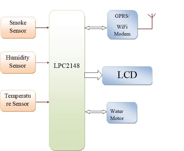
1.5TEMPERATURE SENSOR:
The LM35 series area unit exactness integrated-circuit temperature sensors, whose output voltage is linearly proportional to the Anders Celsius (Centigrade) temperature. The LM35 so has a plus over linear temperature sensors mark in ° Kelvin, because the user isn’t needed to figure an outsized constant voltage from its output to get convenient Centigrade scaling. The LM35 doesn’t need any external standardisation or trimming to produce typical accuracies of ±1⁄4°C at temperature and ±3⁄4°C over a full −55 to +150°C temperature vary.
Low value is assured by trimming and standardisation at the icon resist layer. The LM35’s low output electrical resistance, linear output, and precise inherent standardisation create interfacing to readout or managementelectronic equipment particularly simple. It will be used with single power provide, or with provide of 2 polarities. because it attracts solely sixty μA from its provide, it’s terribly low self-heating, but zero.1°C in still air. The LM35 is rated to control over a −55° to +150°C temperature vary.
Features
• Calibrated directly in ° Anders Celsius (Centigrade)
• Linear + ten.0 mV/°C multiplier factor
• 0.5°C accuracy guarantee ready (at +25°C)
• Rated for full −55° to +150°C vary
• Suitable for remote applications
• Low value owing to wafer-level trimming
• Operates from four to thirty volts
• Less than sixty μA current drain
• Low self-heating, 0.08°C in still air
• Nonlinearity solely ±1⁄4°C typical
1.6SMOKE detector :
A gas detector could be a device that detects the presence of varied gases inside a vicinity, typically as a part ofa security system. thusrt|this kind} of apparatus is employed to discover a gas leak and interface with a bearing system so a method will be mechanically pack up. A gas detector also can sound associate alarm to operators within the space wherever the leak is happening, giving them the chance to depart the world. this sort of device is very important as there area unit several gases which will be harmful to organic life, like humans or animals.
Gas discoverors will be accustomed detect flamable, ignitible and cytotoxic gases, and atomic number 8 depletion. this sort of device is employed wide in trade and may be found in several locations like on oil rigs, to observe manufacture processes and rising technologies like electrical phenomenon. they will even be utilized in firefighting.
Types
Gas detectors will be classified in step with the operation mechanism (semiconductors, oxidation, catalytic, infrared, etc.). Gas detectors are available 2 main types: moveable devices and glued gas detectors.
Portable detectors area unit accustomed monitor the atmosphere around personnel and area unit worn on covering or on a belt/harness. These gas detectors area unit typically battery operated. They transmit warnings via a series of sounding and visual signals like alarms and flashing lights, once dangerous levels of gas vapors area unit detected. As detectors live a gas concentration, the detector responds to a standardisation gas, that is the point of reference or scale. As a sensor’s detection exceeds a predetermined alarm level, the alarm or signal are activated. As units, gas detectors area unit created as moveable or stationary devices. Originally, discoverors were created to detect one gas, however trendy units could discover many cytotoxic or flamable gases, or maybe a mixture of each sorts.
Fixed sort gas detectors is also used for detection of 1 or additional gas sorts. mounted sort detectors area unitusually mounted close to the method space of a plant or room. Generally, they’re put in on mounted sort low-carbon steel structures, and a cable connects the detectors to a SCADA system for continuous observance. A tripping interlock will be activated for associate emergency state of affairs.
Newer gas analyzers will cut the element signals during a difficult aroma to spot many sorts of gases.
Calibration
All gas detectors should be mark on a schedule. Of the 2 sorts of gas detectors, portables should be markadditional oft owing to the regular changes in surroundings they expertise. A typical standardisation schedule for a hard and fast system is also quarterly, bi-annually or maybe annually with a number of the additional sturdy units. A typical standardisation schedule for a conveyable gas detector could be a daily bump take a look atamong a monthly standardisation. virtually each moveable gas detector out there incorporates a specific standardisation gas demand that is out there from the manufacturer you bought your monitor from.
Oxygen concentration
Oxygen deficiency gas monitors ar used for worker and hands safety. refrigerant substances like cryogen (LN2), liquid argonon (He), and liquid element (Ar) ar inert and might displace O (O2) during a confined area if a leak is gift. A speedy decrease of O will offer a awfully dangerous setting for workers, World Health Organizationmight not notice this drawback before they suddenly lose consciousness. With this in mind, AN O gas monitor is very important to possess once cryogeny ar gift. Laboratories, MRI rooms, pharmaceutical, semiconductor, and refrigerant suppliers ar typical users of O monitors.
Oxygen fraction during a respiratory gas is measured by electro-galvanic electric cell sensors. they’ll be used complete, as an example to see the proportion of O during a nitrox mixture employed in skin diving, or as a part of electrical circuit that maintains a relentless partial pressure of O during a rebreather.
Hydrocarbons and VOCs
Detection of hydrocarbons are often supported the blending properties of vaporized hydrocarbons – or alternative volatile organic compounds (VOCs) – and also the sensing material incorporated within the detector. The property and sensitivity depends on the molecular structure of the VOC and also the concentration; but it’s troublesome to style a selective detector for one VOC. several VOC sensors find employing a fuel-cell technique.
VOCs within the setting or bound atmospheres are often detected supported completely different principles and interactions between the organic compounds and also the detector parts. There ar electronic devices which willfind ppm concentrations despite not being significantly selective. Others will predict with cheap accuracy the molecular structure of the volatile organic compounds within the setting or fenced atmospheres and will be used as correct monitors of the Chemical Fingerprint and additional as health watching devices.
Solid-phase microextraction(SPME)techniques ar accustomed collect VOCs at low concentrations for analysis.
Considerations for detection of organic compound gases /risk management
• Methane is lighter than air (possibility of accumulation beneath roofs)
• Ethane is slightly heavier than air (possibility of pooling at ground levels / pits)
• Propane is heavier than air (possibility of pooling at ground levels / pits)
• Butane is heavier than air (possibility of pooling at ground levels / pits)
1.7 wetness Sensor:
1.7.1 what’s Humidity:
Humidity is that the presence of water in air. the quantity of vapour in air will have an effect on human comfort still as several producing processes in industries. The presence of vapour additionally influences numerous physical, chemical, and biological processes.
Fig. 1.7.1.Humidity detector
Humidity measure in industries is important as a result of it’s going to have an effect on the business price of the merchandise and also the health and safety of the personnel. Hence, wetness sensing is extremely necessary, particularly within the management systems for industrial processes and human comfort.
Controlling or observance wetness is of preponderant importance in several industrial & domestic applications. In semiconductor business, wetness or wet levels must be properly controlled & monitored throughout wafer process. In medical applications, wetness management is needed for metabolic process instrumentality, sterilizers, incubators, pharmaceutical process, and biological product. wetness management is additionally necessary in chemical gas purification, dryers, ovens, film desiccation, paper and textile production, and food process. In agriculture, measure of wetness is very important for plantation protection (dew prevention), soil wetobservance, etc. For domestic applications, wetness management is needed for living setting in buildings, preparation management for microwave ovens, etc. all told such applications and plenty of others, wetness sensors area unit used to produce a sign of the wet levels within the setting.
1.7.2 Relevant wet Terms
To mention wet levels, type of terminologies area unit used. The study of water vapor concentration in air as a perform of temperature and pressure falls underneath the realm of psychometrika. psychometrika deals with the thermodynamical properties of dampish gases whereas the term “humidity’ merely refers to the presence of water vapor in air or alternative carrier gas.
Most commonly used units for wetness measure area unit ratio (RH), Dew/Frost purpose (D/F PT) and elements Per Million (PPM). RH could be a perform of temperature, and so it’s a relative measure. Dew/Frost purpose could be a perform of the pressure of the gas however is freelance of temperature and is so outlined as absolute wetness measure. PPM is additionally associate absolute measure.
Dew points and frost points area unit typically used once the waterlessness of the gas is very important. saturation point is additionally used as associate indicator of vapour in warm temperature processes, like industrial drying.
Mixing ratios, volume p.c, associated specific wetness area unit typically used once vapour is either an impurity or an outlined element of a method gas mixture employed in producing.
Correlation among RH, Dew/Frost purpose and PPMv is shown below:
Fig.1.7.2 Relevant wet Terms
1.7.3 Humidity Sensing – Classification & Principles
According to the measure units, wetness sensors area unit divided into 2 types: {relative wetness|ratio} (RH) sensors and absolute humidity (moisture) sensors. Most wetness sensors area unit ratio sensors and use completely different sensing principles.
Sensing Principle
Humidity measure is done mistreatment dry and wet bulb hygrometers, saturation point hygrometers, and electronic hygrometers. There has been a surge within the demand of electronic hygrometers, typically known aswetness sensors.
Electronic sort hygrometers or wetness sensors is generally divided into 2 categories: one employs electrical phenomenon sensing principle, whereas alternative use resistive effects
1.7.3 Sensors supported electrical phenomenon effect:
Humidity sensors looking forward to this principle consists of a absorptive insulator material sandwiched between a combine of electrodes forming alittle condenser. Most electrical phenomenon sensors use a plastic or chemical compound because the insulator material, with a typical insulator constant starting from a pair of to fifteen. In absence of wet, the insulator constant of the absorptive insulator material and also the detector pure mathematics confirm the worth of capacitance.
At traditional temperature, the insulator constant of vapour encompasses a price of regarding eighty, a worth a lot of larger than the constant of the detector insulator material. Therefore, absorption of vapour by the detectorends up in a rise in detector capacitance.
At equilibrium conditions, the quantity of wet gift in a very absorptive material depends on each the close temperature and also the close vapour pressure. this can be true additionally for the absorptive insulator material used on the detector.
By definition, ratio could be a perform of each the close temperature and vapour pressure. so there’s a relationship between ratio, the quantity of wet gift within the detector, and detector capacitance. This relationship governs the operation of a electrical phenomenon wetness instrument.
Basic structure of electrical phenomenon sort wetness detector is shown below:
Fig.1.7.3.a.Capactive sort wetness detector
On aluminum oxide substrate, lower conductor is made mistreatment gold, atomic number 78 or alternative material. A chemical compound layer like polyvinyl resin is deposited on the conductor. This layers senses wetness. On prime of this chemical compound film, gold layer is deposited that acts as prime conductor. the highest conductor additionally permits water vapor to undergo it, into the sensing layer. The vapors enter or leave the absorptive sensing layer till the vapour content is in equilibrium with the close air or gas. so electrical phenomenon sort detector is largely a condenser with wetness sensitive chemical compound film because theinsulator.
Sensors supported Resistive effect:
Resistive sort wetness sensing {element|device}s acquire modifications within the resistance price of the sensor element in response to the change within the wetness. Basic structure of resistive sort wetness detector from TDK is shown below
Fig.1.7.3.b.Resistive sort wetness detector
Thick film conductor of precious metals like gold, atomic number 44 compound is written associated calcinated within the form of the comb to create an conductor. Then a chemical compound film is applied on the electrode; the film acts as a wetness sensing film thanks to the existence of movable ions. modification in ohmic resistancehappens thanks to the modification within the variety of movable ions.
1.8Relay:
It is AN device that functions one thing sort of a wired remote switch. rather than having the switch you push/flip/whatever do the work of activity power to no matter you wished it to, you have got it management a relay that then will the $64000 on/off change work. That’s it. It’s very not terribly sophisticated, now is it?
A mechanical relay will this through the employment of AN magnet – a magnet that’s solely “on” once there is power running through it – that pulls a group of spring loaded contacts to form or break the association and deliver the goods the on-off impact. this is often referred to as the “coil” or trigger wire – the opposite wire setting out of the coil is connected to ground. Whenever you apply power to the opposite coil wire (the trigger), the relay is on. As before long as power to the current trigger is turned off, the relay turns off. There also are “solid state” relays that deliver the goods constant impact through transistors. Either one functions constant means, the solid state stuff simply has no moving elements to wear out, however they have an inclination to be costlier and not as promptlyaccessible since the regular mechanical ones square measure inexpensively and promptly accessible as terriblyprime quality, sturdy units.
1.8.1 Why is that this useful?
For one massive reason – some devices use lots of power which suggests that massive wires and significant duty contacts within all of the switches and connectors square measure required. And you wish to use as very little wire (in length/distance) as potential. It’s costlier and heavier that smaller low-power wires and it’s tougher to figure with. If the wire develops a brief, it is a abundant larger drawback – and therefore the longer the wire concerned, the additional probabilities you have got for one thing to travel wrong.
A relay alleviates this by employing a single comparatively little and low power wire to regulate the on-off of electrical flow. You mount the relay close to the device it controls, and run an easy massive power wire to the relay. Then you run atiny low wire back to the switch. The switch you flip simply provides power to the relay coil and functions as a trigger -the high power association to your device.
1.8.2 Relay ratings and configurations:
Relays square measure usually mentioned in terms of many things.
• what quantity power the high power aspect will handle in Amps
• The voltage and power sort (AC or DC) the coil must operate
• the amount and kind of contacts the relay has
The first issue, the facility rating, is incredibly straightforward – a relay is rated for its capability to handle power. that is what it’s for, and that is what you hear most frequently. it’ll be delineated as a 20A, 30A, or no matter relay. This should be as massive as or larger than the utmost rating of the issue you wish to regulate with the relay. it’ll be rated at some voltage still, therefore make certain it all matches.
The second issue, the coil voltage and kind, is usually omitted once operating during a better-known setting. All automotive relays use a 12V DC coil, therefore this data is tacit if the relay is meant to be used during aautomobile. to be used in alternative environments (home, industrial, etc.) there’ll be a rating on what the relay coil expects. simply match this to what the trigger wire can have in it. Note that the coil doesn’t have to be compelled to work on constant voltage because the voltage being sent over the high power contacts. there’s no got to send high voltage to {the little|the tiny|the little} switch – the complete purpose is to use small wires and switches to regulate the relay, after all. The common case here may be a push in your house. the particular pushbutton outside is usually being fed 24V AC and it hooks up to a relay within the push chime unit to form the chime happen. The chime can typically work on 120V AC (normal unit electricity), therefore the relay controls this.
The third issue, the amount and kind of contacts, is employed {to management|to regulate|to manage} numerous things promptly and control them by turning them on or by turning them off. this is often delineated within the same means the other switch is delineated – by range|the amount|the quantity} of poles and therefore the number of throws. Most automotive square measure terribly straightforward and of the SPST or SPDT selection – scan below to be told what meaning.
The number of contacts (or poles), is that the variety of things that the relay will management promptly. The relay is simply AN electromagnetically controlled switch, and you’ll be able to have constant magnet flip variety of switches in unison constant means you may mount a bar across variety of various switch levers to force them to be switched in unison. a decent example of this is often the circuit breakers in our homes. a number of them are 2 breakers tied along with a bar in order that they switch along to form a 2 pole switch out of 2 single pole switches. With a relay, this is often terribly helpful for creating one switch management 2 various things – like turning on the parking lights and therefore the dash lights in your automobile with one switch.
The range of throws is that the number of distinct contacts you’ll send power to – the amount of places you’ll “throw” the switch to. Typically, you have got one input and one or a lot of outputs. If you’ll connect the output to 1factor, as in a very easy electrical switch, you have got one throw. If you have got 2 outputs, like in a very power window switch wherever you have got up and down, you have got 2 throws. If it had been a lot of sort of a dial switch wherever you may choose from 3 or a lot of things, just like the fan speed management switch, then you’d have 3 or a lot of throws.
This is range of poles and range of throws is selected with a straightforward abbreviation like “SPST”. This stands for Single Pole, Single Throw. Another common one is “DPDT”, that is for Double Pole, Double Throw. on the far side that they’re typically selected with numbers, like “3PDT” (Three Pole, Double Throw) or “SP4T” (Single Pole, Four Throw”. By staring at this data, will|you’ll|you’ll be able to} tell however the relay can switch things, and decide if it’s right for your wants. As noted higher than, most automotive area unit terribly easy and of the SPST or SPDT selection – they will management one factor and switch it on or off, or apply power to 1 of 2 various things.
Lastly, the contacts within the switch or relay area unit delineated as “normally open” (NO) or “normally closed” (NC). This merely describes what the “at rest” state is. For a relay, which means if no power is applied to the coil/trigger wire. within the typical case wherever you would like to show one thing on, you employ the “normally open” set of contacts so after you apply power to the relay, the contacts shut, and power is distributed to the specified device. this is often used for things like turning on your fog lights or things like that. within the case of needing to flip one thing off, you employ the “normally closed” set of contacts so after you apply power to the relay, the contacts open and also the power is not any longer sent to the specified device. this is often used for things like AN emergency stop switch or alternative bizarre “control” cases. One example is in sure multiple relay electrical fuel pump setups on fuel injected vehicles to regulate once the pump is on ANd to make sure it turns off just in case} of the engine stall – this is often accustomed scale back the danger of fireside (due to the pump still pumping fuel) in case of an accident and a busted piping.
1.8.3 Typical Automotive Relay
This diagram hows a typical Hieronymus Bosch relay utilized in the automotive world. it’s the nearest factor to a universal relay commonplace within the automotive world, therefore you may see this kind of diagram and/or contact listing system typically if you’re employed on cars enough. {this is|this is typically|this can be} very truewithin the hot-rod or “aftermarket” area unitna wherever these vogue relays are often accustomed deliver the goods custom or “trick” effects on a vehicle like something that opens or closes with a motor, or the “no door handles” look wherever the door is unsecured electrically rather than automatically.
This relay may be a SPDT relay with one NO contact (terminal 87) and one North Carolina contact (terminal 87a). These relays typically have atiny low schematic drawing wrought into the highest of the relay and every one of the contacts area unit clearly labelled on the relay therefore you’ll trace the wiring with ease. They conjointly use a customary size and configuration for his or her plug-in terminals so you’ll get a customary wrought plastic base with the right wiring hookups in it. This enabled you to disconnect all of the connections all directly for easycoupling – like if you would like to check or replace the relay itself.
Fig.1.8.3.SPDT RELAY
Notice within the higher than diagram that a relay uses AN magnet. this is often a tool consisting of a coil of wire wrapped around AN iron core. once electricity is applied to the coil of wire it becomes magnetic, thence the term magnet. The A B ANd C terminals area unit an SPDT switch controlled by the magnet. once electricity is applied to V1 and V2, the magnet acts upon the SPDT switch so the B and C terminals area unit connected. once the electricity is disconnected, then the A and C terminals area unit connected. it’s vital to notice that the magnet is magnetically joined to the switch however the 2 aren’t joined electrically.
there’s another variety of relay known as a magnet that primarily works on identical principle. The magnetmagnet consists of wire wrapped around a tube containing AN iron cylinder known as a “plunger”. once electricity is provided to the wire coil, the “plunger” moves through the tube and activates a switch.
At now you may be inquisitive concerning the aim of all this. Why switch AN magnet with great care it willmanagement another switch? Why not simply use one regular switch? One vital application is illustrated within the diagram below.
FIG.1.8.3.b.Automobile starter circuit
NOTE: the image indicates a ground affiliation. Since an excellent share of AN automobile consists of metal, exploitation the auto itself joined “side” of a circuit saves an incredible quantity of wire.
When the key is turned all the thanks to the “start” position, it permits electricity to flow to the starter magnet (relay) that then connects the battery to the starter. could not we have a tendency to simply eliminate it and connect the ignition wires to the + battery terminal and therefore the different wire to the starter? The vital purpose here is that the magnet is employing a quantity|bit|touch} of current to manage an outsized amount of current to the starter motor. (Remember that the magnet and therefore the switch aren’t connected electrically). have you ever detectedthat each one of the wires (except the ignition wires) area unit advisedly drawn with thick lines? the explanation being that some circuits (such because the starter) during a automobile need an amazing quantity of current. (If you scrutinize Associate in Nursing automobile’s battery cables, you may notice they’re quite thick.) Connecting the ignition wires to the battery so to the starter would cause these skinny wires to conduct way more current than they were designed for. These wires would become very popular and therefore the insulation would begin to smoke. (The same would hold true for the ignition switch). when beginning the automobile for simply a number of times, the wires and therefore the switch would be in unhealthy form.
we have a tendency to do have a second alternative. we have a tendency to may use thick battery cables for the ignition wires and use an important duty electric switch. this is not terribly sensible either. does one supposeit’d be simple to squeeze cables into the steering column and to squeeze during a serious duty electric switch too? so, the utilization of a magnet is that the most sensible resolution.
For future circuits, we have a tendency to suggest employing a nine V battery, a nine V electronic siren (or buzzer) and a nine V SPDT relay.
Another sensible use of relays is for shift one circuit ‘on’ once another circuit has been switched ‘off’ or broken. What potential application needs such Associate in Nursing odd shift arrangement? however a few stealer alarm?
Fig.1.8.3.c. alarm circuit
bearing on the on top of diagram, let’s trace the electrical flow. Since the alarm loop wire connects points ‘V2’ to ‘C’, it will simply be seen that electricity flows from the negative battery terminal, goes to V1 then V2, then (because the alarm loop is unbroken) it goes to C and eventually to the positive battery terminal. during this circuit, current is flowing through the magnet, inflicting the SPDT switch to create contact with terminal B. due to this, the siren doesn’t sound as a result of there’s NO current getting to purpose A.
currently let’s suppose that the alarm loop is broken. The wire doesn’t essentially got to be move trigger the alarm. maybe one or additional magnetic switches might be wired asynchronous within the alarm loop and once one magnet moves, it causes the switch contact to interrupt so the alarm can sound. The electricity is currently flowing across points C and A to the siren and NOT the magnet.
Alarm Circuit one will suffer from one serious flaw. are you able to see what it is? If the alarm loop is reconnected, the siren shuts off. this can be NOT counseled for any serious warning device. After all, if a door with a magnetic switch is forced open, all a stealer would got to do is shut the door. The siren then explodes ! there’s an improvedthanks to wire Associate in Nursing alarm.
Fig.1.8.3.d.alarm circuit
Alarm Circuit two appearance terribly like Circuit one, the sole distinction being that one aspect of the alarm loop currently goes to purpose B rather than purpose C. What happens once current is applied to the current circuit? The siren sounds off forthwith and stays on unendingly. Hmmm, that certain sounds like Associate in Nursing annoying alarm circuit.
By employing a scrap of wire, quickly connect purpose B to purpose C. The alarm shuts off forthwith. If you break the alarm loop, the siren sounds all over again. If the alarm loop is reconnected then siren still blasts away.
Temporarily connecting points B and C causes current to flow through the magnet, that attracts the switch to purpose B. As long because the alarm loop remains unbroken the alarm remains silent. Break the alarm loop, the alarm sounds. not like Circuit one, reconnecting the alarm loop not causes current to flow through the magnet. the sole thanks to activate the magnet is by connecting points B and C.
within the ‘real world’, the relay, the facility offer (battery) and therefore the siren ought to be inaccessible to everybody except those licensed to ‘arm’ and ‘disarm’ it. we will simply see that the alarm might be ‘sabotaged’ during a range of how if unauthorized persons had access thereto. Incidentally, this kind of circuit is named a supervised warning device.
If the alarm loop were to be broken, you’d ne’er be ready to arm it. Therefore, during a world application, if the alarm can’t be armed, you’d understand one thing was wrong (a door may be open, a wire may be broken, etc.). Also, in world applications, Associate in Nursing alarm would be way more complicated than the one shown here. The equipping method would most likely be finished a key switch. The alarm may additionally have flashing lights, Associate in Nursing automatic phone dialer to the police so on. The circuits shown area unit for demonstration and academic functions solely and NOT meant to be employed in place of skilled alarm systems.
a new circuit ought to be shown as a result of in reality, identical power offer most likely wouldn’t operate the alarm loop similarly because the warning circuit. The diagram for such an appointment is shown below in Alarm Circuit three.
haven’t any text to check? haven’t any text to check? Click “Select Samples”. As is that the case with several mechanical devices being replaced by their electronic equivalents, relays ar being “phased out” by Solid State Relays (SSR’s). Mechanical relays do have their disadvantages when put next to AN SSR:
1) switch is far slower
2) the contacts wear out
3) they create noise after they switch
4) their magnetic fields will cause issues for close
components
Presently, their one advantage is their ability to change high voltage and high current circuits. (The automobile starter magnet for example). little question with time, even this may be surpassed by the SSR. a minimum of mechanical relays will simply demonstrate the principles of electrical/electronic switch.
Step-down transformers
Fig.1.8.3.e.Step down transformers
Step down transformers ar designed to scale back electrical voltage. Their primary voltage is larger than their secondary voltage. this type of electrical device “steps down” the voltage applied thereto. as an example, a step down electrical device is required to use a 110v product during a country with a 220v provide.
Step down transformers convert electrical voltage from one level or section configuration sometimes right down to a lower level. they will embrace options for electrical isolation, power distribution, and management and instrumentation applications. Step down transformers generally consider the principle of magnetic induction between coils to convert voltage and/or current levels.
Step down transformers ar made up of 2 or a lot of coils of insulated wire wound around a core made from iron. once voltage is applied to at least one coil (frequently referred to as the first or input) it magnetizes the iron core, that induces a voltage within the different coil, (frequently referred to as the secondary or output). The turns quantitative relation of the 2 sets of windings determines the quantity of voltage transformation.
An example of this could be: one hundred activates the first and fifty activates the secondary, a quantitative relation of two to one.
Step down transformers are often thought of nothing quite a voltage quantitative relation device. With step down transformers the voltage quantitative relation between primary and secondary can closed.
CHAPTER 2
MICROCONTROLLER
2.1 Introduction:
A complex instruction set pc, unremarkably referred to as CISC, is in complete distinction to the reduced instruction set pc, unremarkably referred to as computer architecture. each represent 2 entirely completely different philosophies in trendy pc design. Some microcontrollers supports the {risc|reduced instruction set computing|reduced instruction set computer|RISC|computer design|architecture} design some microcontrollers supports the CISC architecture.
The example of the {risc|reduced instruction set computing|reduced instruction set computer|RISC|computer design|architecture} design is 8085 microcontroller and ARM microcontrollers supports the computer architecture architecture.
2.2 Differences between the computer architecture and CISC Architectures:
2.2.1 What is CISC?
In 1964 IBM free the IBM 360 to abundant acclaim. it’s considered the primary trendy processor system and adopted the conception of micro-coded management. Micro-coded management accommodated the employment of complicated instruction sets that may be a important conception at intervals CISC design. A CISC central process unit acknowledges a colossal quantity of directions that denote extremely complicated task. The CISC based mostly design tends to throw the sink at the matter, things that area unit common to the design include:
It allowed for a way simpler compiler as extraordinarily complicated tasks were enforced in micro-coding
Instruction sets for loops
Instruction sets for procedure calls
Complex addressing modes
Small program sizes, complicated routines completed by hardware
2.2.2 What is RISC?
A computer architecture (Reduced Instruction Set Computer) based mostly system contains a way a lot ofreduced instruction set, permitting the coder to interrupt their application into abundant smaller steps, doing less, and simplifying their solutions. it had been developed in response to the CISC approach and maintained that complicated addressing took several instruction cycles to perform and would be far better expedited by sequences of less complicated directions at a way higher frequency. computer architecture stressed the directions that were used most frequently and more optimized them for the quickest doable execution. {risc|reduced instruction set computing|reduced instruction set computer|RISC|computer design|architecture} architecture would have the subsequent common characteristics:
• Uniform instruction formats
• Identical and lots of a lot of general purpose registers
• Extremely easy addressing modes
• Very few knowledge sorts
• A reduced instruction set
• Simplified design
• Larger program sizes, complicated routines area unit completed by the compiler
• Less expensive to style, test, and manufacture
• Faster process
RISC maintains some, easy pipelined directions with fastened length and generally one instruction/cycle. They support solely register-to-register operations and some easy addressing modes (usually register addressing).
2.2.3 Uses of CISC:
Some common CISC based mostly processors enclosed the System/360, VAX, PDP-11, Motorola 68000 family, and Intel x86 design based mostly processors. The CISC based mostly architecture’s crowning glory must are the Intel x86 lines in my opinion. The x86 generation defines the primary few processor generations that were backward compatible with the first Intel 8086 and has revolutionized personal computing as we all know it. The x86 design is currently supported by a colossal quantity of code and operative platforms like the subsequent systems, from MS-DOS, Windows, BSD, Linux, Solaris and recently a lot of recently mack OS-X. Through these systems, CiSC will be seen throughout all industries from fashion to finance and from engineering to attention. To more push the CISC design, Intel sharply marketed the Pentium 486 processors, this single act allowed individuals to possess CISC based mostly processors at a fraction of their development value and adjusted the layout of the computer architecture versus CISC discussion.
2.2.4 Uses of RISC:
The {risc|reduced instruction set computing|reduced instruction set computer|RISC|computer design|architecture} based mostly architecture has become a lot of distinguished within the industry but it’s solely in recent times that this has become evident. The computer architecture chip is quicker than its CISC counterpart because it is meant and designed a lot of economically, and preponderantly retains those directions which will be dead in one machine cycle or less. The computer architecture chip’s influence will be seen latterly at intervals the Apple IPod, its ARM design dominates the marketplace for high preciseness, lower power, low value mobile embedded devices and is employed in high category diversion consoles like the Nintento Wii, Sony Play station three and throughout several different consoles like the XBOX 360 (Controller).
The {risc|reduced instruction set computing|reduced instruction set computer|RISC|computer design|architecture} based mostly design has little or no impact on the desktop computer market wherever Intel’s x86 architecture remains the dominant processor, but it’s creating massive inroads into the high-end server market, it ought to even be noted that in 2008 a {risc|reduced instruction set computing|reduced instruction set computer|RISC|computer design|architecture} based mostly architecture, Power Architecture-based Cell processors, within the IBM’s cuckoois that the darling recognized mainframe computer within the world. It ought to still be noted that the overwhelming majority of different supercomputers area unit victimisation the x86 CISC design too.
2.3 Features of Arm design
2.3.1 Key features:
16-bit/32-bit ARM7TDMI-S microcontroller in an exceedingly little LQFP64 package
8 computer memory unit to forty computer memory unit of on-chip static RAM and thirty two computer memory unit to 512 computer memory unit of on-chip flash memory; 128-bit wide interface/accelerator allows high-speed sixty rate operation
In-System Programming/In-Application Programming (ISP/IAP) via on-chip boot loader code, single flash sector or full chip erase in four hundred ms and programming of 256 B in one ms.
Embedded ICE RT and Embedded Trace interfaces provide period of time debugging with the on-chip Real Monitor code and high-speed tracing of process
USB 2.0 Full-speed compliant device controller with a pair of computer memory unit of termination RAM
In addition, the LPC2146/48 provides eight computer memory unit of on-chip RAM accessible to USB by DMA
One or 2 (LPC2141/42 vs, LPC2144/46/48) 10-bit ADCs offer a complete of 6/14 analog inputs, with conversion times as low as a pair of.44 ms per channel Single 10-bit DAC provides variable analog output (LPC2142/44/46/48 only)
Two 32-bit timers/external event counters (with four capture and 4 compare
channels each), PWM unit (six outputs) and watchdog.
Low power period of time Clock (RTC) with freelance power and thirty two rate clock input
Multiple serial interfaces as well as 2 UARTs (16C550), 2 quick I2C-bus (400 kbit/s),
SPI and SSP with buffering and variable knowledge length capabilities
Vectored Interrupt Controller (VIC) with configurable priorities and vector addresses
Up to forty five of five V tolerant quick general purpose I/O pins in an exceedingly little LQFP64 package
Up to twenty one external interrupt pins out there
60 rate most CPU clock out there from programmable on-chip PLL with subsiding time of a hundred msPower saving modes include Idle and Power-down
Individual enable/disable of peripheral functions in addition as peripheral clock scaling for added power improvement
Processor wake-up from Power-down mode via external interrupt or physique
Single power offer chip with POR and physique circuits:
CPU in operation voltage vary of three.0 V to 3.6 V (3.3 V ± ten %) with five V tolerant I/O pads.
2.1 Criteria For selecting A Microcontroller
1. the primary and foremost criterion for selecting a microcontroller is that it should meet task at hands expeditiously and price effectively. In associate degreealyzing the requirements of a microcontroller primarily based project we tend to should initial see whether or not it’s an 8-bit, 16-bit or 32-bit microcontroller and the way best it will handle the computing desires of the task most effectively. the opposite issues during this class are:
(a) Speed: the very best speed that the microcontroller supports
(b) Packaging: Is it 40-pin DIP or QPF or another packaging format?
This is vital in terms of house and prototyping the tip product.
(c) Power Consumption: this is often particularly crucial for powered
Products.
(d) the number of RAM and computer storage on chip
(e) the amount of I/O pins and timers on the chip.
(f)Cost per unit: this is often vital in terms of ultimate product within which used.
2. The second criteria in selecting a microcontroller square measure however straightforward it’s to develop merchandise around it. Key issues embody the provision of associate degree program, debugger, a code economical ‘C’ language compiler, emulator, technical support and each in house and outdoors experience. In several cases third party merchandiser support for chip is needed.
3. The third criteria in selecting a microcontroller is it pronto on the market in required quantities each currently and in future. for a few designers this is often even additional vital than initial 2 criteria’s. Currently, of leading 8–bit microcontrollers, the 89C51 family has the most important range of diversified (multiple source) suppliers. By suppliers meant a producer besides the creator of microcontroller within the case of the 89C51, that was originated by Intel, many firms also are presently manufacturing the 89C51. Viz: INTEL, ATMEL, These firms embody PHILIPS, SIEMENS, and DALLAS-SEMICONDUCTOR. It ought to be noted that Motorola, Zilog and semiconductor Technologies have all dedicated huge resource on guarantee wide and timely accessibility of their product since their product is stable, mature and single sourced. In recent years they even have begun to sell the ASIC library cell of the microcontroller.
2.2 General description of LPC 2148:
The LPC2148 microcontrollers is predicated on a 32-bit ARM7TDMI-S C.P.U. with period emulation and embedded trace support, that mix microcontrollers with embedded high-speed nonvolatile storage starting from thirty twokilobyte to 512 kilobyte. A 128-bit wide memory interface and distinctive accelerator design change 32-bit code execution at the utmost clock rate. For crucial code size applications, the choice 16-bit Thumb mode reduces code by over half-hour with marginal performance penalty.
because of their little size and low power consumption, LPC2141/42/44/46/48 square measure ideal for applications wherever shrinking may be a key demand, like access management and location. Serial communications interfaces starting from a USB a pair of.0 Full-speed device, multiple UARTs, SPI, SSP to I2C-bus and on-chip SRAM of eight kilobyte up to forty kilobyte, build these devices all right fitted to communication gateways and protocol converters, soft modems, voice recognition and low finish imaging, providing each giant buffer size and high process power. varied 32-bit timers, single or twin 10-bit ADCs, 10-bit DAC, PWM channels and forty five quick GPIO lines with up to 9 edge or level sensitive external interrupt pins build these microcontrollers appropriate for industrial management and medical systems.
2.3 General summary of in system programming (ISP):
In-System Programming (ISP) may be a method whereby a blank device mounted to a board are often programmed with the end-user code while not the necessity to get rid of the device from the board. Also, a antecedently programmed device are often erased and Re programmed while not removal from the board. so as to perform ISP operations the microcontroller is supercharged up during a special “ISP mode”. ISP mode permits the microcontroller to speak with associate degree external host device through the interface, like a computer or terminal. The microcontroller receives commands and knowledge from the host, erases and reprograms code memory, etc. Once the ISP operations are completed the device is reconfigured so it’ll operate commonly following time it’s either reset or power removed and reapplied. All of the Philips microcontrollers shown in Table one and Table a pair of have a one Kbyte factory-masked computer storage placed within the higher one Kbyte of code memory house from FC00 to FFFF. This one Kbyte computer storage is additionally to the memory blocks shown in Table one and Table a pair of. This computer storage is cited because the “Boot rom”. This Boot computer storage contains a group of directions that permits the microcontroller to perform variety of Flash programming and erasing functions. The Boot computer storage conjointly provides communications through the interface. the employment of the Boot computer storage is vital to the ideas of each ISP and In-Application Programming (IAP). The contents of the boot computer storage square measure provided by Philips and disguised into each device. once the device is reset or power applied, and also the EA/ pin is high or at the VPP voltage, the microcontroller canbegin capital punishment directions from either the user code memory house at address 0000h (“normal mode”) or can execute directions from the Boot computer storage (ISP mode)
2.1 General summary of In Application Programming:
Some applications might have a requirement to be able to erase and program code memory below the management of the applying. as an example, Associate in Nursing application might have a requirement to store activity data or maybe ought to be able to transfer new code parts. This ability to erase and program code memory within the end-user application is “In-Application Programming” (IAP). The Boot memory board routines that perform functions on the nonvolatile storage throughout ISP mode like programming, erasing, and reading, also are offered to end-user programs. so it’s attainable for Associate in Nursing end-user application to perform operations on the nonvolatile storage. a standard entry purpose (FFF0h) to those routines has been provided to change interfacing to the end-users application. Functions area unit performed by putting in place specific registers pro re nata by a particular operation and acting a decision to the common entry purpose. like every alternativepackage decision, when completion of the perform, management can come back to the end-user’s code. The Boot memory board is shadowy with the user code memory within the address vary from FC00h to FFFFh. This shadowing is controlled by the ENBOOT bit (AUXR1.5). When set, accesses to internal code memory during this address vary are going to be from the boot memory board. once cleared, accesses are going to be from the user’s code memory. it’ll be NECESSARY for the end-user’s code to line the ENBOOT bit before line of work the common entry purpose for IAP operations, even for devices with sixteen Kbyte, 32 Kbyte, and sixty four Kbyte of internal code memory. (ISP operation is chosen by bound hardware conditions and management of the ENBOOT bit is automatic once ISP mode is activated).
2.2 Block Diagram:
Fig.2.8.Blockdiagram Of Arm7 Microcontroller
2.3 Pin Configuration:
Fig.2.9. Pin diagram
2.3.1 Functional Description:
subject Overview:
The ARM7TDMI-S could be a general purpose 32-bit chip, that offers high performance and extremely low power consumption. The ARM design relies on Reduced Instruction Set laptop (RISC) principles, and therefore the instruction set and connected decrypt mechanism area unit abundant less complicated than those of small programmed advanced Instruction Set Computers (CISC). This simplicity ends up in a high instruction turnout
And spectacular period interrupt response from atiny low and efficient processor core. Pipeline techniques area unit utilized so all elements of the process and memory systems will operate endlessly. Typically, whereas one instruction is being dead, its successor is being decoded, and a 3rd instruction is being fetched from memory. The ARM7TDMI-S processor additionally employs a novel subject strategy called Thumb, that makes it ideally suited to high-volume applications with memory restrictions, or applications wherever code density is a problem. The key plan behind Thumb is that of a super-reduced instruction set.
basically, the ARM7TDMI-S processor has 2 instruction sets:
• the quality 32-bit ARM set
• A 16-bit Thumb set
The Thumb set’s 16-bit instruction length permits it to approach doubly the density of ordinary ARM code whereasretentive most of the ARM’s performance advantage over a standard 16-bit processor victimisation 16-bit registers. this can be attainable as a result of Thumb code operates on a similar 32-bit register set as ARM code. Thumb code is in a position to supply up to sixty five maximize the code size of ARM, and a hundred and sixtieth of the performance of a similar ARM processor connected to a 16-bit memory system. the actual flash implementation within the LPC2141/42/44/46/48 permits for full speed execution additionally in ARM mode. it’s counseled to program performance essential and short code sections (such as interrupt service routines and DSP algorithms) in ARM mode. The impact on the code size are going to be least however the speed is magnified by half-hour over Thumb mode.
On-Chip Flash Program memory:
The LPC2141/42/44/46/48 incorporate a thirty two kilobyte, 64 kB, 128 kB, 256 kilobyte and 512 kilobytenonvolatile storage system severally. This memory could also be used for each code and knowledge storage. Programming of the nonvolatile storage could also be accomplished in many ways that. it’s going to be programmed In System via the port. the applying program might also erase and/or program the flash whereas the applying is running, permitting a good degree of flexibility for knowledge storage field computer code upgrades, etc. because of the subject answer chosen for Associate in Nursing on-chip boot loader, nonvolatile storageoffered for user’s code on LPC2141/42/44/46/48 is thirty two kilobyte, 64 kB, 128 kB, 256 kilobyte and five hundred kilobyte severally.
The LPC2141/42/44/46/48 nonvolatile storage provides a minimum of one hundred thousand erase/write cycles and twenty years of data-retention.
• On-Chip Static RAM:
On-chip static RAM could also be used for code and/or knowledge storage. The SRAM could also be accessed as 8-bit, 16-bit, and 32-bit. The LPC2141, LPC2142/44 and LPC2146/48 offer eight kilobyte, sixteen kilobyte and thirty two kilobyte of static RAM severally. just in case of LPC2146/48 solely, Associate in Nursing eightkilobyte SRAM block meant to be utilised primarily by the USB can even be used as a general purpose RAM for knowledge storage and code storage and execution
Memory Map:

The LPC2141/42/44/46/48 memory map incorporates distinct regions, as shown:
CHAPTER 3
LIQUID CRYSTAL DISPLAY
LCD

Fig.3.1.a.LCD
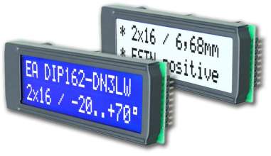
Fig.3.1.b.LCD with data
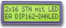
3.1Features
High distinction alphanumeric display Super twist show
Ea Dip162-Dnled: Yellow/Green With diode Backlight
Ea Dip162-Dn3lw And Dip162j-Dn3lw With White diode B/L., Low power
Incl. Hd 44780 Or Compatible Controller
Interface For 4- And 8-Bit knowledge Bus
Power provide +5v Or ±2.7v Or ±3.3v
Operating Temperature 0~+50°C (-Dn3lw, -Dhnled: -20~+70°C)
Led Backlight Y/G soap. 150ma@+25°C
Led Backlight White soap. 45ma@+25°C
Some additional Modules With Same Mechanic And Same Pinout:
-Dotmatrix 1×8, 4×20
-Graphic 122×32
* No Screws Required: Solder On In Pcb solely
* clastic Via 9-Pin Socket Ea B200-9 (2 Pcs. Required)
Liquid crystal show may be a important device in Associate in Nursing embedded system. It offers high flexibility to user as he will show the specified knowledge on that. however thanks to lack of correct approach to alphanumeric display interfacing fails many an times. many folks think about alphanumeric display interfacing a fancy job however per American state alphanumeric display interfacing is extremely straightforward task, you simply got to have a logical approach.
We will comprehend the booster rockets on space vehicle. while not these booster rockets the space vehiclewouldn’t are launched in orbit. equally one must have booster rockets hooked up to know alphanumeric display interfacing! to induce it done right you want to have general plan on a way to approach any given alphanumeric display.
First thing to start with it’s to understand what alphanumeric display driver/controller is employed within thealphanumeric display. alphanumeric display driver is a link between the microcontroller and therefore thealphanumeric display. to understand the alphanumeric display driver one will refer the datasheet of the alphanumeric display for e.g. JHD 162A is name of alphanumeric display having driver HD44780U.You have to interface the alphanumeric display per the motive force specification. to know the rule of alphanumeric display interfacing user should have datasheet of each alphanumeric display and alphanumeric display driver. many folks ignore the datasheets and find yourself in troubles. If you wish to interface alphanumeric display with success you want to have the datasheets.
First thing to search out call at datasheet is that the options like in operation voltage, variety of interface, size of show knowledge RAM, most speed for interface in rate, variety of pixels, bits per component, variety of row and columns. you want to have the pin diagram of alphanumeric display.
Study the sort of communication protocol whether or not it’s parallel or serial interface. Check however Associate in Nursing alphanumeric display discriminates the info bytes and command bytes and that pins on the alphanumeric display square measure used for communication. Study Interface temporal arrangement diagram given within the datasheet.
From datasheet of the alphanumeric display driver, one will resolve the need of hardware reset at the startup and what’s the time of reset pulse, and whether or not it’s active low and that pins of the alphanumeric display square measure to be toggled.
In alphanumeric display interfacing, the format of a sequence is that the major task. within the alphanumeric display format one have to be compelled to send the command bytes to the alphanumeric display. Here one will set completely different modes just like the show mode, interface mode, address counter increment direction, set distinction of alphanumeric display, horizontal or vertical addressing mode, color format. This sequence is given in various to alphanumeric display driver datasheet. finding out the operate set of alphanumeric display lets one to understand the definition of command bytes. It varies from one alphanumeric display to a different. If you’reready to initialize the alphanumeric display properly majority of your job is finished.
Next step when format is to send {the knowledge|the info|the information} bytes to the specified show data RAM memory location. first set the address location victimization address set command computer memory unit and so send knowledge bytes victimization the DDRAM write command. to deal with specific location in show knowledge RAM one should have the data of however the address counter is incremented
CHAPTER 4
EMBEDDED SYSTEM
4 What Is AN Embedded System?
As the name signifies, AN embedded system is ‘embedded’ or engineered into one thing else, that could be a non-computing device, take into account a automobile, TV, or toy. in contrast to a computer, AN embedded pc in an exceedingly} non-computing device can have a very specific perform, say management a automobile, or show websites on a TV screen. So, it needn’t have all the practicality and thus all the elements that a computer has. Similarly, the software package and therefore the applications needn’t perform all the tasks that ar expected to counterpart from the computer sphere.
In short, we are able to outline AN embedded system as a information processing system, engineered into a tool that’s not a pc, and meant for doing specific computing tasks. These computing tasks might vary from getting or transferring information regarding the work done by the mother device to displaying data or dominant the mother device. Embedded systems might therefore change United States of America to create intelligent machines.
Embedded systems don’t seem to be a brand new and exotic topic that’s still confined to analysis theses. There ar several live samples of embedded systems in our surroundings. MP3 players (computing capability engineered into a music system), PDAs (computing in what basically is AN organizer), car-control systems, and intelligent toys ar however some samples of such systems already in situ.
A typical embedded system consists of hardware (typically VLSI or terribly large-scale integrated circuits) specifically engineered for the aim, AN embedded software package, and therefore the specific application or applicatiospecification is taken into account to be AN extension of the ISA bus specification. Since the computer /104 commonplace has been extended to PC/104-plus to incorporate the PCI bus. So, nowadays you’ve got PC-based embedded systems that have the ISA bus, the PCI bus, or both.
Unlike with regular PCs, within the world of the embedded computer, 386s, 486s and Pentiums ar still ok. Besides these, there ar variety of CPUs meant specifically for embedded applications just like the StrongArm and therefore the unit.
With embedded PCs you’ll be able to even transcend the single-function definition of AN embedded system, and will build a whole computer into another machine; a computer within a white goods, or a computer within a automobile, for example.
3.1 Hardware for Embedded Devices
Universal small system could be a general hardware which will be programmed and accustomed develop applications for various embedded devices
Many fashionable appliances like MP3 players, refrigerators UMS and watches use embedded systems. However, a typical obstacle for developers has been the requirement to develop totally different sets of hardware and package, for various devices. AN intelligent washer uses a hardware chip totally different from that utilized by AN ‘intelligent’ watch. additionally, the package running on the hardware chip is totally different. This usually leads to accrued prices and time taken for development.
The Universal small System (UMS) from Cradle Technologies could be a resolution for this drawback. UMS could be a general chip engineered around an easy instruction set. It may be accustomed develop applications for embedded devices as a result of all the practicality needed for a selected device may be modelled within the package.
Ums Hardware: The Input/Output unit of UMS is programmable. you’ll program it to support process unit dependant information transfers, or do a DMA information transfer wherever information transfers will occur while not the intervention of the process unit. In fact, the programmable I/O is claimed to be therefore versatile that it will be wont to model PCI, SCSI, FireWire, or phone line interfaces victimization code. In different words, the I/O hardware is extensively programmable through code.
SOFTWARE ON UMS
The code style has eliminated the necessity for custom-built hardware. it’s been left to the developer to utilize the ability of the various processors by victimization economical code algorithms. Optimally, every Quad should be fed with freelance information blocks (called information parallelism). this is often the responsibility of the code developer. What Cradle has provided square measure some tools to hurry up this development: a compiling program, AN programme and a cross programme, linker, debuggers, and most vital, a code machine of the hardware chip. A custom C-API (Application Programming Interface), comprising of UMS specific library functions, is additionally provided. These embody libraries for TCP/IP, OpenGL 3D, PCI, FireWire, MPEG and DV secret writing and coding.
Fig.4.1. QUAD diagram
So the development tools shouldn’t take long obtaining wont to, as no new artificial language or paradigm has been introduced. however what regarding the foremost crucial system code for any hardware during this world—the package. UMS will use any RTOS (Real Time in operation System) like QNX or a small kernel primarily based UNIX system. Red Hat, the popular UNIX system distribution, is porting its version of embedded UNIX system on UMS along side the event tools. Already a code MPEG2 decoder has been developed for UMS, whereas the hardware chip itself is below experimental stages.
Initially UMS won’t be targeted towards tiny devices like mobile phones or gliding joint watches. Instead, it’ll be utilized in devices like home routers and transmission device.
Keil Compiler
Keil is AN IDE(Integrated Development Environment) that is employed to develop AN applications programme , compile and run it. Also the code can be debugged .It is a simulator where one can check the code of the application though hardware board is absent.
Keil is additionally a cross compiler. the method of development of the soft code on a processor for a selected application and which may be enforced on the target processor is understood as Cross Development.
In our style the most heart of the hardware module is that the small controller that is that the programmable IC .The artificial language used for developing the code to the small controller is Embedded C /Assembly. The KEIL cross compiler is employed to edit ,compile and right this program small Flash coder is employed for burning the developed code on Keil in to the small controller Chip.
3.1 Software Development Cycle
When one uses the Keil code tools, the project development cycle is roughly an equivalent because it is for the other project’s code development.
`FIG.4.2.Software Development Cycle
STEPS:
1. produce a project, choose the target chip from the device information, and put together the tool settings.
2. produce supply files in C or assembly.
3. Build your application with the project manager.
4. Correct errors in supply files.
5. take a look at the connected application.
3.2 µVision2 IDE:
The µVision2 IDE combines project management. it’s a rich-featured editor with interactive error correction, choice setup, create facility and conjointly on-line facilitate. Use µVision2 to make your supply files and organize them into a project that defines your target application. It mechanically compiles, assembles and links the embedded application and provides one focus for development efforts.
4.4 Assembler:C51 Compiler & A51
Source files square measure created by the µVision2 IDE and square measure passed to the C51 Compiler or A51 programme. The compiler and programme method supply files and make re-locatable object files.
The Keil C51 Compiler may be a full ANSI implementation of the C artificial language that supports all normal options of the C language. additionally, varied options for mission of the 8051 design are side. The Keil A51 macro programme supports the whole instruction set of the 8051 and every one derivatives.
4.5 µVision2 programme
The µVision2 symbolic, source-level programme is ideally suited to quick, reliable program debugging. The programme includes a high-speed machine that allow you simulate a whole 8051 system together with on-chip peripherals and external hardware. The attributes of the chip you utilize square measure mechanically organized once you choose the device from the Device information.
The µVision2 programme provides many ways that for you to check your programs on real target hardware.
• Install the MON51 Target Monitor on your target system and transfer your program victimization the Monitor-51 interface constitutional to the µVision2 programme.
• Use the Advanced GDI interface to connect use the µVision2 programme side together with your target system.
4.6 µVision2 Integrated Development atmosphere
The µVision2 IDE may be a Windows-based code development platform that mixes a sturdy editor, project manager and create facility. µVision2 supports all of the Keil tools for the 8051 together with the compiling program, macro programme, linker/locator, and object-HEX convertor. µVision2 helps expedite the event method of your embedded applications by providing the following:
• Full-featured ASCII text file editor,
• Device information for configuring the event tool setting,
• Project manager for making and maintaining your comes,
• Integrated create facility for collecting, compiling, and linking your embedded applications,
• Dialogs for all development tool settings,
• True integrated source-level programme with high-speed mainframe and peripheral machine,
• Advanced GDI interface for code debugging within the target hardware and for affiliation to Monitor-51,
• Links to development tools manuals, device datasheets & user’s guidesguides.
- C51 Optimizing C
The Keil C51 Cross Compiler is Associate in Nursing ANSI compiling program that was written specifically to come up with quick, compact code for the 8051 microcontroller family.
The C51 Compiler generates computer code that matches the potency and speed of assembly programming. employing a application-oriented language like C has several benefits over programing language programming:
_ data of the processor instruction set isn’t needed. Rudimentary data of the memory structure of the 8051 mainframe is fascinating (but not necessary).
_ Details like register allocation and addressing of the varied memory sorts and information sorts is managed by the compiler.
_ Programs get a proper structure (which is obligatory by the C programming language) and might be divided into separate functions. This contributes to ASCII text file reusability yet as higher overall application structure.
_ the power to mix variable choice with specific operations improves program readability.
_ Keywords and operational functions that a lot of nearly tally the human thought method is also used.
_ Programming and program check time is drastically reduced.
_ The C run-time library contains several normal routines such as: formatted output, numeric conversions, and floating-point arithmetic.
_ Existing program elements may be a lot of simply enclosed into new programs attributable to standard program construction techniques.
_ The language C may be a terribly moveable language (based on the ANSI standard) that enjoys wide well-liked support and is well obtained for many systems. Existing program investments may be quickly custom-made to different processors pro re nata.
4.8 C51 Language Extensions
Even though the C51 Compiler is ANSI-compliant, some extensions were additional to support the facilities of the 8051 micro chip. The C51 Compiler includes extensions for:
_ Data sorts
_ Memory sorts
_ Memory Models
_ Pointers
_ Re-entrant Functions
_ Interrupt Functions
_ period operative Systems
_ Interfacing to PL/M and A51 supply files
4.9 Code Optimizations
The C51 Compiler is Associate in Nursing aggressive optimizing compiler that takes various steps to make sure that the code generated and output to the thing file is that the most effective (smallest and/or fastest) code attainable. The compiler analyzes the generated code to provide the foremost economical instruction sequences. This ensures that your C program runs as quickly and effectively as attainable within the least of code area.
The C51 Compiler provides 9 totally different levels of optimizing. every increasing level includes the optimizations of levels below it. the subsequent may be a list of all optimizations presently performed by the C51 Compiler.
4.10 General Optimizations
_ Constant Folding: Constant values occurring in Associate in Nursing expression or address calculation ar combined as one constant.
_ Jump Optimizing: Jumps ar inverted or extended to the ultimate target address once the program potency is thereby raised.
_ Dead Code Elimination: Code that can’t be reached (dead code) is aloof from the program.
_ Register Variables: Automatic variables and performance arguments ar settled in registers whenever attainable. No information memory area is reserved for these variables.
_ Parameter Passing Via Registers: A most of 3 perform arguments is also passed in registers.
_ Global Common Subexpression Elimination: Identical subexpressions or address calculations that occur multiple times in an exceedingly perform ar recognized and calculated one time whenever attainable.
_ Common Tail Merging: Common instruction blocks ar united along victimization jump directions.
_ Re-use Common Entry Code: Common instruction sequences ar touched before of a perform to cut back code size.
_ Common Block Subroutines: Multiple instruction sequences ar packed into subroutines. directions ar rearranged to maximise the block size.
4.11 Options for Code Generation
_ OPTIMIZE(SIZE): Common C operations ar replaced by subprograms. Program code size is reduced at the expense of program speed.
_ OPTIMIZE(SPEED): Common C operations ar dilated in-line. Program speed is raised at the expense of code size.
_ NOAREGS: Absolute register access isn’t used. Program code is freelance of the register bank.
_ NOREGPARMS: Parameter passing is performed in native information segments instead of dedicated registers. this can be compatible with earlier versions of the C51 Compiler, the PL/M-51 compiler, and also the ASM-51 assembly program.
4.12 Debugging:
The C51 Compiler uses the Intel Object Format (OMF51) for object files and generates complete image data. to boot, the compiler will embody all the required data such as; variable names, perform names, line numbers, so on to permit elaborate and thorough debugging and analysis with the µVision2 programme or any Intel-compatible emulators.
In addition, the OBJECTEXTEND management directive embeds further variable sort data within the object file that enables type-specific show of variables and structures once victimization bound emulators.
you ought to see your somebody trafficker to work out if it’s compatible with the Intel OMF51 object module format and if it will settle for Keil object modules.
4.13 A51 Macro assembly program
The A51 assembly program may be a macro assembly program for the 8051 microcontroller family. It interprets symbolic assembly program language method into workable computer code. The A51 assembly programpermits you to outline every instruction in Associate in Nursing 8051 program and is employed wherever utmost speed, little code size, and precise hardware management is important.
4.14 Source-Level Debugging
The A51 assembly program generates complete line variety, symbol, and sort data within the object file created. this permits precise show of program variables in your programme. Line numbers ar used for source-level debugging of your assembly program programs with the µVision2 programme or third-party somebody.
4.15 Functional summary
The A51 assembly program interprets Associate in Nursing assembly program supply file into a relocatable object module. It generates a list file optionally with image table and cross reference. The A51 assembly program supports 2 totally different macro processors:
Paste your text here and click on “Next” to observe this text redactor do it’s issue.
4.15 Functional summary
The A51 computer programme interprets Associate in Nursing computer programme supply file into a relocatable object module. It generates a list file optionally with image table and cross reference. The A51 computer programme supports 2 totally different macro processors:
_ the quality Macro Processor is that the easier macro processor to use. It permits you to outline and use macros in your 8051 assembly programs. the quality macro syntax is compatible therewith employed in several different assemblers.
_ The Macro process Language (MPL) could be a string replacement facility that’s absolutely compatible with the Intel ASM51 macro processor. MPL has many predefined macro processor functions that perform several helpful operations like string manipulation or variety process. Another powerful feature of the A51 computer programme macro processors is conditional assembly reckoning on instruction directives or computer programme symbols. Conditional assembly of sections of code will assist you come through the foremost compact code doable. It additionally permits you to come up with totally different applications from one assembly supply file.
4.16 ASSEMBLY VS C:
• The assembly code is tough to browse and maintain.
• the quantity of code reusable from assembly code is extremely low.
•C programs ar straightforward to browse, understand, maintain , as a result of it possesses bigger structure.
• With C the coder needn’t apprehend the design of the processor, Code developed in C are going to beadditional moveable to different systems instead of in assembly.
Difference between standard C and Embedded C:
• Compliers for standard C ar TC, BC
• Compilers for Embedded C ar Keil µvision – a pair of & three, PIC C etc.
• standard C programs wants complier to compile the program & run it.
• The embedded C program wants a cross compiler to compile & generate HEX code.
• The programs in C ar primarily processor dependent whereas Embedded C programs ar small controller dependent.
•The C program is employed for developing Associate in Nursing application and not appropriate for embedded systems.
• The embedded C is Associate in Nursing extension of the standard C. i.e Embedded C has all the options of traditional C, however has some further else options that aren’t offered in C.
• several functions in C don’t support Re-entrant idea of functions.
•C isn’t memory specific i.e. variables can not be place within the desired memory location however the situation of variable will be discerned.
• In embedded C this may be done exploitation specific inherent directions.
•C depends on specific processor or application.
• Embedded C is Controller or target specific.
• Embedded C permits direct communication with memory.
4.17 Why C for small controllers:
• Compatibility
• Direct access to hardware address
• Direct affiliation to interrupts
• improvement thought
• Development surroundings
• Re-entrancy
Rules for developing Embedded C Program:
• Code improvement.
Minimize native variables
If the quantity of native variables during a operate is a smaller amount, the compiler are going to be able towork them into registers. Hence, it’ll be avoiding frame pointer operations on native variables that ar unbroken on stack. this may lead to wide improvement thanks to 2 reasons:•All native variables ar in registers therefore this improves performance over accessing them from memory. •If no native variables got to be saved on the stack, the compiler won’t incur the overhead of putting in place and restoring the frame pointer.
Declare native variables within the deepest scope.
• don’t declare all the native variables within the outer operate scope.
• If native variables ar declared within the deepest scope.
• If the parameter was declared within the outer scope, all operate calls would have incurred the overhead of object.
• Place case labels in slender vary
• If the case labels ar during a slender vary, the compiler doesn’t generate a if-else-if cascade for the switch statement.
• Instead, it generates a jump table of case labels beside manipulating the worth of the switch to index the table.
• This code generated is quicker than if-else-if cascade code that’s generated in cases wherever the case labels arway apart.
• Also, performance of a jump table primarily based switch statement is freelance of the quantity of case entries in switch statement.
scale back the quantity of parameters
Function decisions with sizable amount of parameters is also high-ticket thanks to sizable amount of parameter pushes on stack on every call. For constant reason, avoid passing complete structures as parameters. Use pointers and references in such cases.
Use references for parameter passing and come worth for varieties larger than four bytes
Passing parameters by worth leads to the whole parameter being traced on to the stack.
This is fine for normal varieties like whole number, pointer etc.
These varieties ar usually restricted to four bytes.
When passing larger varieties, the value of repetition the thing on the stack will be preventative.
once the operate exits the destructor also will be invoked.
Thus it’s economical to pass references as parameters. this manner you save on the overhead of a short lived object creation, repetition and destruction. This improvement will be performed simply while not a significant impact to the code by commutation go past worth parameters by const references.
(It is very important to pass const references so a bug within the referred to as operate doesn’t amendment the particular worth of the parameter. Passing larger objects as come values additionally has constant performance problems. a short lived come object is made during this case too.
•Use All the SFR’s in capital letters solely.
•Reduce the warnings within the program.
•Make use of MACRO definitions within the program.
•Always outline the variables within the code memory by exploitation the keyword code in declaration.
•Eg unsigned int code a[] = ;
•Always outline as unsigned style of declaration.
•Make use of sbit definition for single bit declaration.
•Eg sbit rs = P3^6;
CHAPTER 5
WORKING
Working and flowchart:
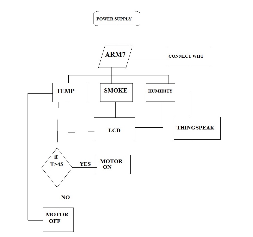
Fig.5.1. flowchart of smart environment
Environmental watching applications of the IoT typically use sensors to lend a hand in environmental protection by watching air or water quality, atmospherical or soil conditions and may even embody areas like watching the movements of life and their habitats. Development of resource unnatural devices connected to net conjointlyimplies that alternative applications like moving ridge or earthquake early warning systems may be utilized by emergency services to produce effective aid.
Theanalysis are administered for pollution owing to the changes within the parameters owing to Climate (Rain, Temperature, atmosphere, Dust) modification.
CHAPTER 6
ADVANTAGES, DISADVANTAGES AND APPLICATIONS
- ADVANTAGES:
Reliability
Ease of Operation
Useful to discover harmful gases
Can be used as electrolytic applicationsDISADVANTAGES:
The equiment is very sensitive.
We cannot confirm the gently weighted gases.APPLICATIONS:
Can be employed in Mines to discover the presence of dreadful gases.
In Public Places like searching mallsEtc,
This Project will be applied wherever Public Safety could be a Major Task.
In Hospitals and sensitive areas additionally this project will be enforced.
In Marine Applications
CHAPTER 7
RESULTS

Fig 7.1.temperature

Fig 7.2 smoke

Fig 7.3 Humidity
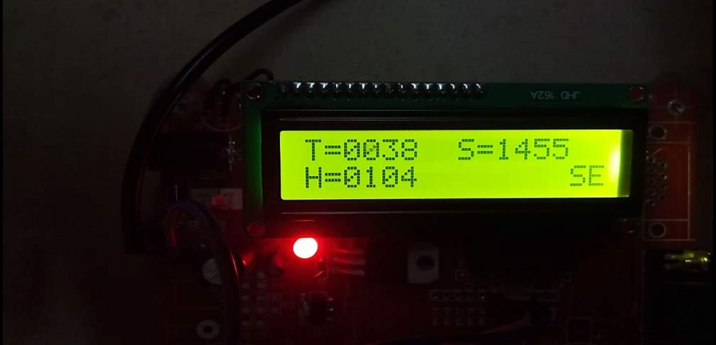
Fig.7.4 sending data to the server
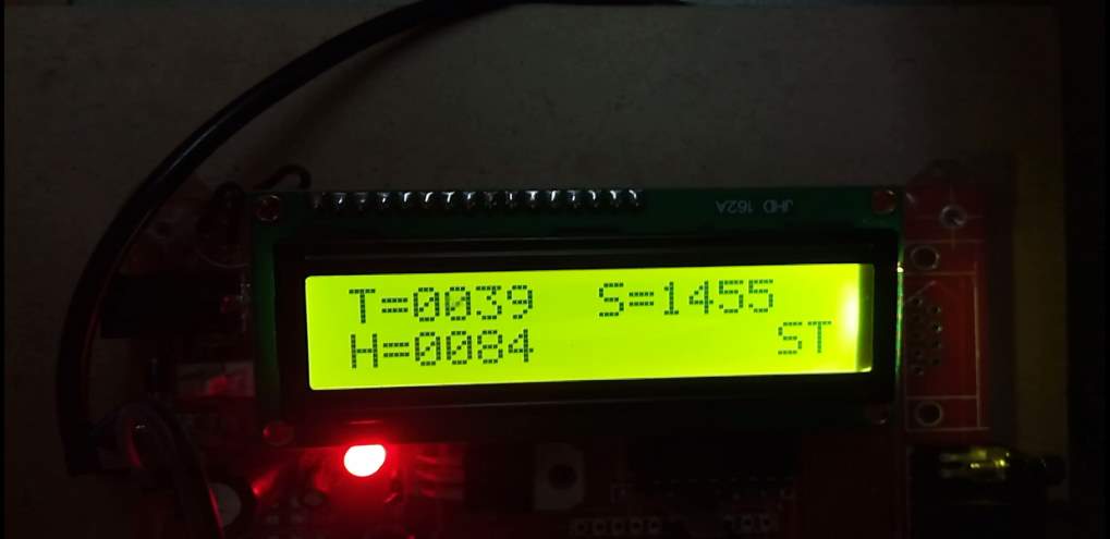
Fig.7.5 transmitted data
CHAPTER 8
CONCLUSION, FUTUREPROSPECTS
8.1 CONCLUSION:
Increasing environmental pollution is one of the tedious tasks since the humans are responsible for this hazardous nature which poses threat to whole world. And we are responsible to eradicate pollution problems. Virtually all emissions vary from time to time. Here we track temperature, smoke and humidity for every 50 seconds and monitor the differences using IOT.
It is an excellent concept that will show a new dimension in monitoring. Although the general and specific objective is very similar, the technological solutions employed are very different.
8.2 FUTURE WORK DEVELOPMENT
The information that is collected by the sensors could be used by the authorities to take necessary action such as emergency warning messages and evacuation of people to safe places. Further implementing pollution monitoring systems will help to assess how bad air pollution is from day to day and save the environment from further pollution.
8.3. APPENDIX
#include<LPC214x.h>
#include<string.h>
#include”lcd_busy.h”
#include”adc.h”
#include”int_char.h”
#include”ioline_set_clr.h”
#include”send_serial_data.h”
/////////////////////////////////////////////////
int main()
{
VPBDIV=0x01;
lcd_init();
lcd_init();
lcd_init();
Seril_Init(1 ,9600);
Com1_Int_Enable();
message(0x80,” WELCOME “);
delay(20000);
init(0x01);
while(1)
{
message(0xce,”SE”);
int_char_con(0x80,”T=”,(ADC1_Read()*3.3)/10);//p0.28
delay(50000);
send_data(1,”AT+CIPSTART=”TCP”,”184.106.153.149”,80 ”);
delay(50000);
delay(50000);
////////////////////////////////////////////////////////
send_data(1,”AT+CIPSEND=73 ”);
delay(50000);
send_data(1,”GET/update?api_key=G705AOELYHN9P9ZJ&field1=”);//44
t=1; s=0; h=0;
int_char_con(0x80,”T=”,(ADC1_Read()*3.3)/10);//p0.28
////////////////////////////////////////////////
if(((ADC1_Read()*3.3)/10)>45)
{
ioline_set(1,28,1);
ioline_set(1,29,1);
ioline_set(1,30,1);delay(30000);
}
else
{
ioline_set(1,28,0);
ioline_set(1,29,0);
ioline_set(1,30,0);delay(30000);
}
send_data(1,array_data);//4
send_data(1,”&field2=”);//8
t=0;
s=1;
h=0;
int_char_con(0x88,”S=”,300+(ADC2_Read()*3.3));//p0.29
send_data(1,array_data);//4
send_data(1,”&field3=”);//8
t=0;
s=0;
h=1;
int_char_con(0xc0,”H=”,15+(ADC3_Read()*3.3));//p0.30
send_data(1,array_data);//4
send_data(1,” ”); //1
message(0xce,”ST”);
delay(10000)
}
}
REFERENCES:
[1]https://www.google.co.in/search?site=&source=hp&q=internet+of+things+&oq=internet+of+things+&gs_l=hp.3..0l10.5126.6970.0.8572.8.8.0.0.0.0.127.774.2j5.7.0….0…1c.1.64.hp..1.6.646.0.eDr_RX5dyiI
[2]http://www.governancenow.com/views/interview/ternet-things-has-a-large-role-playsmart-cities
[3]http://ieeexplore.ieee.org/stamp/stamp.jsp?arnumber=6740844
[4]https://en.wikipedia.org/wiki/Internet_of_Things#Environmental_monitoring
[5]http://www.ijetcse.com/wpcontent/plugins/ijetcse/file/upload/docx/889Smart-Device-to-monitor-water-quality-toavoidpollution-in-IoT-environment-pdf.pdf
[6]http://www.ijaiem.org/volume2issue7/IJAIE M-2013-07-14-041.pdf
[7]34TUhttp://eastwind.es/en/ibm-expands-its-airgreen-horizons-initiative-out-of-china/U34T International Journal of Scientific Engineering and Applied Science (IJSEAS) – Volume-2, Issue-3, March 2016 ISSN: 2395-3470 www.ijseas.com 265
[8]34TUhttp://www.ipcbee.com/vol32/009ICESE2012D033.pdfU34T
[9]Uhttps://www.google.co.in/search?q=images+for+controlling+air+pollution+using+iot&source=lnms&tbm=isch&sa=X&ved=0ahUKEwjnkLXvuKHLAhWOGo4KHb_DCw4Q_AUICCgC&biw=1280&bih=879#tbm=isch&q=images+for+controlling+pollution+using+iot&imgrc=zfQnUdlgpPyWOM%3AU [10]34TUhttps://en.wikipedia.org/wiki/Cloud_storageU34T [11]34TUhttps://en.wikipedia.org/wiki/Cloud_storage#AdvantagesU4
BIBLIOGRAPHY
The 8051 Microcontroller and Embedded Systems
– M.A Mazidi& J.G Mazidi
The Microcontroller Idea Book
– John Axelson
The Microcontroller Application Cookbook
– Matt Gilliland
Digital design – Morris Mano
Linear integrated circuits – RoyChoudary
Cite This Work
To export a reference to this article please select a referencing stye below:
Related Services
View all


Related Content
All TagsContent relating to: "Internet of Things"
Internet of Things (IoT) is a term used to describe a network of objects connected via the internet. The objects within this network have the ability to share data with each other without the need for human input.
Related Articles

DMCA / Removal Request
If you are the original writer of this dissertation and no longer wish to have your work published on the UKDiss.com website then please: