Advances in Solvent-Based Recovery Method for Heavy Oil Reservoirs
Info: 9821 words (39 pages) Dissertation
Published: 7th Sep 2021
Tagged: Environmental Studies
Abstract
Solvent-based methods have been studied for many years in the development of heavy oil or bitumen reservoir. Compared with the conventional thermal-based methods such as CSS and SAGD, the injection solvent is much more energy-saving and eco-friendly and particularly useful in thin reservoirs.
In this paper, some basic concepts and mechanisms of the solvent-based methods are reviewed. Viscosity, swelling factor, diffusion, dispersion, asphaltene precipitation and some criteria of solvent selection are discussed. Viscosity is the kernel mechanism, but none of the current viscosity mixing rules can accurately estimate the viscosity of the solvent-oil mixture. The mass transfer process in a solvent-based method depends on the diffusion and dispersion mechanisms, and several theoretical model and experimental measurement for diffusion and dispersion processes are reviewed. The effects of asphaltene precipitation is complicated that could give either a positive improvement of viscosity reduction or a negative influence of formation blockage.
Several solvent-based methods such as VAPEX, warm- VAPEX, ES-SAGD, SAS, ECSP and etc. are discussed. The thermal based solvent methods will give a larger recovery factor, while non-thermal solvent-based method will provide less CEOR. Co-injection of light hydrocarbons and steam will not provide a higher recovery factor than pure steam injection in SAGD process, however, the much reduced CEOR still make it feasible and economic.
Content
1 Introductions
There are tremendous heavy oil reservoirs over the world. Over 90% of the heavy oil resources are located in Canada and Venezuela [1]. In Canada, over 62% of the heavy oil resources are deposited in Saskatchewan, of which 3.4◊109 m3 are proved reserves [2]. However, the main difficulty existing in the development of these reservoirs is the thin thickness of the payzones. The payzones in over 90% of the proven reservoirs are less than 10 m and in 55% of the proven reservoirs are with a payzone of less than 5 m [3].
Conventional thermal methods such as CSS (cyclic steam stimulation) and SAGD (steam assisted gravity drainage) are inefficient for these thin reservoirs as the heat loss is both rapid and drastic. Huge amount of water would be consumed and lots of ecological problems might occur.
Compared with conventional thermal methods, solvent-based methods, especially the non-thermal VAPEX process, are proven to effective in the development of thin reservoirs [4-5]. Nevertheless, the solvent-based methods are also promising and advantageous in the development of relatively thick reservoirs because of its energy conservation. The solvent-based thermal methods take advantages of both the thermal mechanisms and solvent mechanisms, showing considerably high recovery factor. In this paper, the mechanisms of the solvent EOR and several solvent-based methods are reviewed.
2 Mechanisms
2.1 Viscosity reduction
The oil viscosity can be significantly reduced by the injection of solvent. Massive researchers have found that the oil dynamic viscosity was a power law function with respect to the solvent concentration. Figure 2-1 shows the effect of solvent concentration on oil dynamic viscosity.
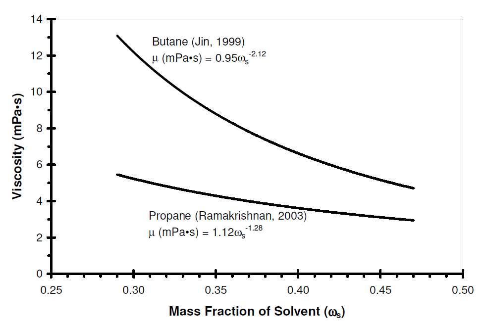
Fig. 2-1 Effect of solvent concentration on oil dynamic viscosity [22]
The viscosity of solvent-oil mixture is determined by several elements such as temperature, pressure and the fractional volume of each component. Experimental method is the most common and accurate way to obtain the mixture viscosity at different conditions. Besides that, a lot of viscosity blending model were also proposed to estimate the mixture viscosity.
Some typical viscosity mixing rules are listed in Table 2-2~2-4. The nomenclatures are shown in Table 2-1
Table 2-1. Pure mixing rules and mixing rules with viscosity blending index [18]
| Author | Equation |
| Arrehnius | μ=μAxAμBxB
logμ=xAlogμA+xBlogμB |
| Bingham | 1μ=xAμA+xBμB |
| Kendall and Monroe | μ1/3=wAμA1/3+wBμB1/3 |
| Linear | μ=xAμA+xBμB |
| Cragoe | μ=5×10⁻⁴e(1000ln20L)
L=wAμA+wBμB |
| Reid | v=(xA+xB)vAvBxAvA+xBvB |
| Chirinos | loglogv+C=wAloglogvA+C+wBloglog(vB+C)
C=0.7 |
| Refutas index method | VBIi=23.097+33.469loglogvi+0.8
VBIβ=wAVBIA+wBVBIB v=1010(VBIβ-23.09733.469)-0.8 |
| Chevron | VBIi=logvi3+logvi
VBIβ=∑i=1nxiVBIi μ=10(3VBIβ1-VBIβ) |
Table 2-2. Mixing rules with a binary interaction parameter [18]
| Author | Equation |
| Van der Wyk | lnv=mA2lnvAvBvAB+2mAlnvABvB+lnvB |
| Grunberg and Nissan | lnμ=mAlnμA+mBlnμB+mAmBGAB |
| Tamura and Kurata | logv=mAvAxA+mBvBxB+2vAB(mAmBxAxB)0.5 |
Table 2-3. Mixing rules with additional parameters [18]
| Author | Equation |
| Walther | loglogv+C=xAloglogvA+C+xBloglogvB+C |
| Latour | v=e(ea1-wBn+lnvB-1)
a=ln(lnvA-lnvB+1) n=vB0.9029vB+0.1351 |
| Lederer | lnμ=xA’lnμA+xB’lnμB
xA’=αxAαxA+xB xB’=1-xA’ μμB-1=αlnμAμBxA |
| Chung et al. | α=0.255SG-4.161.8T547.571.85(e7.36-e7.36(1-p/7384)e7.36-1) |
| Shu | α=17.04∆ρ0.5237ρA3.2745ρB1.6316ln(μAμB) |
| Barrufet and Setiadarma | α=0.35242695mB-71154 |
| Ishikawa | μAμB-1=[KvμAμB]vB |
| Lobe | v=ϕAvAeϕBαB+ϕBvBeϕAαA
αA=-1.7lnvAvA αA=0.27ln(vBvA)+(1.3ln(vBvA))1/2 ϕA=mAVAmAVA+mBVB ϕB=mBVBmAVA+mBVB |
| Power law | μn=wAμAn+wBμBn |
| Panchenekov | v=Asρ4/3T1/2(e(ε/RT)-1) |
| Lima | loglogv=ρ[mAIA+mBIBmAMA+mBMB] |
Table 2-4. Mixing rules with an excess function [18]
| Author | Equation |
| Ratcliff and Khan | (lnv)id=∑wilnvi
(lnv)real=∑xilnvi±(lnv)E (lnv)E=aABwAwB |
| Wedlake and Ratcliff | lnμ=lnμid+βE
lnμid=∑wilnμi βE=βS+βG |
G Centeno et al.[6] applied seventeen of the mixing rules listed above to predict kinematic viscosity of the crude oil-diesel mixture. The results indicated a general trend to fail as the crude oil API gravity decreased, although at high temperature of analysis the predictions improved. No rule was capable of estimating viscosity for all the crude oils, highlighting that predicting viscosity is a challenging task.
H Li and D Yang [7] used Arrehnius, Cragoe, Chung, Shu and Lobe methods to predict the viscosity of heavy oil diluted by propane and/or butane. The comparison of the prediction and experimental results indicated that only Lobe method provided a result with the same magnitude with the measured viscosity, while other four methods demonstrated large deviations from the measured viscosity.
Viscosity reduction is the main mechanism of the solvent-based method. Although it is apparent that the injection of solvent can reduce the viscosity and increase the mobility of the reservoir fluid, it is still a challenge to accurately predict the exact degree of the viscosity decline with the solvent addition.
2.2 Swelling effect
Besides the viscosity reduction, the swelling effect is also an important mechanism of the solvent EOR. Swelling causes a fraction of trapped oil to flow owing to mass transfer based volume expansion within the reservoir. The swelling factor of solvent-saturated oil is defined as equation (2-5) [8]:
SF=Vs2Vs1×11-X
(2-5)
Where:
SF
is swelling factor.
Vs1
is molar volume of heavy oil at saturation temperature and atmospheric pressure.
Vs2
is molar volume of solvent-saturated heavy oil at saturation temperature and saturation pressure.
X
is solvent solubility in heavy oil in mole fraction.
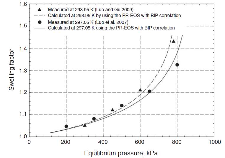
Fig. 2-2 MeasuredSF and calculated SF for propane-heavy oil system [9]
2.3 Diffusion
Diffusion refers to the migration of molecules from high concentration area to low concentration area. Diffusion is a very important process for the solvent EOR as the solvent molecules are absorbed and mixed with the heavy oil during the diffusion process. The concentration of the solvent in heavy oil cause the viscosity reduction, which will significantly improve the mobility of the heavy oil.
The diffusion process is commonly characterized by the Fick’s Law, which is expressed as the equation (2-6).
∂c∂t=D∙△c
(2-6)
Where,
cis the concentration and
Dis the diffusion coefficient.
For heavy oil reservoirs, the diffusion process or diffusion coefficient of the solvent determines the amount and injecting rate of the injected solvent, the extent of the viscosity reduction of the heavy oil, the soak time for the solvent to reduce the viscosity to the desired extent and the production rate of the oil.
The measurements of the diffusion coefficient can be categorized into two types: intrusive method and non-intrusive method [11].
Intrusive methods are to analyze the composition of solvent-heavy oil system at different locations and times and the composition analysis requires taking liquid samples out of the solvent-heavy oil mixture. This method is expensive and time-consuming. Besides, the experimental error of this method is relatively high [11].
Non-intrusive methods measure the change of a particular property such as volume, pressure, solute volatilization rate, position of the gas liquid interface, and nuclear magnetic resonance of the solvent-heavy oil system during the molecular diffusion process.
The pressure decay method [12-16] is the most widely used non-intrusive method to calculate the diffusion coefficient. The experimental setup is a closed high-pressure PVT cell. The pressure of the solvent-heavy oil system decreases as the solvent diffuses into the oil, the data of the pressure versus time is recorded for calculation. Simplicity is the main merit of this measurement. However, its accuracy is strongly dependent on the diffusion model selected to implement the calculation. The assumed boundary conditions have significantly impacts on the results.
Other non-intrusive methods include dynamic pendant drop volume analysis [16], oil phase swelling test [12,15]. Similarly with the pressure decay method, the accuracy of those m`ethods are subject to the model and boundary conditions.
Recently, some methods based on imaging or scanning are more and more applied to measure the diffusion coefficient such as magnetic resonance imaging (MRI) [17], nuclear isotope tracking, low-field nuclear magnetic resonance spectra (NMR) [18] and X-ray computed tomography scanning [19].
In 2016, Li and Yang [20] developed a method to determine the individual diffusion coefficients of solvent/ CO2 mixture in heavy oil with pressure-decay method. In this method, the Fick’s law in n-components is described as [21]:
∂ci∂t=∑j=1n-1Dij∙△cj
(2-7)
Where
ci,
cjis concentration of the ithand jth component, respectively.
Dijis the so-called “cross-term” diffusion coefficient that is usually 10% or less of the bottom of the main terms [21].
Therefore, for a ternary system, equation (2-7) can be expressed as:
∂c1∂t=D11∙∂2c1∂x2+D12∙∂2c2∂x2∂c2∂t=D21∙∂2c1∂x2+D22∙∂2c2∂x2
(2-8)
The initial condition:
ci=0, 0≤x≤L0, t=0,i=1, 2
(2-9)
Where
L0is the initial height of the heavy oil.
Bottom boundary condition (Neumann equilibrium boundary condition):
∂ci∂t=0, x=0, t>0,i=1, 2 (2-10)
Intherfical boundary condition (Dirichlet quasi=equilibrium boundary condition):
ci=ci,sat[P(t)], x=L(t), t>0,i=1, 2 (2-11)
Where
ci,satis the saturation concentration of the component i.
P(t)and
L(t)can be measured during time during time. And
ci,satcan be determined by two-phase flash calculations for the overall feed at the given temperature and pressure. One should note that this statement is only valid when the feed is found to be unstable and phase split calculation is required. Applying the PR-EOS with volume translation, the coefficient can be determined by the procedures shown in Fig. 3-3.
∂c∂t|m,n=cmn+1-cmn∆t (2-12)
∂2c∂x2|m,n=cm+1n-2cmn+cm-1n∆x2 (2-13)
Where,
mis the mthnode along the x-direction and
nis the nth time step.
This method can calculate the individual diffusion coefficient in a solvent mixture. And the diffusion behavior of each component of the mixture can be predicted accurately. As the solvent mixture is commonly used in the solvent-based method, it is imperative to determine the individual diffusion coefficient of each component in a mixture.
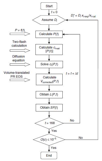
Fig. 2-3 Procedures for determination of the individual diffusion coefficients [20]
The diffusion coefficients are highly dependent on the pressure, temperature and concentration. In general, the diffusion coefficient increases with temperature at a given concentration and pressure, and increases with pressure at a given concentration and temperature [22]. The relation between diffusivity and concentration is much more complicated. Massive studies indicated an inverse relationship between the diffusion coefficient and the viscosity [23].
D=αμβ
(2-14)
It should be noted that viscosity is a function of solvent concentration, in which the viscosity decreases with the concentration. This equation demonstrates that the solvent diffusivity will increase with the concentration. However, Upreti [24] correlated the concentration-dependent diffusivity of gaseous CO2, CH4, C2H6, and N2 in Athabasca bitumen and the result shows that diffusivity increases with concentration to a peak value before decreasing.
2.4 Dispersion
Dispersion is also known as the effective diffusion, which is a combination of the molecular diffusion and convective flow [24]. The flow of the bulk phase will significantly accelerate the mass transfer process. Some earlier mass transfer model based on the molecular diffusion could hardly explain the high production rate in in porous media. Therefore, dispersion or effective diffusion was introduced to account for this phenomenon.
The dispersion process can be divided into longitudinal dispersion and transverse dispersion. Longitudinal dispersion is a process that the dispersion spread along with the bulk phase flow, while the direction of transverse dispersion is perpendicular to the direction of the bulk phase flow [25].
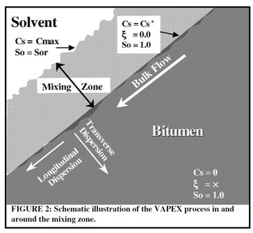
Fig. 2-4 Transverse and longitudinal diffusion [32]
The mass transfer in a dynamic process is the summation of both the diffusion and dispersion. Taylor dispersion [26] can be used to characterize the dispersion in a capillary. In this theory, the flow in the capillary is considered as laminar flow, which takes the form as:
u(r)=u0(1-r2R2)
(2-15)
Where
Ris the radius of the capillary,
ris the distance from the center of the capillary,
u(r)is the velocity at the distance
rand
u0is the maximum velocity at the center of the capillary.
The concentration of the dissolved matter is assumed to be symmetric around the axis of the capillary, then the diffusion equation can be written as equation (2-16).
D(∂2c∂r2+1r∂c∂r+∂2c∂x2)=∂c∂t+u0(1-r2R2)∂c∂x
(2-16)
The convective velocity is assumed to be the average velocity of the flow, which is equal to half of the maximum velocity.
dxdt=u02
(2-17)
Flow rate of the rate of transfer of solute concentration
Q=-πR2u04192D∂cm∂x
(2-18)
The longitudinal dispersion coefficient is expressed as the follow equation:
kl-D=R2u2192D
(2-19)
For dispersion in fractures such as in a Hele-Shaw model, the equations for the longitudinal and transverse dispersions, which are proposed by Perkins and Johnston [27], can be expressed as follows:
klD=1Fϕ+ClUdpσD
(2-20)
ktD=1Fϕ+CtUdpσD
(2-21)
Where
kland
ktare dispersion coefficients for longitudinal and transverse processes, respectively.
Dis diffusion coefficient,
Fis formation resistivity factor,
ϕis formation porosity,
Uis fluid velocity in the direction of bulk flow,
dpis particle diameter and
σis inhomogeneity factor.
These two equations are both comprised of two terms: term
1Fϕaccounting for the diffusion process and term
UdpσDaccounting for the dispersion process. The parameters
Cland
Ctare constants which should be determined by experiments.
Cland
Ctare respectively equal to 0.5 and 0.0157 in sand packs or bead packs according to Blackwell’s laboratory tests [28].
When applying a 2-D model to characterizes the dispersion coefficient, it should be noted that the effect of transverse dispersion due to the x-vector velocity is in the same direction as the longitudinal dispersion along the y-vector. The 2-D equations for longitudinal and transverse dispersions are shown as follows [25]:
kxD=1Fϕ+ClUxdpσD+CtUydpσD
(2-22)
kyD=1Fϕ+ClUydpσD+CtUxdpσD
(2-23)
When the flow velocity is equal to 0, the dispersion coefficients will reduce to the diffusion coefficients in porous media. The convective velocity can be determined by the combination of the momentum balance for bulk phase (heavy oil) and mass balance for solvents. Darcy’s law and Fick’s law are used for this calculation.
2.5 Asphaltene precipitation
The components of heavy oil can be separated into four groups, saturates, aromatics, resins, and asphaltenes, which is also known as the SARA fractions [29]. Asphaltenes are comprised of polar and high-weight molecules, including condensed aromatic rings, naphthenic rings and heteroatoms.
Asphaltene is soluble in carbon tetrachloride, carbon disulfide and aromatics, but not soluble in lighter paraffins such as propane and butane [30]. This particular property will cause asphaltene precipitation, which is also known as de-Asphalting, in the solvent extraction process. As other components of the heavy oil dilute by the injected propane or butane, the asphaltene precipitation will take place at a certain point. The concentration of solvents at this point is called critical concentration [9].
The critical concentration varies from heavy oil to heavy oil. Bulter and Jiang [31] indicated that the critical concentration of the propane ranges from 20 to 30 wt.%. Ramakrishnan’s experiment showed that the asphaltene precipitation wasn’t observed even though the concentration of propane in oil is over 30 wt.% [32]. In the Li and Yang’s work [7], in a butane-heavy oil system, no significant asphaltene precipitation was observed although the content of the butane reached 36.2%.
The amount of the asphaltene precipitation mainly depends on four factors: solvent type, temperature, solvent concentration and contact time. For non-polar solvents, a solubility parameter is defined to characterize the ability of a solvent to dissolve asphaltenes, which is given by equation (2-24) [33]:
β=γV1/3
(2-24)
Where,
βis solubility parameter,
γis surface tension and
Vis molar volume. It is apparent that there is an inverse relationship between the solubility parameter and asphaltene precipitation. Mitchell and Speight studied the relationship between the solvent type and Athabasca bitumen, different solvents were first mixed with the oil with equal volume ratio [30]. The experimental result is shown as Fig. 2-5.
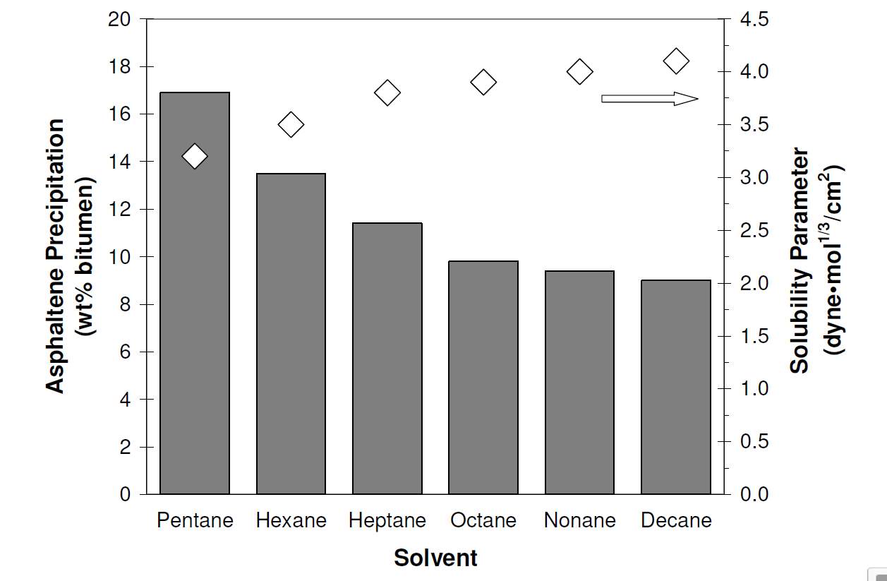
Fig. 2-5 The relationshipbetween solubility parameter and asphaltene precipitations
The effect of asphaltene precipitation in solvent-based process is separated into two contrary aspects, the positive one of further viscosity reduction and the negative one of permeability decline.
1) Viscosity reduction:
As the highly viscous asphaltene component precipitates, the oil viscosity will be further reduced. The relation between solvent injection pressure and oil viscosity is shown as follows. Haghigat and Maini investigated the effect of asphaltene precipitation, the relationship between the pressure of solvent injection and the oil viscosity is illustrated in Fig.2-6 [34]. The viscosity is drastically reduced when the pressure reaches a certain point, which represents the concentration of the solvent reaches the so-called critical concentration.
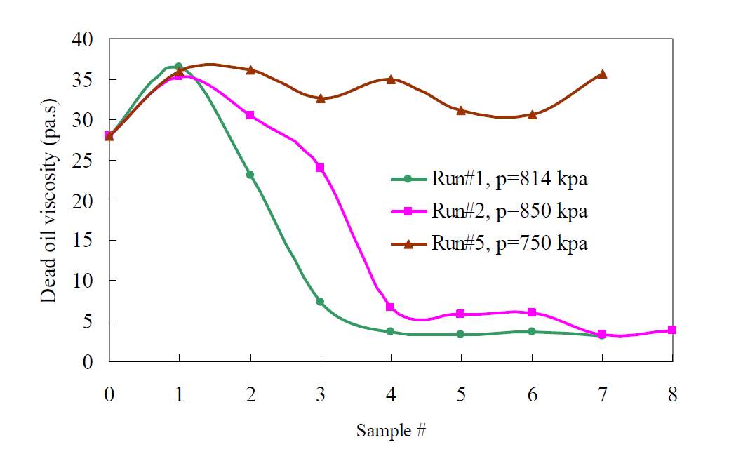
Fig. 2-6 The relationship between the pressure of solvent injection and the oil viscosity
2) Permeability decline.
Although the de-asphalting will significantly reduce the viscosity, the asphaltene deposition can also block the formation, reducing the permeability greatly. Due to the diffusion and dispersion process, the precipitation reaction is more likely to occur at the interfacial area, where the concentration of the solvents is at the maximum level. Fig.2-7 illustrates the fringe pattern of the precipitation distribution in a Hele-Shaw cell. In this solvent extraction experiment, the asphaltene depositions remain as the interface moves[35].
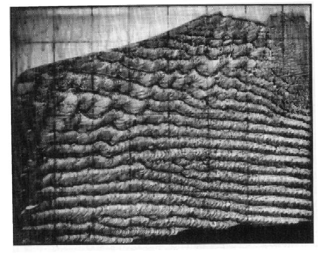
Fig. 2-7 Asphaltene depositions in Hele Shaw cell
The formation will be severely blocked by the asphaltene depositions, causing the permeability reduction. Although the viscosity of the oil is greatly reduced, the mobility could decrease rather than increase due to this counteraction. Haghigat and Maini indicated that the formation damage due to asphaltene precipitation would reduce or even kill the oil production [34].
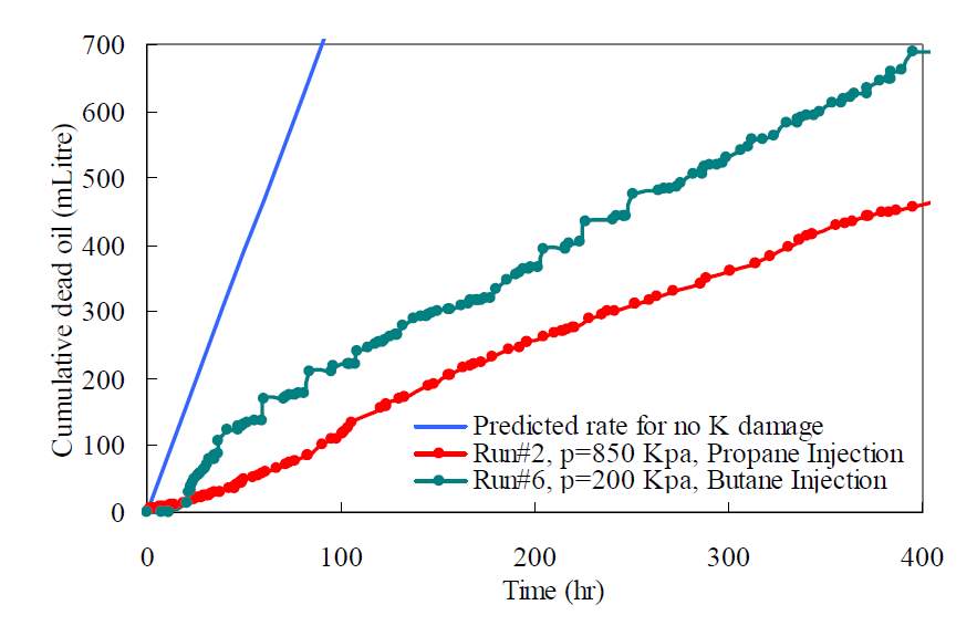
Fig. 2-8 Formation damage due to asphaltene precipitation
2.6 Solvent selection
The selection of a solvent should consider the following factors: condensation point, molecular weight, solubility, diffusivity, and reservoir temperature and pressure [32].
Generally, a vaporized solvent with low molecular weight and near or at its dew point at reservoir conditions are recommended. There are several advantages listed as follows.
1) Near the dew point, the vaporized solvent has the maximum solubility in the heavy oil [36].
2) Near the dew point, the higher solvent concentration can cause asphaltene precipitation, which will further reduce the viscosity of the heavy oil [37].
(3) Low molecular weight means higher density difference between the solvent and heavy oil, which gives a higher driving force in gravity drainage process [37].
4) To maintain the same pressure, the consumption of the vaporized solvent is far lower than the consumption of the liquid solvent [37].
5) It is easy and energy-efficient to flash separate the solvent from the produced oil and recycle [37].
The most widely used solvents such as propane or butane might condense under reservoir conditions. This condensation phenomenon greatly increases the consumption of the solvents and reduces the density difference between the solvent and heavy oil, which particularly gives a negative effect on gravity drainage process. Das and Butler indicated that the required amount of liquid propane is 25 times of the amount of gases propane to maintain a same pressure at a given temperature.
Non-condensable gases (NCG) [10] are usually co-injected with the solvents to adjust solvent dew point. At a given injection pressure, the co-injected NCG reduces the partial pressure of the solvents, preventing the solvents condensation. CO2and methane are the most commonly used NCG. Besides their non-condensable property, they can also participate in the extraction process although they are not as effective as propane and butane. The use of CO2 and light hydrocarbons such as methane can also significantly reduce the cost of the development as they are less expensive than pure solvents such as propane and butane.
However, there are still disadvantages when co-injecting NCG. The first one is that the solvents have to diffuse through the co-injected NCG to reach the heavy oil. The second disadvantage is that concentration of the solvent is reduced, which decreases the mass transfer speed [37].
3 Solvent-based methods
3.1 VAPEX
The vapor extraction (VAPEX) [4] was first proposed by Butler and Mokrys in 1989. In this method, two horizontal wells are set in the reservoir as shown in figure 3-1. Vaporized solvents are injected thorough the top well and the injected solvents will form a solvent vapor chamber due to the high pressure.
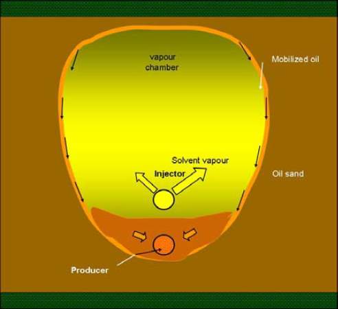
Fig.3-1 Mechanisms of VAPEX process [1]
The solvents will dissolve into the oil in the vapor chamber boundary. As the viscosity of the oil in the boundary is highly reduced, the oil-solvent mixture drains down into the production well due to gravity. As more solvents diffuse and disperses into the oil and more oil-solvent mixture are produced, the chamber expands and sweeps more area of the reservoir.
The mechanisms of VAPEX EOR process are mainly ones which are discussed in chapter 3. The drive force of this process is the gravitational force. When the viscosity of the formation fluid is reduced to a certain extent, the effect of the gravity well exceeds that of viscous force, making the oil-solvent mixture start to flow.
The production rate of the VAPEX can be predicted the equation (3-1), which was proposed by Butler and Mokrys’s Hele-Shaw cell experiment [50].
Q=2Kgϕ∆SoNsh
(3-1)
Where
Kis permeability,
gis gravitational acceleration,
ϕis porosity,
∆Sois the change in oil saturation,
his the drainage height and
Nsis the dimensionless number defined as:
N=∫cmincmax∆ρD(1-c)μcdc
(3-2)
Where
cis solvent concentration,
Dis intrinsic solvent diffusivity,
∆ρis the change in solvent density and
μis viscosity.
When considering the VAPEX process in a heterogenous porous media, equation (3-3), which is a modified form of equation (3-1) was proposed by Jiang in 1996 [31].
Q=2K¯gϕΩ∆SoNsh
(3-3)
In this equation,
Ωis an index of porosity representing the cementation factor and
K¯is the average permeability given by:
K¯=1h∫0hKdz
(3-3)
Compared with the SAGD method, VAPEX process is much more energy-saving and eco-friendly. Solvents can be recycled and re-injected into the formation and the development cost decrease over time.
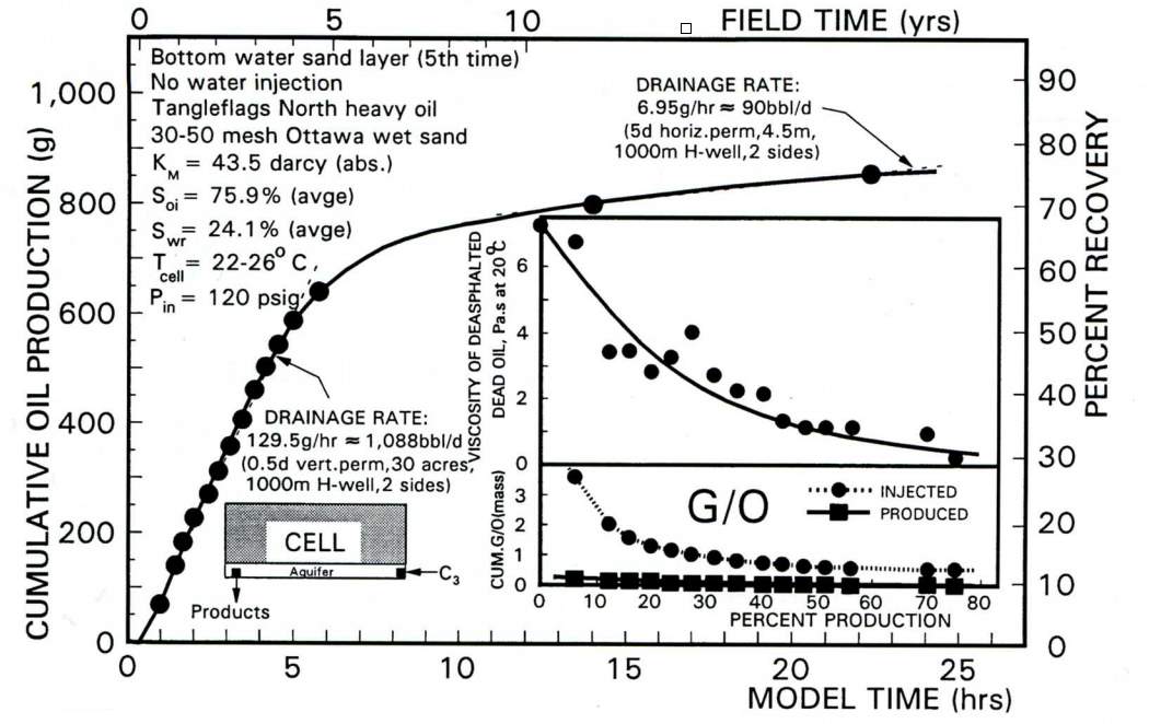
Fig.3-2 The change of cumulative oil production and recovery factor with time [2]
3.2 TSR
TSR (Thermal solvent reflux) method is a modification of the VAPEX method. In this method, heat stimulation is introduced through production well as shown in Fig.3-3.
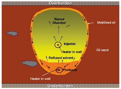
Fig.3-3 Mechanisms of thermal solvent reflux [40]
TSR method was first proposed by Frauenfeld [39] and coworkers at the Alberta Research Council (ARC) in 2005. In general, the heating stimulation method of TSR includes steam injection (or hybrid VAPEX) and electrical heater. In electrical heating based TSR, electrical heater is set inside the well to heat the reservoir fluid near the wellbore. According to Frauenfeld and Ivory’s experimental results, the recovery factor and CEOR (cumulative energy required for cumulative oil volume recovered) are both improved compared with the VEPAX process, furthermore, TSR with steam injection (or hybrid VAPEX) was much more efficient than that with electrical heater.
In TSR method, the introduced heat vaporizes the solvent produced with the oil back to the formation, improving the efficiency of solvent recycling. There are another two improvements compared with the normal VAPEX. Firstly, the introduced heat can further reduce the viscosity and increase the mobility of the reservoir fluid. Secondly, the high temperature increases the dew point of the injected solvent and significantly prevents the solvent condensation.
3.3 N-Solv® & Warm-VAPEX
In the N-Solv® and warm VAPEX methods, the solvent is heated previously before injection into the reservoir. N-Solv® was patented by Nenninger et al. in 2008 and warm VAPEX method was first pioneered by James in 2003 [41].
N-Solv® and warm VAPEX process are very similar methods. In N-Solv® process, the solvent is injected into the reservoir at the dew point, while the solvent is previously superheated before injection in warm-VAPEX process. Both of these two methods are less vulnerable to condensation phenomenon, which could reduce the efficiency of solvent dissolution.
The latent heat introduced by both method will further reduce the oil viscosity and accelerate the speed of diffusion and dispersion.
3.4 ES-SAGD
The expanding solvent steam assisted gravity drainage process (ES-SAGD) is similar with VAPEX. Two horizontal well are set in the formation, the top one is the injection well and the bottom one is the production well. In the ES-SAGD process, the solvent was co-injected with the steam vapor, which is the main difference with the VAPEX process. In fact, the ES-SAGD method was the prototype of VAPEX process established by Butler. Apparently, ES-SAGD is a thermal method, it is combination of pure VAPEX and SAGD.
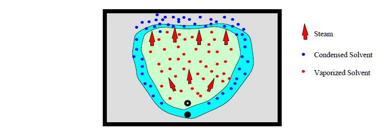
Fig.3–4 Mechanisms of ES-SAGD [1]
Compared with SAGD method, the advantages of ES-SAGD are listed as follows.
- Low SOR. The steam oil ratio of ES-SAGD is much lower than the normal SAGD, making this process energy-saving and economic.
- High production rate. In the ES-SAGD process, solvent is pushed by the steam and condenses in the boundary of vapor chamber. The viscosity of the oil is further reduced due to the combination of thermal and solvent effect.
In an idea case, the solvent can prevent the steam to condense, while the steam provides the expanding force of the vapor chamber. Compared with VAPEX process, the high temperature provide by the steam can maintain the solvent in the vapor phase and accelerate the velocity of diffusion and dispersion. The EOR mechanisms of the steam and solvent are both magnified due to this interaction.
For ES-SAGD process, the type and fraction of the solvent one of the determinants of the EOR efficiency. The variation of the oil drainage rate with different type of solvent is shown in Fig. 3-5.
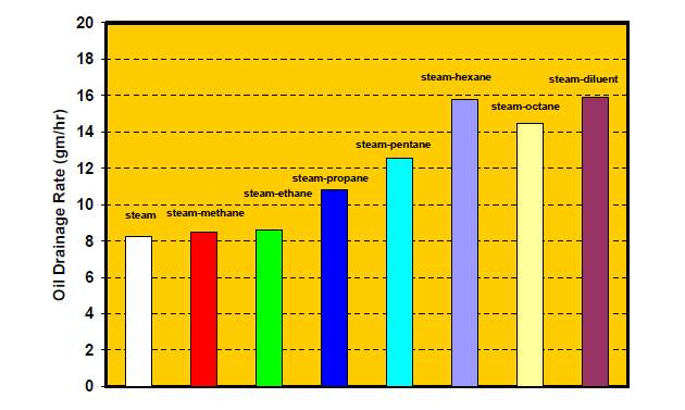
Fig.3–5 Effect of different solvent assisted steam[1]
Massive researches showed that the hydrocarbon solvent with low carbon number will not improve the ES-SAGD effect. W Li and D Mamora [42] found that the combination of light hydrocarbon (C1~C3) solvents and steam may reduce the recovery factor compared with pure steam injection (Fig.3-5). The optimal concentration of solvent was also studied with the analysis of CEOR (cumulative energy required for cumulative oil volume recovered). Results illustrated in Fig. 3-6. showed that a relatively low concentration 7~9% provided the best performance.
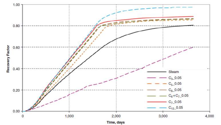

Fig. 3–6 EOR and CEOR of different solvent in SAGD process [54]
M. Ardali et al. indicated that the oil recovery and thermal efficiency could be improved by solvent heavier than butane in Athabasca reservoir. However, the CEOR increased as the heavier solvent was selected [43].
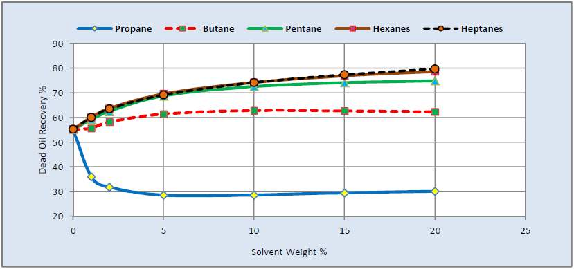
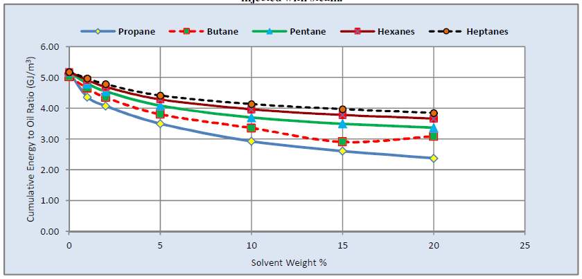
Fig. 3–7 EOR and CEOR of different solvent in SAGD process [55]
C Egboka and D Yang investigated the performance of ES-SAGD process with solvents of CO2, C3H8 and C4H10. The simulation results demonstrated that C4H10 provided the best EOR performance while CO2 provided the worst EOR performance in ES-SAGD process. The recovery factor decreased with the fraction of solvent or solvent-mixture increased. Although the recovery was decreased by the solvent injection, the significant CEOR reduction still made the light hydrocarbon solvent injection feasible in practice [44].
Table 3-1 Oil recovery for different solvent additives in SAGD process [44]
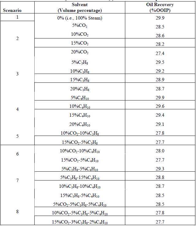
The optimal type and concentration of the solvent varies in different kinds of reservoirs. In a nutshell, light hydrocarbon or CO2 will reduce the oil recovery, while the ratio of cumulative energy consumed to cumulative oil recovered will increase with the number of carbon. A balance between the EOR and CEOR should be considered and verified carefully in the field practice.
3.5 SAS and SAVEX
SAS (Steam Alternating Solvent process) was proposed by L Zhao in 2004 [45]. The well configuration of this method is same as the methods mentioned above. The intention of this method is to combine the advantages of the SAGD and VAPEX processes to minimize the CEOR. In a nutshell, the SAS process is to inject steam and solvent alternately.
The viscosity reduction is more significant in SAGD rather than in VAPEX because of the large latent heat of superheated steam. However, the oil saturation and relative permeability of the chamber boundary in VAPEX method is much higher than that in SAGD method due to the relatively higher viscosity and absence of water. The core concept of the SAS is to combine the advantages of the higher relative permeability of oil in VAPEX and the lower viscosity reduction of oil in SAGD by means of alternately injecting solvents and steam. The solvent can prevent the steam intruding into the formation too fast, and the steam can heat the solvent and oil to further reduce the viscosity and accelerate the diffusion and dispersion. L Zhao’s numerical simulation results demonstrated that the production rate of SAS is higher than SAGD and much higher than VAPEX [45].
SAVEX (Combined steam and vapor process) is another modification of the SAGD method, which was patented by Gutek et al. in 2001 [46]. The difference between the SAVEX and ES-SAGD methods is the injection sequence. The SAVEX method starts with the normal SAGD process, when the oil recovery by SAGD reaches some economic balance point, the solvent is injected to further recover the residual oil.
3.6 SAP
SAP (Solvent aided process) was similar to ES-SAGD, which was proposed by Gupta in 2003 [47]. Light hydrocarbons are the solvents applied in SAP method, although they proved to probably reduce in oil recovery. SAP method takes the advantage of the heat-insulating property of the light hydrocarbons. The solvent injection timing is the key factor of the SAP method. Gupta indicated that the light solvent injected in the early stage could ride over the steam saturated region as an insulating layer, which reduces the heat loss of the reservoir [47]. This phenomenon would produce higher viscosity and lower temperature at the top of the steam chamber, which induces the chamber to develop horizontally and sweep over a larger region.
Fig. 3–8 Light solvent riding over the steam saturated region as an insulating layer [48]
3.7 CSP and ECSP
CSI (cyclic solvent process) and ECSP (enhanced cyclic solvent process) are processes which is similar with the CSS (cyclic steam stimulation). The injected fluids are cold solvents such as hydrocarbons and carbon dioxide. CSI or ECSP can be applied as a following stimulation of CHOPS, in which the formed wormhole provides a channel for the solvent injection.
Because the injection and production processes are conducted in the same well, the rate and amount of the injection, injecting sequence (particularly for ECSP) and soak time are the factors influencing the performance of development.
ECSP is a modification of CSP. In ECSP process, different solvents are injected in a particular sequence while the solvents are injected at once in CSP process. Yadali Jamaloei indicated that the optimal sequence of injection for ECSP is to inject the volatile solvent slug before the more soluble solvent slug, in order to effectively take advantages of the mechanisms of viscosity reduction and gas drive [49].
Although the recovery factor of CSP and ECSP is relatively lower than the methods discussed above, they are still valuable especially as the following procedure of CHOPS.
3.8 LASER
LASER (liquid addition to steam for enhancing recovery) is a modification of CSS (cyclic steam stimulation). In this process, liquid hydrocarbons (C5+) are injected into the reservoir. The SOR in LASER process is much lower than that in CSS process, the oil viscosity is reduced by the combined effect of heat and hydrocarbon solvents.
LASER method was firstly experimentally tested by Leaute and pilot tested in Cold Lake reservoir in 2002 [50]. As an alternative method of CSS, LASER is particularly useful in the late cycles of CSS, of which the SOR is extremely high.
3.9 SOS-FR
SOS-FR (steam over solvent injection in fractured reservoirs) was first proposed by Babadagli in 2008 [50]. It was developed for the fractured heavy oil reservoirs, especially for oil-wet or carbonate reservoirs. Like other solvent assisted steam method, SOS-FR also takes advantages of both solvent injection and steam injection.
The main ideal of SOS-FR is to create some thermal and chemical turbulence to make the reservoir readjust and the oil will be expelled from the matrix to fractures [52].
The injection sequence of this method is steam, solvent, steam. Firstly, the heat brought by the injected steam cause the oil in the matrix expand and the oil with lower viscosity will flow into the fractures. Meanwhile, the steam imbibes into the matrix, condenses into water and occupies some pore volume. Secondly, the solvent is injected and diffuses into the oil phase in the matrix, hence the change of oil viscosity and density cause a gravity drainage. Finally, steam is injected again. The heat introduced by the steam will reduce the viscosity of the solvent-oil mixture and improve the swelling effect. More oil drains in this procedure and will be driven to the production well by the injected steam. Most of the solvent can be retrieved by the steam re-injection, reducing the cost of this method [52].
3.10 Hot Solvent injection.
Hot Solvent injection (HSI) was proposed by V Pathak et al. in 2010 [53]. Compared with other methods discussed above, this method is more straightforward and simpler. In V Pathak’s experiment, the heated solvent vapor was directly injected into the core plug. The experimental setup is shown as follow.
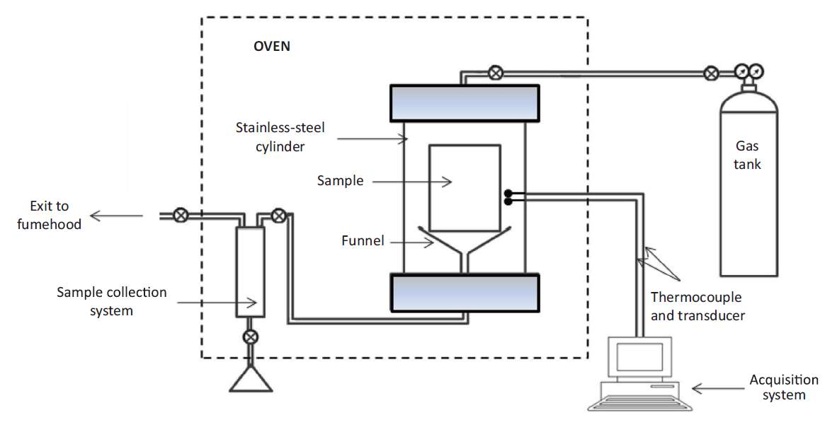
Fig. 3–9 Experimental setup for hot solvent injection process [53]
The main purpose of this experiment is to investigate the mechanisms of solvent in oil recovery. And all the mechanism discussed in chapter 3 can be observed at different levels in this experiment. Although this method has not been tested in field practice, it provides an idea especially for the post-CSP or ECSP development.
4 Conclusions
- PR EOS and several correlations of alpha function, BIP and volume translation were reviewed.
- Mechanisms of solvent-based methods were reviewed. Viscosity reduction is the core mechanism of the solvent based method. Diffusion and dispersion process determines the speed of the mixing process. Asphaltene precipitation could give both positive effect of viscosity reduction and negative effect of permeability decline. The solvent should be injected as a vapor phase into the reservoir.
- Different solved-based methods were reviewed. Thermal based solvent methods will give a larger recovery factor, while non-thermal solvent based method will provide less CEOR. Co-injection of light hydrocarbons and steam will not provide a higher recovery factor than pure steam injection in SAGD process, however, the much reduced CEOR still make it feasible and economic.
- CO2 as an important solvent for heavy oil recovery was not reviewed in this paper. (Insufficiency)
5 Acknowledgement
The author acknowledges the introductions and supports from Dr. DaoyongYang.
6 References
[1] Nasr, Tawfik Noaman, and Oluropo Rufus Ayodele. “Thermal techniques for the recovery of heavy oil and bitumen.” SPE International Improved Oil Recovery Conference in Asia Pacific. Society of Petroleum Engineers, 2005.
[2] Bowers, B., and K. J. Drummond. “Conventional Crude Oil Resources of the Western Canada Sedimentary Basin.” Journal of Canadian Petroleum Technology 36.02 (1997).
[3] Sahin, Secaeddin, Ulker Kalfa, and Demet Celebioglu. “Bate Raman Field Immiscible CO2 Application: Status Quo and Future Plans.” Latin American & Caribbean Petroleum Engineering Conference. Society of Petroleum Engineers, 2007.
[4] Butler, Roger M., and IGOR J. Mokrys. “A new process (VAPEX) for recovering heavy oils using hot water and hydrocarbon vapour.” Journal of Canadian Petroleum Technology 30.01 (1991).
[5] Butler, Roger M., and Igor J. Mokrys. “Recovery of heavy oils using vapourized hydrocarbon solvents: further development of the VAPEX process.” Journal of Canadian Petroleum Technology 32.06 (1993).
[6] Centeno, Guillermo, et al. “Testing various mixing rules for calculation of viscosity of petroleum blends.” Fuel 90.12 (2011): 3561-3570.
[7] Li, Huazhou, and Daoyong Tony Yang. “Phase behaviour of C3H8/n-C4H10/heavy-oil systems at high pressures and elevated temperatures.” Journal of Canadian Petroleum Technology 52.01 (2013): 30-40.
[8] Teja, Amyn S. “A Corresponding States equation for saturated liquid densities. I. Applications to LNG.” AIChE Journal 26.3 (1980): 337-341.
[9] Li, Huazhou, Sixu Zheng, and Daoyong Tony Yang. “Enhanced swelling effect and viscosity reduction of solvent (s)/CO2/heavy-oil systems.” SPE Journal 18.04 (2013): 695-707.
[10] Friedrich, Karen. “Effects of a Non-Condensable gas on the Vapex Process.” (2005).
[11] Guerrero-Aconcha, Uriel Enrique. The diffusion coefficient of liquid and gaseous solvents in heavy oil and bitumen. Diss. University of Calgary, 2009.
[12] Riazi, Mohammad R. “A new method for experimental measurement of diffusion coefficients in reservoir fluids.” Journal of Petroleum Science and Engineering 14.3 (1996): 235-250.
[13] Zhang, Y. P., C. L. Hyndman, and B. B. Maini. “Measurement of gas diffusivity in heavy oils.” Journal of Petroleum Science and Engineering 25.1 (2000): 37-47.
[14] Upreti, Simant R., and Anil K. Mehrotra. “Diffusivity of CO2, CH4, C2H6 and N2 in Athabasca bitumen.” The Canadian Journal of Chemical Engineering 80.1 (2002): 116-125.
[15] Tharanivasan, Asok Kumar, Chaodong Yang, and Yongan Gu. “Measurements of molecular diffusion coefficients of carbon dioxide, methane, and propane in heavy oil under reservoir conditions.” Energy & fuels 20.6 (2006): 2509-2517.
[16] Yang, Chaodong, and Yongan Gu. “A new method for measuring solvent diffusivity in heavy oil by dynamic pendant drop shape analysis (DPDSA).” SPE journal 11.01 (2006): 48-57.
[17] Fisher, Marc, and Gregory W. Albers. “Applications of diffusion–perfusion magnetic resonance imaging in acute ischemic stroke.” Neurology 52.9 (1999): 1750-1750.
[18] Wen, Y., A. Kantzas, and G. J. Wang. “Estimation of diffusion coefficients in bitumen solvent mixtures using X-ray CAT scanning and low field NMR.” Canadian International Petroleum Conference. Petroleum Society of Canada, 2004.
[19] Wen, Y. W., and A. Kantzas. “Monitoring bitumen-solvent interactions with low-field nuclear magnetic resonance and X-ray computer-assisted tomography.” Energy & fuels 19.4 (2005): 1319-1326.
[20] Li, Huazhou Andy, and Daoyong Tony Yang. “Determination of Individual Diffusion Coefficients of Solvent/CO2 Mixture in Heavy Oil With Pressure-Decay Method.” SPE Journal (2015).
[21] Cussler, Edward Lansing. Diffusion: mass transfer in fluid systems. Cambridge university press, 2009.
[22] Upreti, Simant R., and Anil K. Mehrotra. “Experimental measurement of gas diffusivity in bitumen: results for carbon dioxide.” Industrial & engineering chemistry research 39.4 (2000): 1080-1087.
[23] Hayduk, W., and S. C. Cheng. “Review of relation between diffusivity and solvent viscosity in dilute liquid solutions.” Chemical Engineering Science 26.5 (1971): 635-646.
[24] Upreti, S. R., et al. “Vapor extraction of heavy oil and bitumen: A review.” Energy & Fuels 21.3 (2007): 1562-1574.
[25] Boustani, A., and B. B. Maini. “The role of diffusion and convective dispersion in vapour extraction process.” Journal of Canadian Petroleum Technology 40.04 (2001).
[26] Taylor, Geoffrey. “Dispersion of soluble matter in solvent flowing slowly through a tube.” Proceedings of the Royal Society of London A: Mathematical, Physical and Engineering Sciences. Vol. 219. No. 1137. The Royal Society, 1953.
[27] Perkins, T. K., and O. C. Johnston. “A review of diffusion and dispersion in porous media.” Society of Petroleum Engineers Journal 3.01 (1963): 70-84.
[28] Blackwell, P. G. “Random diffusion models for animal movement.” Ecological Modelling 100.1 (1997): 87-102.
[29] Speight J G. The chemistry and technology of petroleum[M]. CRC press, 2014.
[30] Mitchell, David L., and James G. Speight. “The solubility of asphaltenes in hydrocarbon solvents.” Fuel 52.2 (1973): 149-152.
[31] Butler, R. M., and Q. Jiang. “Improved recovery of heavy oil by VAPEX with widely spaced horizontal injectors and producers.” Journal of Canadian Petroleum Technology 39.01 (2000).
[32] Ramakrishnan, Venkatesch. In-situ recovery of heavy oil by VAPEX using propane. Diss. University of Waterloo, 2003.
[33] Hildebrand, Joel H. “Solubility. Iii. Relative Values of Internal Pressures and Their Practical Application.” Journal of the American Chemical Society 41.7 (1919): 1067-1080.
[34] Haghighat, P., and B. B. Maini. “Role of asphaltene precipitation in VAPEX process.” Canadian International Petroleum Conference. Petroleum Society of Canada, 2008.
[35] Das, S. K., and R. M. Butler. “Effect of asphaltene deposition on the Vapex process: A preliminary investigation using a Hele-Shaw cell.” Journal of Canadian Petroleum Technology 33.06 (1994).
[36] Das, Swapan Kumar. In situ recovery of heavy oil and bitumin using vaporized hydrocarbon solvents. Chemical and Petroleum Engineering, University of Calgary, 1995.
[37] Das, Swapan K., and Roger M. Butler. “Mechanism of the vapor extraction process for heavy oil and bitumen.” Journal of Petroleum Science and Engineering 21.1 (1998): 43-59.
[38] Mokrys, Igor J., and Roger M. Butler. “The rise of interfering solvent chambers: solvent analog model of steam-assisted gravity drainage.” Journal of Canadian Petroleum Technology 32.03 (1993).
[39] Frauenfeld, T. W., et al. “Experimental and economic analysis of the thermal solvent and hybrid solvent processes.” Journal of Canadian Petroleum Technology 48.11 (2009): 55-62.
[40] Ivory, J., T. Frauenfeld, and C. Jossy. “Thermal solvent reflux and thermal solvent hybrid experiments.” Journal of Canadian Petroleum Technology 49.02 (2010): 23-31.
[41] James, Lesley. “Mass transfer mechanisms during the solvent recovery of heavy oil.” (2009).
[42] Li, Weiqiang, Daulat D. Mamora, and Yamin Li. “Solvent-type and-ratio impacts on solvent-aided SAGD process.” SPE Reservoir Evaluation & Engineering 14.03 (2011): 320-331.
[43] Ardali, Mojtaba, Daulat Debataraja Mamora, and Maria Barrufet. “A comparative simulation study of addition of solvents to steam in SAGD process.” Canadian Unconventional Resources and International Petroleum Conference. Society of Petroleum Engineers, 2010.
[44] Egboka, Chukwukadibia Ikechukwu, and Daoyong Tony Yang. “Performance of a SAGD Process with Addition of CO2, C3H8, and C4H10 in a Heavy Oil Reservoir.” SPE Heavy Oil Conference and Exhibition. Society of Petroleum Engineers, 2011.
[45] Zhao, Litong. “Steam alternating solvent process.” SPE International Thermal Operations and Heavy Oil Symposium and Western Regional Meeting. Society of Petroleum Engineers, 2004.
[46] Gutek, AM Harold, et al. “Combined steam and vapor extraction process (SAVEX) for in situ bitumen and heavy oil production.” U.S. Patent No. 6,662,872. 16 Dec. 2003.
[47] Gupta, S. C., and S. D. Gittins. “Christina Lake solvent aided process pilot.” Canadian International Petroleum Conference. Petroleum Society of Canada, 2005.
[48] Shafiei, A., et al. “Production technology selection for Iranian naturally fractured heavy oil reservoirs.” Canadian International Petroleum Conference. Petroleum Society of Canada, 2007.
[49] Yadali Jamaloei, Benyamin Ben. Enhanced Cyclic Solvent Process (ECSP) for Thin Heavy Oil Reservoirs. Diss. University of Calgary, 2013.
[50] Leaute, R. P., and B. S. Carey. “Liquid addition to steam for enhancing recovery (LASER) of bitumen with CSS: Results from the first pilot cycle.” Journal of Canadian Petroleum Technology 46.09 (2007).
[51] Al Bahlani, Al Muatasim Mohammad, and Tayfun Babadagli. “Laboratory and field scale analysis of Steam Over Solvent Injection in Fractured Reservoirs (SOS FR) for heavy oil recovery.” SPE Annual Technical Conference and Exhibition. Society of Petroleum Engineers, 2009.
[52] Al-Bahlani, A., and Tayfun Babadagli. “Steam-over-solvent injection in fractured reservoirs (SOS-FR) technique as a new approach for heavy-oil and bitumen recovery: an overview of the method.” Energy & Fuels 25.10 (2011): 4528-4539.
[53] Pathak, Varun, Tayfun Babadagli, and Neil Edmunds. “Mechanics of heavy-oil and bitumen recovery by hot solvent injection.” SPE Reservoir Evaluation & Engineering 15.02 (2012): 182-194.
Cite This Work
To export a reference to this article please select a referencing stye below:
Related Services
View all


Related Content
All TagsContent relating to: "Environmental Studies"
Environmental studies is a broad field of study that combines scientific principles, economics, humanities and social science in the study of human interactions with the environment with the aim of addressing complex environmental issues.
Related Articles

DMCA / Removal Request
If you are the original writer of this dissertation and no longer wish to have your work published on the UKDiss.com website then please: