Tribological Aspects in Design of Turbo-charger
Info: 8597 words (34 pages) Dissertation
Published: 9th Dec 2019
Tagged: Engineering
Table of Contents
2. EXPLODED VIEW OF TURBOCHARGER
3. KEY AREAS OF TRIBOLOGICAL FAILURES
3.1.1 Compressor Wheel and Compressor Nut Interface: –
3.1.2 Compressor Housing and Compressor housing bolts and retainer Interface: –
3.1.3 Compressor Housing and Compressor wheel Interface: –
3.2.1 Turbine Wheel shaft, Journal Bearing and bearing clips Interface: –
3.2.2 Turbine Wheel Shaft, Compressor seal, Turbine seal Interface: –
3.2.3 Turbine Wheel shaft, Thrust Bearing, Washer and Retainer Interface: –
3.3.1 Turbine Housing and Turbine housing bolts and retainer Interface: –
3.3.2 Turbine Wheel with shaft and Heat Shield Interface: –
3.3.3 Turbine Housing and Turbine wheel Interface: –
4. MAJOR CAUSES, EFFECTS AND REMEDIES/PREVENTIONS OF TRIBOLOGICAL FAILURE
4.2. Foreign material or dirt in the lubricating system: –
4.3 Foreign material in either the exhaust or air induction systems: –
4.5 Damage due to excessive exhaust temperature: –
LIST OF FIGURES
Figure 1 Sectional View of Turbo Charger [2]
Figure 2 Exploded View of Turbo-Charger [3]
Figure 4 Compressor Housing [1]
Figure 6 Compressor Housing Bolt and Retainers [1]
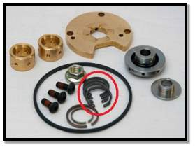
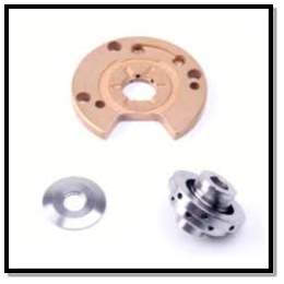
Figure 12 Thrust Collar and Washer [1]
Figure 15 Turbine Wheel with Shaft [6]
Figure 17 Turbine Housing Bolt and Retainer [1]
Figure 19 Damaged Parts due to Lack of Lubrication [9]
Figure 20 Damaged Parts due to Foreign matter and Dirt in the Lubricates [9]
Figure 21 Damaged Parts due to foreign matter in the inlet and exhaust system [9]
Figure 22 Damaged parts due to Over Speeding [10]
Figure 23 Damage due to excessive exhaust temperature [10]
ABSTRACT
With the rising need and expectations to produce more power from an engine different parts called auxiliary parts are developed. Turbocharger is one of the most known auxiliary part. The turbocharger consists of three main subassemblies namely compressor housing, turbine housing and bearing housing. These subassemblies itself has many internal parts which are in continuous motion. As these parts are in motion they are subjected to wear. The turbocharger spins at an extremely high speed, some models approach 160,000 revolutions per minute. The turbocharger relies on oil suspended bearings to allow its shaft to rotate. The speed at which the turbocharger turns, combined with the heat generated by the exhaust system equates to a very sophisticated aspect of tribology to be kept in mind to avoid damages in various parts of the turbocharger. In this project, we would discuss the wear and tear occurring in various parts of the assemblies and find out optimum solution of the same. The different lubricating systems would be discussed to support the solution to the maintenance of the turbocharger.
OBJECTIVE OF THE REPORT
The objective of this report are as follows: –
- Understand the assemblies of Turbocharger which are in motion.
- Identify the tribological problems in the Turbocharger which are inevitable for inspection and maintenance.
- Identify key areas of failure due to tribological wear.
- Propose multiple solutions to the problems identified.
- Get complete overview of the tribological analysis of Turbocharger.
1. INTRODUCTION
A Turbocharger is an auxiliary part of an engine. It works as a centrifugal compressor (driven by exhaust gas) that provide engine to suck higher amount of air than it normally does thus more power can be produced than the normal working of the engine. In most cases, power increases of 50-75% will be achieved with turbo charging.
Generally, the exhaust gas produced during the combustion is expelled out of the engine into the atmosphere. This wasted exhaust gas can be used as an energy source to drive the turbine wheel before being returned to the exhaust system. This is done by means of the Turbo-Charger. The turbine wheel has a shaft at the other end of which is mounted a compressor wheel. Thus, one end of Turbo charger has a turbine wheel while the other end has a compressor wheel. As the turbine wheel is rotated by means of exhaust gases so does the compressor wheel. The compressor wheel draws in fresh air from the air filter assembly, then compresses it to provide a force-fed charge of air for engine to utilize in combustion. The turbocharger spins at an extremely high speed, some models approach 170,000 revolutions per minute to provide enough air flow to feed an engine [1].
The turbocharger has three main assemblies ie. compressor unit, turbine unit and bearing unit.
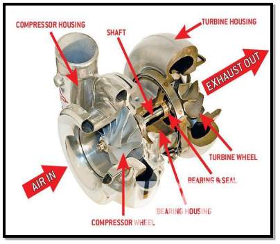
Figure 1 Sectional View of Turbo Charger [2]
2. EXPLODED VIEW OF TURBOCHARGER
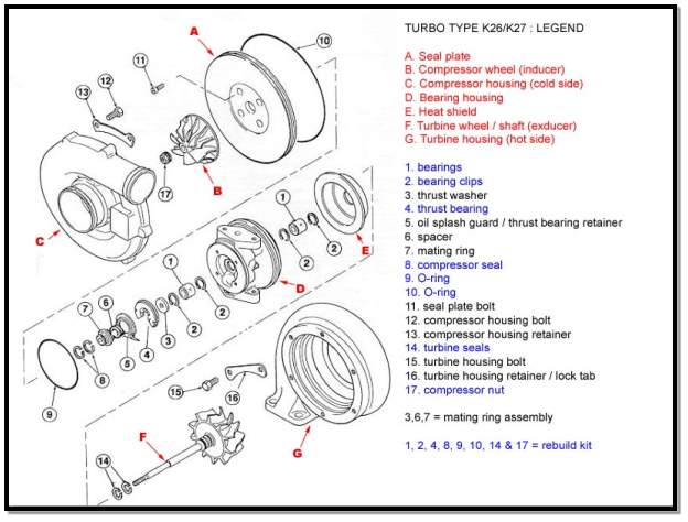
Figure 2 Exploded View of Turbo-Charger [3]
3. KEY AREAS OF TRIBOLOGICAL FAILURES
The main three sub-assemblies of Turbocharger are as follows: –
- Compressor Unit
- Turbine Unit
- Bearing Unit
3.1 Compressor Unit
Compressor unit consists of following parts: –
- Compressor Wheel
- Compressor Housing
- Seal Plate
- Compressor Housing Bolt and Retainer
- Compressor Nut
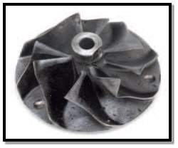
Compressor Wheel: – The compressor wheel is in the compressor housing. It is made of aluminium, cast or forged milled billet. The compressor wheel is used to pull air from the air-filter assembly. It increases the pressure of pulled air by centrifuging it in the compressor volute and then feed the pressurized air to the engine.
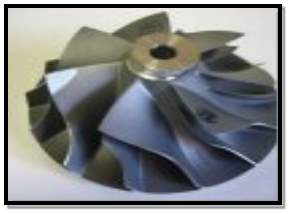
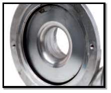
Compressor Housing: – The housing is basically made up of Aluminium. It contains the volute that will guide the air from the air filter assembly to the compressor wheel where the low-pressure air gets converted into high pressure by centrifuging. The High-pressure air generated is sent to the combustion chamber of the engine.
Figure 4 Compressor Housing [1]
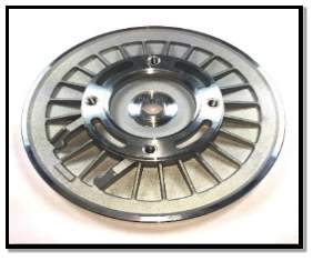
Seal Plate: – The Seal Plate connects the compressor housing with the bearing housing and performs many other functions too. Apart from being the intermediate part, this plate also works as a sealing part providing the sealing for the compressor side. It is works as a diffuser for compressor volute and compressor wheel extruder.
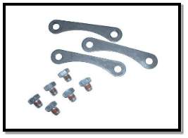 Compressor Housing Bolt and Retainer: – These are the fixings on the compressor housing. These keeps the housing covers tight so that there’s no leakage of the intake air.
Figure 6 Compressor Housing Bolt and Retainers [1]
Compressor Nut: – Retains the compressor wheel and thrust collar to the turbine shaft.
These all parts forms one sub assembly namely Compressor Unit. The various interfaces of this sub assembly are as follows: –
3.1.1 Compressor Wheel and Compressor Nut Interface: –
Compressor Wheel is placed at one end of the Turbine wheel shaft and is fixed with the compressor housing with a Compressor Nut. The interface behaves like nut and bolt. The nut should be tightened because if it is loose, it may cause vibrations and noise. Lose fitting of the compressor wheel results into its colliding with the Housing because these parts are fit in size.
3.1.1.1 Tribological Problem: –
- Abrasive Wear – If there is loose contact between the nut and compressor wheel, the compressor wheel will slide on the housing resulting into abrasive wear of the compressor wheel.
- Thread breaking.
- Fatigue wear – Fatigue wear occurs when there is a contact between asperities with very high local stresses and which is repeated in nature for large number of times during the sliding or rolling motion. The friction force produces alternating compression and tensile stresses, which causes the fatigue wear. There is a relative motion between the internal threads of the body and the external threads of the screw. Though, the gap is negligible but still due to some vibration of the whole machinery the surfaces of both the components will have certain amount of sliding which creates the fatigue loading.
- Jamming of metal flakes.
- Corrosion.
- Friction due to continues rotation of the compressor wheel.
3.1.1.2 Tribological Solution: –
- The nut should be kept tightened so that the alignment is proper and thus abrasive wear can be reduced.
- Don’t overload the screw, as sometimes due to the higher friction torque there might be chance of damage to the surface of threads.
- The nut should be made of galvanized thread.
- Proper selection of material to avoid Corrosion.
- Coating can be applied to avoid direct contact of the surface with the atmosphere.
- Regular Inspection of the Nut.
3.1.2 Compressor Housing and Compressor housing bolts and retainer Interface: –
Compressor housing case is joined using bolts and retainers. If these bolts and retainers are not tight the housing will have gap and there will be leakage of air which will degrade the efficiency of turbo charger. More over dust and other foreign materials come inside the casing and can damage the compressor wheel.
3.1.2.1 Tribological Problem: –
- Corrosion – The housing bolts and retainers are exposed to oxygen and moisture of atmosphere. These can result into rusting of the bolts and retainers.
- If the bolts are not tightened properly then there might be leakage of air which lowers the efficiency of the turbo charger.
- Incoming of foreign elements can damage the compressor wheel.
- Dust can enter in the assembly resulting into severe damage.
3.1.2.2 Tribological Solution: –
- The bolts should be kept tightened and inspected periodically.
- Washer or spacing should be used to avoid friction on the surface of bolt head and retainers.
- Coating should be applied to avoid reaction of oxygen with the surface of material.
3.1.3 Compressor Housing and Compressor wheel Interface: –
There’s a clearance between the compressor wheel and housing. But if the compressor wheel gets misaligned or loose, it will get slides with the housing resulting in adhesive wear.
3.1.3.1 Tribological Problem
- Misalignment of the wheel due to over speeding or lack of lubrication
- Foreign matter in degraded lubrication can result into the filling the clearance which results into wear.
- Loosing of the compressor wheel can result into sliding wear.
3.1.3.2 Tribological Solution: –
- Proper lubrication and approved speed should be maintained to avoid misalignment of the wheel.
- Approved graded lubrication should be used.
- All the parts must be properly tightened.
3.2 Bearing Unit
Bearing unit consists of following parts: –
- Bearing Housing
- Bearing (Journal Bearing)
- Bearing Clips
- Thrust Washer
- Thrust Bearing
- Spacer
- Mating Ring
- Compressor Seal (Compressor Piston Ring)
- Turbine Seal (Turbine Piston Ring)
- O-ring
Bearing Housing: – It is basically made up of cast iron. The bearing housing is the casing consisting of the bearings. It provides the oiling circuits for journal bearings and thrust bearing. In some cases, the cooling of the turbochargers is aided by the water cooling passages.
Journal Bearing: – Journal bearings are usually bronze bushing. They are used to keep the turbine shaft radially inside the bearing housing. These full floating hydro dynamic bearings depends on oil film to provide operation at high speeds.
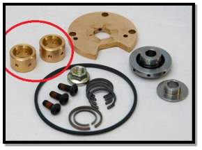
Figure 9 Journal Bearing [1]
 Bearing Clips: – Locates the journal bearings in their proper location within the bearing housing.
Figure 10 Bearing Clips [1]
Thrust Bearing: – In turbocharger bearing housing, thrust bearing plays a crucial role. It is the main part that supports the axial movements of the shaft. Every movement axial, or “in and out” movement must be kept in tight tolerance to maintain the exact clearance needed between the compressor and turbine wheel to housing relationship. Thrust bearings can be made of bronze alloy, sintered iron or steel alloys depending on application.
 All thrust bearing designs utilize hydro-dynamic action with oil as the medium to eliminate friction and allow precision location at high speeds.
Figure 11 Thrust Bearing [4]
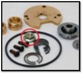
Thrust Collar and Thrust Washer: – The job of the thrust collar is to provide a locating surface between the sides of the thrust bearing. The thrust collar also provides the compressor side seal ring or carbon seal a location point. The collar fits around the thrust bearing usually within .0025” of nominal clearance.
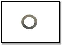
 Thrust washers differ from standard washers or spacers because they must carry a bearing load and not wear out over time. To perform, thrust washers must be heat treated and then polished to achieve a hardness and surface finish that is equal to the bearing that is being supported.
Figure 12 Thrust Collar and Washer [1]
Turbine Seal (Turbine Piston Ring): – The turbine piston ring is a circular spring steel alloy that is used to provide a dynamic seal between the turbine wheel and bearing housing. This seal relies on the turbine wheel design to keep oil away from the turbine housing as well as exhaust gases from entering the bearing housing assembly.
Compressor Seal (Compressor Piston Ring): – The compressor side piston ring is a circular spring steel ring that is used to provide a dynamic seal between the back plate and thrust collar. This seal relies on the design of the thrust collar and proper clearances to provide both oil control as well as keeping contaminates from entering the bearing system from the compressor side of the turbocharger.
O- ring: – A simple sealing ring located between the back plate and bearing housing
These all parts for another sub assembly namely Bearing Unit. The various interfaces in this sub assembly are as follows: –
3.2.1 Turbine Wheel shaft, Journal Bearing and bearing clips Interface: –
Journal bearing with bearing clips are mounted on the turbine wheel shaft. The bearing provides the smooth rotation of the shaft at high speed. The clips are attached with the bearing to fixing the bearings on the shaft [5]
3.2.1.1 Tribological Problem
- Normal Fatigue Failure – Generally alluded to as spalling-is the crack of the running surfaces and consequent evacuation of little, discrete particles of material. Spalling can happen on the internal ring, external ring, or balls. It will dependably be joined by a stamped increment in vibration, demonstrating an irregularity.
- Fretting Corrosion- Most of the time bearing are loose fitted with the shaft or housing so, when there is a relative movement between a bearing’s inner race and shaft fretting corrosion occurs. In this the small particles appear on the outer surface of the shaft and the inner surface of the bearing. These small particles gets oxidized quickly when they get open to atmosphere, hence powder type abrasive material can be found after disassembly of bearing.
- Lubricant failure – This type of Failure is caused by restricted or insufficient lubricant flow or degradation of lubricant’s properties due to excessive temperatures.
- Contamination – It is one of the leading causes of bearing failure. Contaminants include airborne dust, dirt or any abrasive substance that finds its way into the bearing. Principal source is foreign matter in lubricants or cleaning solutions.
- Loose or Tight fits of bearing can cause misalignment resulting into vibrations, wear and noise.
3.2.1.2 Tribological Solution
- The remedy is to replace the bearing before its effect becomes severe or consider redesigning to use a bearing having a greater calculated fatigue life.
- Adequate lubrication can reduce the temperature.
- Quality (in terms of grade) and Quantity of the lubricate should be used. It also maintains the temperature and increased the life of bearing.
- The lubricate used should be free from foreign matter.
- The fits of the bearing on the shaft should be proper. Clips should be used for proper alignment of the bearing.
3.2.2 Turbine Wheel Shaft, Compressor seal, Turbine seal Interface: –
Compressor seal and turbine seal are mounted on the groves of the turbine wheel shaft. These seal (metallic rings) are used for dynamic sealing of bearing unit with compressor and turbine unit.
3.2.2.1 Tribological problem
- Contaminated oil can corrode the seal.
- Over speeding can result into breakdown or crack of the seals.
3.2.2.2 Tribological Solution
- Replacement of the cracked or damaged seals must be done to avoid the oil leakages into the turbine housing or compressor housing.
- Seals of non-corrosive materials should be used or coatings can be provided on the seals.
3.2.3 Turbine Wheel shaft, Thrust Bearing, Washer and Retainer Interface: –
The Thrust bearings are mounted on the turbine wheel shaft to withstand the axial loading and provide the other parts to rotate easily. The retainers are used to fix the movement of the thrust bearing [5].
3.2.3.1 Tribological problem
- Contamination – It is one of the leading causes of bearing failure. Contaminants include airborne dust, dirt or any abrasive substance that finds its way into the bearing. Principal source is foreign matter in lubricants or cleaning solutions.
- Lubricant failure – Failures are typically caused by restricted lubricant flow or excessive temperatures that degrade the lubricant’s properties.
- Normal Fatigue Failure – Usually referred to as spalling-is the fracture of the running surfaces and subsequent removal of small, discrete particles of material. Spalling can occur on the inner ring, outer ring, or balls. It will always be accompanied by a marked increase in vibration, indicating an abnormality
- Over heating – Symptoms are discoloration of the rings, balls, and cages from gold to blue. Temperatures more than 400°F can anneal the ring and ball materials. The resulting loss in hardness reduces the bearing capacity causing early failure. In extreme cases, balls and rings will deform. The temperature rise can also degrade or destroy lubricant.
- Loose or Tight fits of bearing can cause misalignment resulting into vibrations, wear and noise.
3.2.3.2 Tribological Solution
- The lubricate used should be free from foreign matter.
- Quality (in terms of grade) and Quantity of the lubricate should be used. It also maintains the temperature and increased the life of bearing.
- The remedy is to replace the bearing before its effect becomes severe or consider redesigning to use a bearing having a greater calculated fatigue life.
- Adequate lubrication can reduce the temperature.
- The fits of the bearing on the shaft should be proper. Clips should be used for proper alignment of the bearing.
3.3 Turbine Unit
Turbine unit consists of following parts: –
- Turbine Wheel with Shaft
- Turbine Housing
- Turbine Housing Bolt and Retainer
- Heat Shield
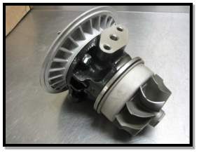
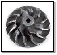
Turbine Wheel: – The turbine wheel and shaft assembly transfers the exhaust energy radially to the compressor wheel. Turbine wheels are usually made of Inconel or other high temperature alloys to allow them to perform in a temperature environment that regularly exceeds 1500℉. The turbine wheel also holds the turbine side piston ring, provides the bearing surface for the journal bearings to ride and also has the quill that holds the thrust collar, compressor wheel and shaft nut.
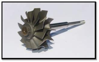
Figure 15 Turbine Wheel with Shaft [6]
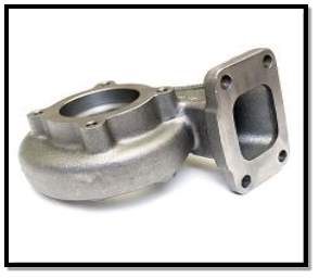 Turbine Housing: – The job of the turbine housing is to collect the exhaust gases and direct them through a volute to the turbine wheel inducer. This increases the velocity of the exhaust gas and provides the drive energy for the turbine wheel rotation. The turbine housing will usually be made of cast iron, or other high temperature alloys. Some turbine housings will have the waste-gate valve built in to the housing.
Figure 16 Turbine Housing [7]
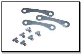 Turbine Housing Bolt and Retainer: – These are the fixings on the Turbine housing. These keeps the housing covers tight so that there’s no leakage of the intake air or no entry of foreign objects.
Figure 17 Turbine Housing Bolt and Retainer [1]
Heat Shield: – Protects the back of the bearing housing as well as the turbine side piton ring seal from direct heat generated by the flow of exhaust through the exhaust housing.

These all parts forms one sub assembly. The various interfaces of this sub assembly are as follows: –
3.3.1 Turbine Housing and Turbine housing bolts and retainer Interface: –
Turbine housing case is joined using bolts and retainers. If these bolts and retainers are not tight the housing will have gap and there will be leakage of air which will degrade the efficiency of turbo charger. More over dust and other foreign materials come inside the casing and can damage the Turbine wheel.
3.3.1.1 Tribological Problem: –
- Corrosion
- Leakage of air lowering efficiency of the turbo charger
- Incoming of foreign elements can damage the compressor wheel.
- Dust can enter in the assembly resulting into severe damage.
3.3.1.2 Tribological Solution: –
- The bolts should be kept tightened and inspected periodically.
- Washer or spacing should be used to avoid friction on the surface of bolt head and retainers.
- Coating should be applied to avoid reaction of oxygen with the surface of material.
3.3.2 Turbine Wheel with shaft and Heat Shield Interface: –
The heat shield is the intermediate part of bearing housing and turbine housing and is mounted on the turbine wheel shaft at one of its ends which is used to dissipate the heat generated in the turbine unit.
3.3.2.1 Tribological Problem: –
- Since the shaft is continuously rotating at high speed if there is some misalignment then the shaft will have direct contact with the heat shield causing friction and wear.
- The heat shield is the intermediate part of bearing unit and turbine unit it must be attached properly otherwise there may be leakage reducing the efficiency of the turbo-charger.
3.3.2.2 Tribological Solution: –
- There should be proper alignment to avoid friction and wear of the parts.
- Appropriate seals should be used to prevent the leakages.
3.3.3 Turbine Housing and Turbine wheel Interface: –
There’s a clearance between the turbine wheel and housing. But if the turbine wheel gets misaligned or loose, it will get slides with the housing resulting in adhesive wear.
3.1.3.1 Tribological Problem
- Misalignment of the wheel due to over speeding or lack of lubrication
- Foreign matter in degraded lubrication can result into the filling the clearance which results into wear.
- Loosing of the turbine wheel can result into sliding wear.
3.1.3.2 Tribological Solution: –
- Proper lubrication and approved speed should be maintained to avoid misalignment of the wheel.
- Approved graded lubrication should be used.
- All the parts must be properly tightened.
4. MAJOR CAUSES, EFFECTS AND REMEDIES/PREVENTIONS OF TRIBOLOGICAL FAILURE
To maintain good service life and performance of a turbo charger, regular basis maintenance practices should be observed along with inspection. Examining lots of failure cases of turbo-charger we concluded that the main reasons of turbocharger failure are lack of oiling, foreign objects entering the turbocharger, etc.
There are many and varied causes for turbocharger failures. They can be grouped into five major categories [8]:
1. Lack of lubrication and/or oil lag.
2. Foreign material or dirt in the lubricating system.
3. Foreign material in either the exhaust or air induction systems.
4. Over-speeding.
5. Damage due to excessive exhaust temperature.
4.1 Lack of lubrication: –
One of the most common reason for failure of turbo charger is inadequate lubrication. If sufficient oil is not supplied to the turbocharger, then the parts of the turbo charger will get damage due to friction as the turbo charger runs at very high speeds. [9]
4.1.1 Effects
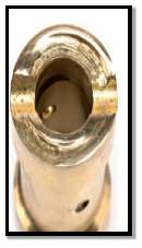
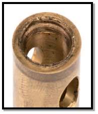
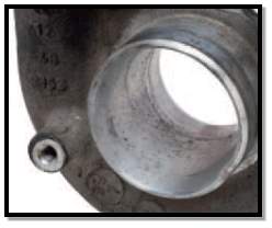
- The bearings can be damaged due to lack of lubrication and thus the connected compressor and turbine wheel can hit the turbocharger housing (Fig. a) and gets damaged. This damage can result into wear marks on the housing (Fig. b).
(Fig. a) (Fig b)
- Inadequate lubrication causes friction. Thus, the rotating parts of the turbocharger cannot attain maximum speed and results into low boost pressure generation in the turbo charger. This low boost pressure cannot perform the engine properly.
- The exhaust system emits black smoke. These are the effects of the engine not being supplied with enough air and a correspondingly too rich fuel-air mixture.
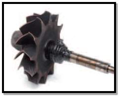
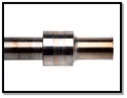
- As shown in (Fig c), we can clearly see discoloration on the shank of the shaft, which arises from friction and high temperatures occurring between the shaft and the bearings. The cause of this is inadequate lubrication. Moreover, the material of the bearing will get deposited on the shaft (Fig d) if the temperature due to friction exceed a certain level.
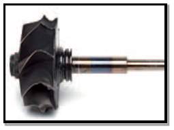
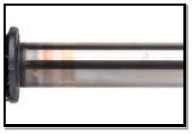
(Fig. c) (Fig. d)
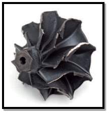
- If the turbocharger is operated without enough oil for a long time, the shank of the shaft can be broken (Fig e). The shaft material can thus burn out and break.
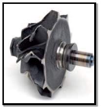
(Fig. e) (Fig. f) (Fig. g)
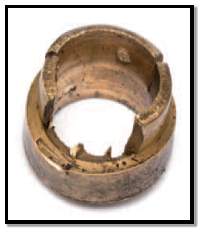
- If bushings that are permanently incorporated in the bearing housing become fused to the shaft, the bushings might turn out of position in the bearing housing (Fig. f).
- The shaft might suddenly become blocked in the bearing housing due to the mixed friction. If the rotating assembly is suddenly blocked, the locking nut of the impeller can become loose.
- The rotating assembly can exhibit a large imbalance owing to the contact with the housing, which might result in the radial bearing breaking (Fig. g).
- The bearing housing can become carbonized due to incorrect oil or heat soak.
- Fretting of the Radial Bearing.
- Carbon Deposits as well as fretting marks are seen on axial bearings.
- Knocked-out bearings can cause too great a wobble of the shaft, whereby the bearing collar might also be damaged.
4.1.2 Causes
- The oil level in the engine is generally too low. Thus, not only the engine but also the turbocharger receives an inadequate oil lubrication and oil cooling.
- An insufficient temperature-resistant lubricating oil results into choking. This leads to increased carbonization. This might cause problems: the oil supply line of the turbocharger and the oil bores in the bearing housing of the turbocharger can become carbonized.
- Turning off the engine during hot condition results into the carbonization of the supply line which means the turbocharger is supplied with inadequate oil.
- If the cold engine was brought to high speeds immediately after the start, there is a risk that the oil supply in the turbocharger is not yet sufficient and hence the oil film in the turbocharger tears off.
- If foreign substances make it in the oil circuit, such as dirt or sealing residues, the oil supply line of the turbocharger and/or the bearing housing of the turbocharger might be clogged.
- If the viscosity of the oil is too high, the oil transport to the bearing points is delayed, which means that the timely oil supply of the turbocharger is not ensured. At too low a viscosity, the carrying capacity of the oil is too low, which can lead to mixed friction.
- If the engine is operated with biodiesel or vegetable oil, there is a risk of the engine oil gelling. This increases the viscosity of the oil and it can no longer be transported through the thin oil bores in the turbocharger.
- The cross section of the bearing housing supply bore might be reduced either through an incorrect flange seal or by a liquid sealant.
4.1.3 Remedy/prevention
- The engine must be allowed to cool down after running at full load.
- Sufficient supply of the oil to the engine.
- Specified engine oils should be used.
- One should undergo regular maintenance as recommended by the manufacturer.
- The damaged component should be replaced by new one of high-quality and specified by the manufacturer.
- The service intervals should be halved if we are operating the engine with biodiesel or vegetable oil.
4.2. Foreign material or dirt in the lubricating system: –
Various particles like dirt, metal abrasion, soot, combustion residue, water, can contaminate the oil. Because of extremely high speed of the turbo charger, even the smallest particles in the oil can cause serious damage to the turbocharger [9].
4.2.1 Effects
- Grooves are formed (Fig a) in the bushings by the smallest foreign substances in the oil. The piston rings in the turbocharger can undergo serious wear due to foreign substances in the oil. These worn piston rings, can no longer adequately seal the turbocharger as a result the oil enters the turbine side, which can be discerned by increased oil consumption.
(Fig. a) (Fig. b)
- The bearing play of the rotating assembly increases due to the worn bushings. This leads to wobbling movements and causes the turbine wheel or impeller to come into contact with the housing and gets damaged (Fig. b). The shaft might subsequently break off.
- The bearing collar, i.e. the thrust washer of the axial bearing, exhibits grooves.
- Grooves or fretting marks are visible in the axial bearing.
- Due to a blocked oil return line, the oil in the turbocharger can no longer flow off and is instead forced out to the compressor and turbine side. On the turbine side, the oil might then burn onto the shaft and coke (Fig. c). Owing to the oil carbon layer, the bearing housing and the piston rings might be significantly worn off consequently.
- The shaft of the turbocharger shows clear signs of wear at the bearing points (Fig. d).
(Fig. c) (Fig. d)
4.2.2 Causes
- If the maintenance intervals are exceeded, the oil filter can no longer filter enough dirt out of the oil. In this case, the dirt particles penetrate through the open bypass valve of the oil filter into the engine circuit.
- If the engine is operated with a blocked oil filter, the small abrasive particles cannot be filtered out of the oil.
- If the cylinder head gasket or the oil cooler is leaking, water will enter the oil circuit and dilute the oil. Its carrying capacity is thus reduced.
- If the engine was repaired, but not properly cleaned before assembly, dirt will be in the engine even before putting it into operation for the first time.
- The charge air cooler was not replaced. Accumulated engine oil, chippings, or fragments from the prior damage usually find their way into the engine with a time delay.
- If the engine is subject to considerable wear, the mostly metallic wear debris also finds its way into the turbocharger via the oil circuit.
- If combustion faults occur in the engine, non-combusted fuel can end up in the oil. The carrying capacity of the oil is reduced by this dilution.
4.2.3 Remedy/prevention
- The maintenance intervals as per the manufacturer’s recommendations should always be complied with.
- Only high-quality oil filters specified for the respective vehicle should be installed.
- Only engine oils specified by the vehicle or engine manufacturer may be used.
- A new charge air cooler and air filter should always be installed when replacing the turbocharger. In addition, an oil change including oil filter replacement must be carried out.
- The air filter housing and charge air line should be cleaned by suction.
4.3 Foreign material in either the exhaust or air induction systems: –
The various parts of the turbo charger fail or damages if foreign substances, like dust, parts of piston rings and valves, sand, screws and sediments gets entered in the intake or exhaust side. These foreign materials has adverse effect and results into failure of the turbocharger as the Turbocharger runs at very high speed. [9].
4.3.1 Effects
- Foreign substances like dust or sand or particles produced during previous damage from the engine or the exhaust manifold can damage the edges of the turbine wheel.
- There is a significant power loss because of damaged and bent air guide plates of the variable turbine geometry (Fig. a).
- Intake air containing foreign substance can damage the impeller (Fig. b). As a result, the vanes and blades might be worn out completely. In addition to this the intake passage of compressor housing might get damaged. (Fig. c).
- The foreign particles get frozen due to condensation in the intake section and can damage the impeller (Fig. d).
(Fig. a) (Fig. b)
(Fig. c) (Fig. d)
4.3.2 Causes
- If parts, for example, fractured piston rings or torn valve, through exhaust manifold come in contact with guiding vanes of the VTG (variable turbine geometry) unit and the turbine wheel.
- If there is a leakage in the intake section or if the air filter is contaminated or defective there can be penetration of foreign substances in the intake section.
- Condensation results into ice formation in the intake section during winter.
4.3.3 Remedy/prevention
- There should be no leakage in the intake section.
- After working on the intake section, it must always be ensured that no loose parts or broken parts should remain there.
- Damaged or contaminated air filter must be replaced by the new one specified by the manufacturer. Supply line of air and the air filter housing should be cleaned.
- Only driving short distances should be avoided.
4.4 Over-Speeding: –
The turbocharger is made up of many parts. These installed parts are designed for a specific speed range. If these parts are operated at speed higher than defined speed range, major turbocharger damages can occur [9].
4.4.1 Effects
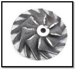
- The material mainly aluminum of the impeller gets deformed permanently as a result of high centrifugal forces produced due to high speeds. Thus, dents are produced at the rear of the impeller (as shown in fig a). These dents begin to grow and increases the outer diameter.
- Vibrations occurs at high speeds. These vibrations can cause impregnation of rotating element with the housing and thus the impeller (rotating element) break apart (Fig. b).
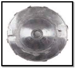
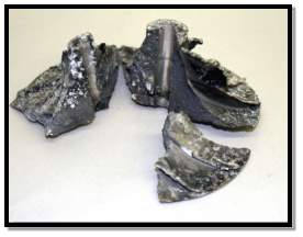
(Fig. a) (Fig. b)
4.4.2 Causes
- Due to tuning of the turbo charger the maximum permissible speed of the turbo charger increases.
- The VTG air guide plates become blocked in the position for low speeds due to carbonization. If the engine speeds are then increased, the turbocharger enters the overspeed range.
- Defective or leakage in any pneumatic or electric control parts.
4.4.3 Remedy/prevention
- The turbocharger must always be left in the original state as supplied.
- The turbocharger may only be installed in the specified vehicles.
- The engine must always be cooled down at moderate speeds after high stress, such as driving at full load.
- Engine oils specified by the manufacturer for specific engine should be used.
- The maintenance should be carried out at regular intervals as per the recommendation of the manufacturer.
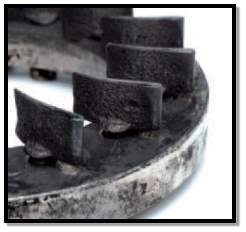
4.5 Damage due to excessive exhaust temperature: –
The exhaust temperature range of every turbo charger is fixed. The turbo charger fails if the exhaust temperature of the turbo charger exceeds the give range.
4.5.1 Effects
- Cracks gets developed in the housings.
- Because of high temperature, when oil containing contaminations is passed through the passages, it gets choked. If the supply line gets choked due to carbonization, then sufficient supply of oil to the turbocharger cannot be achieved. Similarly, if the return line gets coked, the oil can no longer flow off and oil is forced out of the turbocharger.
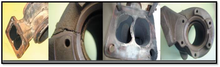
Figure 23 Damage due to excessive exhaust temperature [10]
4.5.2 Causes
- The temperature level has changed due to tuning.
- Inappropriate combustion occurred in the engine.
- Suddenly turning off the engine which is running at full load.
4.5.3 Remedy/prevention
- The engine which is running at full load should be cooled down to moderate speed before turning off.
- The turbocharger should be installed and operated as mentioned by the manufacturer. It should not be modified technically.
- Specific turbocharger works properly with the specified vehicles. So, any type of turbo charger may not be installed in the specified vehicles.
CONCLUSION
From this report, we can conclude that tribology plays an inevitable role in successfully functioning of a Turbo-Charger. All the assemblies of the Turbo-Charger has been discussed briefly with all the possible kinds of tribological problems arising during the maintenance. Different solutions to these problems has been proposed and some recommendations has been proposed in this report in order to prevent a tribological failure. The importance of the tribological analysis has been conceived from this report and has planted a seed of scope for more improvement in the area of maintaining or proper functioning of a Turbo-Charger. Which are the prime locations and the primary failures leading to secondary and tertiary failures if neglected in the assemblies has been discussed in brief. Hence, the significance of a tribological design of a Turbo-Charger has been proposed with a view of preventing a possible catastrophe.
REFERENCES
| [1] | [Online]. Available: http://www.turborepair.com/index.php?option=com_content&view=article&id=129&Itemid=136. |
| [2] | [Online]. Available: http://image.hotrod.com/f/36059684+re0+ar0+st0/hrdp_1205_002how_to_buy_your_first_turbo_.jpg. |
| [3] | [Online]. Available: http://garage.ideola.com/downloads/k26-explode-legend.jpg. |
| [4] | [Online]. Available: http://turbolabofamerica.com/wp-content/uploads/2013/05/brass-garrett-thrustbearing.jpg. |
| [5] | [Online]. Available: http://www.schaeffler.com/remotemedien/media/_shared_media/08_media_library/01_publications/barden/brochure_2/downloads_24/barden_bearing_failures_us_en.pdf. |
| [6] | [Online]. Available: http://s.ecrater.com/stores/23878/5520325937595_23878b.jpg. |
| [7] | [Online]. Available: http://www.banzai-racing.com/store/media/Garrett/ss_size2/HSG-032.jpg. |
| [8] | [Online]. Available: http://www.truckpro.com/Content/Resources/know-your-turbo.pdf. |
| [9] | [Online]. Available: http://www.mahle-aftermarket.com/media/local-media-north-america/pdfs/catalogs-and-literature/turbo-damage-brochure-mo-2-612.pdf. |
| [10] | [Online]. Available: http://miketurboinc.com/pages.php?pageid=29. |
| [11] | [Online]. Available: http://www.musclecardiy.com/performance/turbocharger-failure-analysis-went-wrong-fix/. |
Cite This Work
To export a reference to this article please select a referencing stye below:
Related Services
View all


Related Content
All TagsContent relating to: "Engineering"
Engineering is the application of scientific principles and mathematics to designing and building of structures, such as bridges or buildings, roads, machines etc. and includes a range of specialised fields.
Related Articles

DMCA / Removal Request
If you are the original writer of this dissertation and no longer wish to have your work published on the UKDiss.com website then please: