Sequence of Events and Probable Failure Mechanisms of the World Trade Center
Info: 9239 words (37 pages) Dissertation
Published: 30th Nov 2021
September 11th, 2001 was a day on which everyone remembers their whereabouts when news broke of a plane crashing into the World Trade Center in New York. The author was finishing his lunch break at that time, as the television displayed the World Trade Center (North Tower) in New York with a gaping hole in the shape of an aircraft. The news commentator reported that a small plane had crashed into it, but the author immediately observed that the surface area indicating where the plane crashed was far too wide an opening to be caused by a small aircraft.
Ever since then, the author has researched credible and non-credible theories in the effort to determine how two 110-storey steel-framed buildings collapsed into their own footprint at nearly free-fall speed. This dissertation is focused on what can be proven regarding what happened on that day, with the author’s analysis seeking to determine the probable events that led to the collapse of the buildings. To achieve this, the author calculated the area and mass of the upper section above the impact zone of both towers.
The aim of this dissertation is to ascertain the approximate potential energy stored, and kinetic energy that was released, a force sufficient to crush the lower section, and to conduct a simple impact load experiment. A composite floor design for the beam-framed and truss-framed floor system spanning in each orientation, with loads acting on the floor, is also devised to gain an understanding of the building’s structural materials, loadings and contents.
I would first like to thank my dissertation supervisor Dr. John O’Donnell of the Dublin Institute of Technology, Bolton Street, for the weekly meetings and open-door support, without his input and validation this thesis could not have been successfully conducted.
Secondly, I would also like to show a great amount of appreciation to the department, the wealth of knowledge I have gained from the first sentence of notes to this day and beyond, the role out of the modules over the years has certainly shaped me into thinking more critically and numerically
Finally, I must express my profound gratitude to my partner Michelle, my children and my close family for their love, support and continuous encouragement throughout my years of study and through the process of researching and writing this thesis. This accomplishment would not have been possible without them. Thank you.
1 Literature Review
To understand how a building collapses, we must understand how it was built and the sequence of events that led to its destruction. It must be noted, however, that this topic is extremely sensitive, political and controversial. The topics discussed include the structure’s description, its materials, connections and its design performance. Many factors led to the progressive collapse of the buildings. These include the temperature at which steel loses strength, the effect of the jet’s impact, resulting in localised collapse, with debris acting as a cocoon that increased the temperature further, the structure’s response to the fire loading, the sagging tensile strength overcome by sheer weight of the floor due to heat (thermal expansion), the perimeter and core weakening, buckling, energy generated, the gravitational load and component failures.
The main task of this dissertation is to establish the factors which caused the collapse of the towers, in addition to determining the impact zone, what components failed, the floor’s method of construction, the floor truss, the columns and loading and the detailed connections. The core research for this project will involve the National Institute of Standards Technology (NIST), conducted under the authority of the National Construction Safety Team (NCST) Act, signed into law October 2002. The observations and findings of the final report were released in September 2005. The focus will be on the external and internal tubes/columns, examining their robustness and redundancy whilst paying attention to the floor design and rooftop structure (hat-truss).
The design chapter will include the lightweight composite truss design and composite beam-framed floors used for mechanical rooms and floors above and below them, in addition to the impact of the top section above the impact zone and the kinetic energy it released during initiation of the collapse. The chapter will investigate how it generated further mass and momentum as it progressively collapsed, why the units were collected via the imperial system and converted to the metric system, 1968 Building codes and what regulations were in place at the time of construction (regarding the fire protection of the steel, for example). It will compare these with the regulations of today, along with fire protection relating to steel members, some of which were dislodged by the impact of the plane in New York. Various credible arguments will also be discussed relating to the structure of the towers with the author eventually reaching a conclusion.
2 Structural Components
2.1 Foundation
The site chosen for WTC is adjacent to the Hudson River. Only a few feet down, the soil was completely saturated, so engineers had to find a way to build an underground concrete retaining wall (Figure 2) with a depth of 70ft whilst also preventing the trench from flooding. Draining the Hudson was impractical, so they used a subway construction method known as the slurry trench method: a trench was dug until bedrock was reached, and thick slurry was poured in. As they dug, they piped in a slurry made of water and an expansive clay called bentonite. The bentonite slurry material expanded along the sides of the trench, blocking the groundwater, the slurry which was denser than mud and dirt kept the trench from collapsing. Concrete was poured into each section, then the slurry rose for use in the next section. Approximately 765,000 m3 of soil was removed, then placed into the river. This created the massive soil opening known as the bathtub (Figure 4), to commence construction. To support the massive vertical loads of the columns at the core, grillages (Figure 3) were placed onto concrete footings. Grillages are a stack of horizontal steel girders, packed side by side in several layers. It rests on a thick concrete pad poured on the solid bedrock deep underground. The triangular shape distributes the concentrated weight from the columns over a wide surface area.
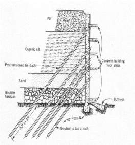
Figure 2: Retaining wall
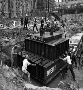
Figure 3: Steel grillage
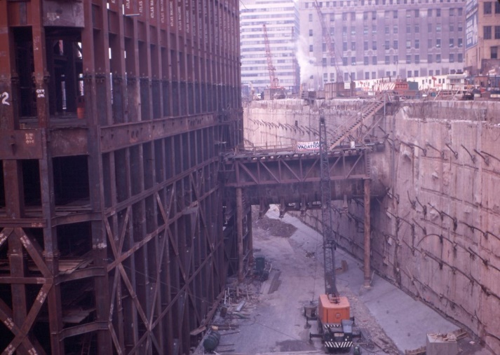
Figure 4: Bathtub
2.2 The Core
To a structural engineer, a skyscraper is modelled as a large cantilever vertical column. Each tower of the WTC was supported by a structural core extending from its foundation to the roof. The towers, and thus the core, were divided into three sections. Separating these sections were the mechanical floors; the size and thickness of the steel core were tapered in each section. The cores were rectangular pillars with numerous large columns and girders, measuring 87 feet by 133 feet. The cores had a separate flooring system, which was structurally independent of the floor diaphragms that spanned between the core and the perimeter walls. The core structures, like the perimeter wall structures, were 100% steel-framed (Figure 5) and supported 70% of the downward force. The core had 47 steel columns rising 110 storeys high. It housed the emergency elevators, stairways and other services, and, to the author’s surprise, was insulated only with gypsum wallboard and spray-on fire-proofing SFRM. It did not have a reinforced concrete wall above the ninth floor.
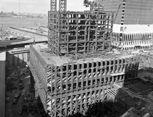
Figure 5: Core
2.3 The Outer Walls
The perimeter walls consisted of dense grids of vertical steel columns and horizontal spandrel plates. The columns were pre-fabricated into three-storey sections. Each square plated column was joined in sets of three (Figure 6) and welded to the spandrels, fitted in a staggered fashion to support gravitational loads. The perimeter walls stiffened the towers against lateral loads. They carried their own weight, along with approximately 30% of the downward force of the building. They distributed the horizontal force to other columns in the case of structural failure via the vierendeel spandrel plates welded to the columns. They formed 59 columns on each side, with the 60th in the corner (240 in total). The walls carried half of the floor space, while the core carried the other half. The spandrels connected the wall columns and regulated the horizontal force distribution. Like the core, these columns also tapered from the base to the top of the building. NIST describes a variation in thickness of column plates from 102mm at the base to 6mm in the upper storeys; this indicates a ratio of 16 to 1 for structural steel from bottom to top.
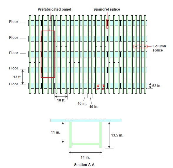
Figure 6: Perimeter wall
Source: NIST, NCSTAR 1 -6C, WTC Investigation (p.7)
2.4 Hat Truss
The hat truss (outrigger truss) (Figure 7) consisted of a set of steel braces. It regulated the wind force, carried the antenna on WTC1 and redistributed downward forces to other columns in the case of local structural failure. In the case of structural failure in the core, the weight of the failing columns would be redistributed via the hat truss to other columns in the core or the walls. The hat trusses were central to the probable collapse sequence described by NIST’s Final Report on the Twin Towers. It determined that the hat truss transferred column instability between the core structures and the perimeter walls.
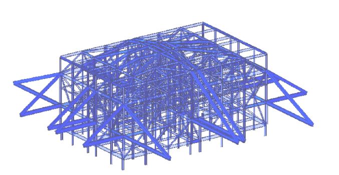
Figure 7: Hat truss
2.5 Floor
Floor trusses were pre-fabricated, composed of steel bar joists, bridging trusses and metal deck; they were optimised so as to be as lightweight (Figure 8) as possible, thus being easily transported, fitted and relatively cheap to assemble. Once the full floor sections were in place a lightweight concrete floor was poured on top, then the steps were repeated for each floor. There were dozens of variations in many floors, which included differences in length for the top and bottom chord size, bearing angles at truss ends, the size of web diagonals and the presence or absence of chord plates. These floors supported gravity loads, provided lateral stability to the perimeter walls (Figure 9) and distributed wind loadings around the building’s frame structure.
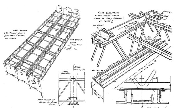
Figure 8: Truss frame: skeleton view
Source: NIST NCSTAR 1-1A, WTC Investigation (p. 106)
The floors of the Twin Towers completed the structural system, whose main elements were the core structures and the perimeter walls. The cores had their own flooring systems, which were structurally independent of the surrounding floor diaphragms. The floor diaphragms consisted of lightweight concrete slabs poured onto corrugated steel pans, which were supported by trusses, providing large expanses of uninterrupted floor space.
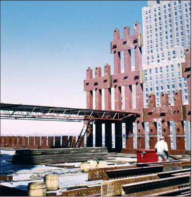
Figure 9: Floor and column connection
Primary double trusses were interwoven with transverse secondary trusses. For the truss-framed floor, steel studs were not included in the floor design for the floor outside the core. Instead, the web diagonal (knuckle) projected above the top chord, which made the floor truss, metal deck and concrete slab act in a composite manner. The bottom chords of the main trusses were connected to the spandrel plates of the exterior wall by viscoelastic dampers (Figure 12). When the tower moved under wind loads, these dampers absorbed energy, reducing the sway and the vibration caused.
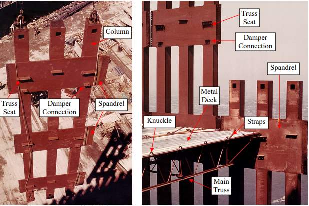
Figure 10: Floor and column detail
Floor types also varied, including mechanical floors that had rolled structural steel shapes. All high strength beam framed floors were grouped into two or three floors throughout the height of the building and carried heavy mechanical equipment, which was strengthened by structural steel frame slabs. They were designed to distribute the equipment weight laterally. Each floor system acted in a composite manner (Figure 11), binding together the concrete and steel materials as a single unit, creating a stronger single supporting unit.
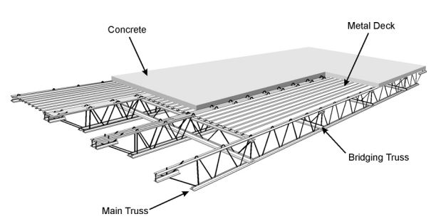
Figure 11: Composite truss-frame floor detail
3 Design Chapter
3.1 Introduction
The purpose of this chapter is to establish the structural integrity of the WTC, an approximate design load NIST NCSTAR 1-1A (p.12) outside the core of the beam framed mechanical floors, and typical truss framed floor ranging above the ninth storey. The materials and floor area were more uniform from the ninth floor; thus, a more accurate calculation can be derived using this as a base point. There were different concrete strength class for beam-framed floors compared to a typical truss-framed floor. For the beam floor normal-weight concrete was used with variance in thickness depending if it’s a mechanical floor, or the floor above or below. For a typical truss-framed floor light-weight concrete was used, with a standard thickness of four inches (101mm), when poured acted compositely with shear studs (knuckle) propagating above the top chord of the truss-frame.
This chapter will also include, the author distinguishing between the construction stage of the floor design against the composite stage using plastic analysis. Establishing the section properties, classification and moment resistance of the beam, also expressing the compressive and tensile resistance of both floor types, determining shear resistance in both, beam and connectors, and locating the plastic neutral axis, in either the beam or slab. Also, an approximation to determine the overall max deflections at each stage, and a simplified approach vibration method to estimate the natural frequency in each orientation.
Determining these results will give a good indication of each floors structural robustness, durability and performance, paying close attention to the truss-framed floor, as the author is assuming it has vulnerabilities due to light-weight components and weak fire-proofing.
3.2 Floor Design
For the vast majority of floors, the area outside the core of a typical floor was supported by a series of approximately, 2ft 5 in. (0.76m) deep floor trusses (National Construction Safety Team Act Reports 2005, NIST NCSTAR – 1-3 p.10). When installed they connected the interior to the exterior onto angled brackets via dampers, with two bolts at each end, then welded for added strength. The floor trusses were 60ft (18.3m) or 35ft (10.7m) in length, fabricated 26ft (8.0m) wide, depending on the relative orientation (Figure 13) and spaced at 6ft 8 in. (2.0m) apart, each floor was separated into three sections, two long one-way spanning areas, two short-way spanning areas and four two-way spanning areas, an analysis of each floor style in both orientations is expressed below.
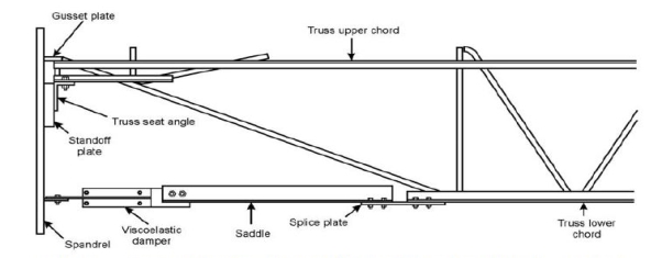
Figure 12: Truss damper detail
3.3 Buildings Dimensions
4 Mass and Potential Energy
4.1 Weight of Steel per Floor
This analysis is based on the upper block above the impact zone, typically the towers were 110 storeys high from ground level, and 70ft subsection below grade. NIST NCSTAR 1-3 (p,16) describes steel components in weight from their manufacturers, this did not include the lightweight floor trusses from Laclede Steel Co, materials listed below are also from the 9th storey and above (Appendix A), as from there the buildings floor structure was more uniform.
Tons kN
Mass of both towers, Mbt 112,800 1,123,941
Mass per tower, Mt 56,400 561,971
Hence, mass per floor Mt / 101 = 559 5564
Rounded, 600 Tons 6000 kN
The actual mass of the upper floors is less than the lower floors due to heavier supporting structures lower in the building. NIST describes a variation in thickness of exterior column welded plates from 4 inches (102mm) at the base to ¼ inch (6mm) in the upper stories, Details relating to the central cores column dimensions were vauge, I’m assuming it was also tapered in the upper section. NIST NCSTAR 1-2B (p. 53) gives a summary of superimposed dead loads (SDL) and live loads (SLL) and floor areas to which they are applied, values are shown in table 1 below. This did not include the structures dead load which NIST describes as construction dead load (CDL) self-weight of the steel trusses, mesh and concrete slab, a separate analysis is taken from NIST 1-1A (p. 11) derived in table 2 and 3 for each floor type (Appendix B)
Table 2: Summary of superimposed dead loads and live loads
| Area (ft2) | Weight (psf) | Load (lbs) | Area (m2) | Weight (kN/m2) | Load (kN) | |
| Core DL | 8,694 | 36.2 | 314,723 | 808 | 1.73 | 1,400 |
| Outer DL | 31,257 | 11.5 | 359,456 | 2,904 | 0.55 | 1,600 |
| Core LL | 8,694 | 19.7 | 171,272 | 808 | 0.943 | 762 |
| Outer LL | 31,257 | 16.2 | 506,363 | 2,904 | 0.776 | 2,254 |
| Total | 1,351,814 | 6,016 |
Table 3: Typical floor, construction dead load
| Area (ft2) | Weight (psf) | Load (lbs) | Area (m2) | Weight (kN/m2) | Load (kN) | |
| Core DL | 8,694 | 50 | 434,700 | 808 | 2.4 | 1,939 |
| Outer DL | 31,257 | 50 | 1,562,850 | 2,904 | 2.4 | 6,970 |
| Total | 1,997,550 | 8,909 |
Table 4: Mechanical floor, construction dead load
| Area (ft2) | Weight (psf) | Load (lbs) | Area (m2) | Weight (kN/m2) | Load (kN) | |
| Core DL | 8,694 | 125 | 1,086,750 | 808 | 5.985 | 4,836 |
| Outer DL | 31,257 | 125 | 3,907,125 | 2,904 | 5.985 | 17,380 |
| Total | 4,993,875 | 22,216 |
Since this data is derived from the 9th floor to the top of the building, the number of typical normal floors are 92 and the number of mechanical floors is 9, thus using the mass from the tables above the following mass per floor can be determined
Typical floors
Mass of normal floors, MT = 6,000 + 6,016 + 8,909 = 20,925 kN
Mechanical floors
Mass of mechanical floors, MM = 6,000 + 6,016 + 22,216 = 34,232 kN
Not much information in relation to the determining the overall mass of the antenna, hat truss and windows in the WTC, the following table of materials are based on approximations
Table 5: Mass of materials
| Weight (kN) | |
| Plane | 1,600 |
| Antenna (WTC1) | 3,560 |
| Hat-Truss | 2,670 |
| Windows | 4,450 |
| Total | 12,280 |
Source: NIST NCSTAR 1 (p.11 & 20), 1-1 (p.12)
Mass above WTC1 impact zone
The plane impacted floors 93 to 99, destroying columns and tearing through the floor trusses, there were 13 typical floors above that zone floors 93 to 106, and 4 mechanical floors, 107 to 110 which will be expressed as follows,
MT13 = 20,925 x 13 = 272,025 kN
MM4 = 34,232 x 4 = 136,928 kN
Total = 306,953 + 12,280 + 6,000 = 427,233 kN
Total mass above impact in WTC1 (rounded) = 430,000 kN
= 43,850,000 kg
Mass above WTC2 impact zone
The plane impacted floors 77 to 85, ripping through a much lower section genrating much larger mass as to WTC1, there were 29 typical floors above that zone floors 77 to 106, and 4 mechanical floors, 107 to 110 which will be expressed as follows,
MT29 = 20,925 x 29 = 606,825kN
MM4 = 34,232 x 4 = 136,928 kN
Total = 743,753 + 12,280 + 6,000 – 3,560 = 758,473 kN
Total mass above impact in WTC2 (rounded) = 760,000 kN
= 77,500,000 kg
5 Experiment
By scaling down over 100,000 times the weight of each damaged section of the towers to grams and by using some household, Appendix C items, a simple yet effective approximation analysis can be derived to separate the difference between a static and dynamic load. The dynamic force is defined by the maximum deflection of the needle on the spring scale A good example of this is, aircraft landing equipment or suppose you bench press, for example, 50kg, put that load at a height of 3.7m and drop it, that same 50kg will crush you. Due to certain limitations of available information and the method of calculation, the values for loadings, mass, potential and kinetic energy are approximations. Factors which may affect the accuracy are listed in Appendix D, along with estimated effects caused by reasonable deviation.
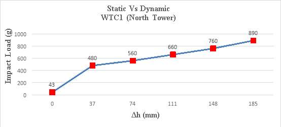
Figure 24: WTC 1 scaled impact load
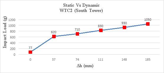
Figure 25: WTC 2 scaled impact load
Thus, using these results with a relatively simple calculation the potential energy and kinetic energy released with the respect of each tower can be derived as follows:
Formulas used from mechanics and materials. James M. Gere (2004) Chp2 (p. 128)
The potential energy (PE) due to gravity (close to earth) of any object can be calculated as
PE = mgh
where,
m = mass of block above zone (kg)
g = gravity (m/s2)
h = height of impact zone (m) h1 = (96 x 3.7) = 355 m
h2 = (79 x 3.7) = 292 m
WTC1
PE1 = 43,850,000 x 9.81 x 355 = 1.5×10¹¹ Joules
= 150,000 MJ
WTC2
PE2 = 77,500,000 x 9.81 x 292 = 2.2×10¹¹ Joules
= 220,000 MJ
This potential energy is suddenly converted into kinetic energy (K) as soon as the columns buckle and snaps, it can be expressed as K = Mv2/2
where,
M = mass of the section above the impact zone,
v = velocity = √2gh = 8.52 m/s
hence
g = 9.81 (m/s2)
h = 12ft (3.7m)
Assuming each floor is intact, its possible (h) is higher around the crash zone due to the immense force of the aircraft crushing several floors and the fire aftermath collapsing the floors before the towers began their gravitational collapse.
Kinetic energy of upper block of each tower
K1 = 43,850,000 x 8.522 / 2 = 1.6×10⁹ Joules
= 1,600 MJ
K2 = 77,500,000 x 8.522 / 2 = 2.8×10⁹ Joules
= 2,800 MJ
According to NIST, “the vertical capacity of the connections supporting an intact floor below the level of collapse was adequate to carry the load of 11 additional floors if the load was applied gradually and 6 additional floors if the load was applied suddenly. Since the number of floors above the approximate floor of collapse initiation exceeded six in each WTC tower (13 floors in WTC 1 and 29 floors in WTC 2), the floors below the level of collapse initiation were unable to resist the suddenly applied gravitational load from the upper floors of the buildings”.
6 Analysis of the Collapse
Understanding the construction of the towers, we can understand their destruction. The towers were structurally innovative, known as a tube-within-a-tube structure. The core housed a grid of massive steel columns (inner tube), and the perimeter walls had dense steel columns (outer tube) so that the tubes carried the weight of the buildings, which was different to standard design at the time, whereby columns took up internal floor space. The WTC was different in that all the columns were shifted to the core and the perimeter; this design created OOS, which maximised tenant space.
To gain an understanding of the building’s redundancy and the immense force of the impact of the planes hitting the towers, the closest example was another, separate attack, in 1985, targeting the Murrah Building in Oklahoma. The Murrah Building (Figure 26) was nine stories tall. At the front of the building, 11 columns supported the upper floors, and the lower two floors were reduced to six supporting columns; tied into that was a transfer girder. A truck loaded with explosives was parked outside the front centre of the building adjacent to six load-bearing columns. It destroyed three of the six columns on the left-hand side of the building. Consequently, the transfer girder had only three supporting columns remaining: one inner and two corner columns on each side, with very little support. Almost immediately, progressive collapse ensued, and half of the building collapsed, with many lives lost, mainly due to the building collapsing.
Figure 26: Murrah building
A similar, yet far more redundant phenomenon was behind the collapse of WTC. Leslie Robertson calculated how well the towers would handle impact from the largest aircraft in service at the time – the Boeing 707, not the Boeing 767, which was established in 1982, nine years after the WTC opened. Both were similar aircrafts, apart from their wingspans, but the design factored in a Boeing 707, The Bridge, Leslie E. Robertson (2002) lost in fog and seeking to land while low on fuel, with a speed of only 180 mph (80m/s).
The energy contained in an airplane or other moving objects is proportional to its velocity. If the velocity is doubled, this results in four times the energy; tripling the velocity leads to eight times the energy, and so on. The exterior of the WTC was robust, and it did absorb the impact of the aircraft, but perhaps not all aspects of a crash (i.e. the jet fuel spray, explosion, gypsum wallboard and fire) were considered by the design team, perhaps because the probability of such an occurrence was deemed insignificant.
Tall buildings are built with graduated columns. The lower storeys of the WTC had to hold up the weight of 110 floors above, so their box columns were built with welded steel plates which were 100mm thick. Higher up, at the impact zones, the columns only had to hold up 20 or 30 storeys above them, so their box columns had steel plates approximately 8mm thick. At mid-height, the box columns would have had walls 60mm thick. These robust columns would have resisted the impact of the aircraft much more than the lighter columns higher up.
At 13:46 GMT, the hijacked American Airlines Flight 11 struck WTC1 on the north face side almost dead centre of the 96th floor, at approximately 440 mph (200m/s), banking 25 degrees to the left at a descent angle from the horizontal of 10 degrees, damaging floors 93 to 99, in addition to severing 35 perimeter columns out of 60, along with six core columns (Figure 27), heavily damaging three others. Furthermore, computer analysis showed that 43 out of the 47 core columns were stripped of their insulation.
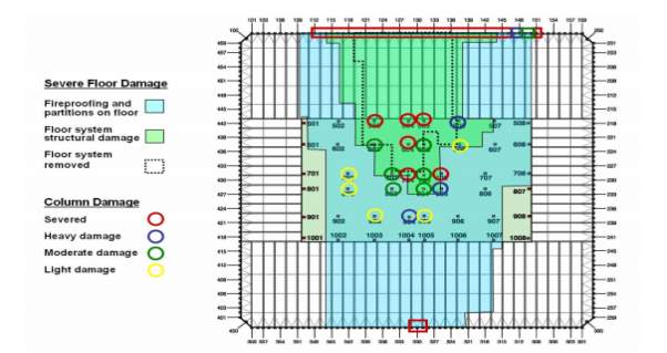
Figure 27: WTC 1 column and floor damage
At 14:03 GMT, the hijacked United Airlines Flight 175 crashed into WTC2; the impact damage was even more catastrophic. The plane was travelling at a speed of 540 mph (240m/s), banking 35 degrees to the left with a descent angle of six degrees downward, striking the south face of the tower slightly to the right of the building, damaging floors 77 to 85, severing 33 external columns (Figure 28), 10 core columns and heavily damaging another. Thirty-nine of the 47 core columns were stripped of their insulation. Insulation was also stripped from the trusses throughout the damaged floors. The planes hit the towers with much more force than that for which they were designed. However, the towers were able to cope with such an impact, and they remained standing, allowing some people to evacuate.
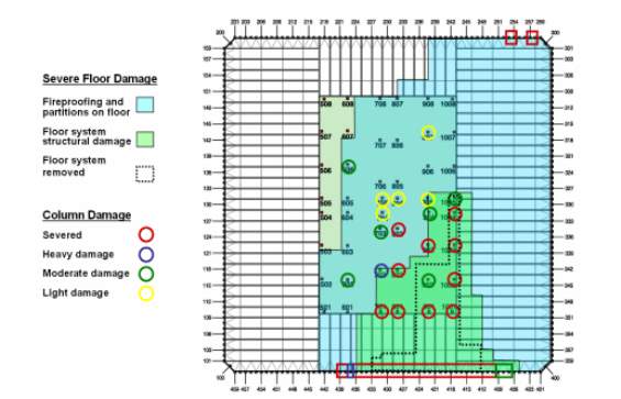
Figure 28: WTC 2 column and floor damage
6.1 The Structure’s Response to Fire
After breaching the building’s perimeter columns and penetrating much of the inner core and floor area, approximately 10,000-15,000 gallons of jet fuel sprayed across several floors, igniting multiple high-intensity fires which pushed out debris, acting as a furnace generating more heat transfer. Apart from the catastrophic structural damage to the WTC, the force from the impact severed the sprinkler system, thus compromising the supply of water from the storage tanks. SRFM located on the floor trusses was blown off. It is difficult to estimate how much fireproofing was dislodged, but photographs and other evidence of the aftermath point to very little fireproofing being left on the steel. Depending on the alloy involved, steel melts at approximately 1,500oC. It loses approximately 50% of its strength at 550oC, while the fires in the towers were predicted to have reached approximately 800 to 900oC.
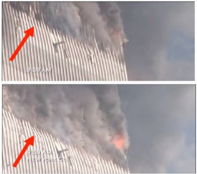
Figure 29: Buckling columns
As a result, the damaged floor area and trusses heated up and gradually lost their strength. With very little or no protection, they began to expand and sag, and as they sank, they pulled on the outer wall by as much as 150cm in places. Bowing continued until the outer columns finally reached breaking point. The building can clearly be seen giving way due to the immense structural damage sustained at the initial impact zone (Figure 29). The columns snapped simultaneously, and the buildings collapsed, with initiation taking place on the weakest side (Figure 30). The impact mass of the upper section (760,000 kN) for WTC2 weighed more than one and half times that of the Titanic, according to Felkins, Leigh and Jankovic (1998), impacting from a height of 3.7m at a velocity of 8.52m/s.
Under normal conditions, fires in high-rise buildings usually start in a specific area, and they are contained using either sprinklers or other fire safety measures. This was not the case in this exceptional circumstance. The 1968 New York Building Code required testing to establish the fire rating of steel material and thickness specification required to give steel a fire rating. It meant that those with bare steel did not have a fire rating anymore. The designers of the floor trusses, Laclede Steel Co, Leslie Robertson and Yomi Yasuaki, recognised the need for such endurance testing of the composite floor system. NIST claims that the “Port Authority confirmed, there is no evidence that fire resistance tests of the WTC floor system were ever conducted”; the fireproofing was the only component in the building that was not tested. One must ask: how could a building of this magnitude and this stature in the world receive such a short test in fire protection? They designed in depth for lateral wind loading and possible aircraft impact, but why did they not go into such depth when testing for fire? Was aircraft fuel and the aftermath factored into the design? Was the fireproofing consistent in all areas of the buildings?
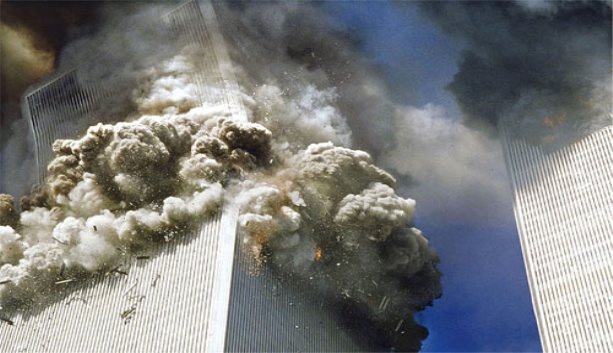
Figure 30: Initial collapse, WTC 2
7 Arguments
No shortage of commentary and conspiracy theory existed following the September 11th attacks on the World Trade Center. The bottom line of the official post-mortem on the WTC, according to NIST, is that crucial SFRM (Figure 31) was assumed to have been removed from the steel girders by the impacts of the aircraft, allowing heat to cause subsequent infernos, weakening the structure to the point of eventual collapse. On immediate inspection, this would seem to be a reasonable hypothesis from what is visible in the countless video footage available. However, an unusually relative number of professional architects, engineers and physicists, Architects and Engineers for 911 Truth (AE911Truth) and people across all walks of life have challenged this verdict.
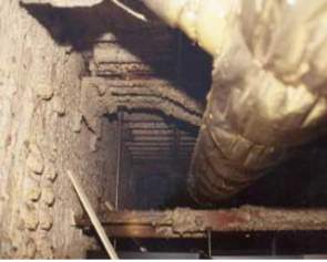
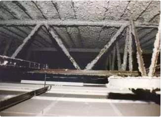
Figure 31: Exposed steel: mid-span and connection
The main assertion of AE911Truth is that the fire and damage were not enough to allow for complete structural failure brought on by the event. They argue that never had such a large building collapsed with such a devastating loss of life due to fire. However, this is a complete misconception. Likewise, who could have credibly predicted the scenario of a direct impact from two aircraft and the ensuing petroleum-fuelled fire? The purpose of this chapter is not to discredit or smear anybody; it is to explain what the author personally found to be the most compelling arguments.
7.1 Jet Fuel Melting Steel and Molten Metal
NIST demonstrated using shotgun testing that portions of the weak bond-strength SFRM became dislodged, resulting in bare steel exposure. The main reason for this assumption is from the steel wreckage collected post-collapse. There was very little left on the material, and it is difficult to predict a timeframe for dislodgement without knowing the exact thickness or which areas the SFRM were blown off, but certainly, under these conditions, it is possible, especially if it was not upgraded or partially dislodged over the lifetime of the structure, due to building maintenance, or elevator shaft momentum.
Jet fuel does not need to melt steel to lose strength; as the temperature increased, the heat transferred from the fires was sufficient to weaken the steel to the point of structural failure. Minutes before the collapse of WTC2, molten steel was seen pouring down the channel rails. AE911Truth and Dr. Thomas W. Eagar, a professor of materials engineering at the Massachusetts Institute of Technology (MIT), and his graduate research student, Christopher Musso, determined the maximum temperature of a building fire to be 1000°C, which is not even close to the melting point of steel (approximately 1500°C). They noted that “the observed black smoke emanating from the Twin Towers was consistent with a typical oxygen-starved building fire. Eagar and Musso (2001) concluded that the actual temperature most likely remained below 650°C”.
Planes have crashed and caught fire in open areas, with black smoke seen emanating from them as in the case of the fuel leakage experienced by a China Airlines flight (Figure 32) in Naha, Japan, Sturcke, J (2007) Plane Explodes at Japanese Airport. The Guardian, 20th August. The most important factor in the colour of smoke from fires is the fire content, and there was an abundance of content on each 4,000m2 floor, along with the contents and materials of the plane.
AE911Truth also claims that Nano-thermite was used to initiate the collapse of WTC. Numerous videos display bright red molten metal flowing out of WTC2 just before the collapse. Depending on the alloy involved, aluminium has a melting point of approximately 660oC. According to the temperature chart, aluminium glows bright red from 650oC to 900oC. Since the aircraft was composed of 80% aluminium and the WTC perimeter walls were covered in aluminium coating, it is highly possible that this is what is seen pouring out of WTC2 before it collapsed. In addition, it fell out on the side where the plane was most likely to have pushed the debris, so if the fires were as hot as this research indicates, this rise in temperature is more than sufficient to melt aluminium.
7.2 Controlled Demolition
The construction method of the WTC involved purely steel-framed buildings. Most high-rise buildings today have a reinforced concrete inner core or concrete-enclosed outer columns or both, yet the WTC had neither. Instead, WTC steel columns and trusses were protected, by weak-bond SFRM that varied in thickness and gypsum wallboard, which is very good in fire conditions. However, it is brittle upon impact. In 2001, the complete collapse of a tall steel building due to fire was unprecedented; however, in January 2017, a steel-frame high-rise in Tehran, India, the Plasco Building, caught fire, and it collapsed to the ground. In 2005, Windsor Tower in Madrid, which was framed in both steel and concrete, caught fire and partially collapsed. The upper steel portions completely collapsed, leaving only the building’s concrete core and massive concrete sections, called transfer floors. The WTC did not have these concrete structures, and the Tehran and Madrid fires prove that fire can destroy steel constructions.
When London’s Grenfell Tower experienced a long and intense fire in 2017, it gave conspiracy believers a new talking point. Grenfell Tower was a concrete building, not steel or even a combination of both. The construction is critically important to a building’s performance in a long fire, so this comparison is completely misleading. In long fires, steel weakens considerably. It also expands, and if expansion is prolonged and uneven connections can break, then failure will occur. This is why steel buildings incorporate fire protection insulation on their members to delay these dangerous conditions.
To demolish a building with a controlled demolition, charges are placed within the primary load bearings of the structure, and collapse is initiated from the bottom up, not the top down, video evidence displays from numerous angles how collapse was initiated from the impact floors and progressed from the initiating floors downwards. AE911Truth also claims that squibs can be seen ejecting laterally from the towers and claims this as proof that explosives were used. Again, this is simply science, and is quite a laughable assumption. Here, we have a group of top professionals in their field of practice failing to factor in the giving conditions, the release of colossal kinetic energy over the massive open area of the floors and the huge volumes of air they stored.
Another claim is that the top section could not possibly crush the lower section. Physics teacher David Chandler, as cited by AE911Truth (2008), argues that, Newtons third law, for every action, there is an equal and opposite reaction, the impact force of the upper section on the lower section was only a third of the upper part’s weight. However, the present author has found that his estimate of the downward impact force was too low by a factor of thirty-four for WTC1 and twenty-five for WTC2. In addition, Chandler measured the rate of collapse in his analysis, but this cannot be measured in dust-obscured videos. There is a non-explosive building demolition technique used in France called the Verinage technique, whereby a hydraulic rig pushes against the load bearing walls until they fail, then the upper section is used to crush the lower section, in a manner very similar to how the towers collapsed.
If two identical cars are travelling at the same speed and crash into each other, they will both absorb energy from each other, and the impact should look almost symmetrical. If one car is stationary and the other is travelling towards it at a speed of 8.52 m/s (31 km/h), however, the stationary car would be forced out of the way, and the faster the speed, the harder it impacts, because of the increase in force. The “truth movement” might have some credible arguments, but it cannot be right; otherwise, it would have generated more support by now.
8 Conclusion
The calculations in chapter 5 determined that the upper block in WTC1 weighed a total of 430,000 kN, and WTC2 upper section was 760,000 kN. The potential energy stored of the top section in WTC1 was approximated to be 150,000 MJ, thus WTC2 potential energy was 220,000 MJ once released it exerted a large kinetic energy impact force per floor of 1,600 MJ (WTC1) and 2,800 MJ (WTC2) onto the lower block. Using the scaled version for example of the load via both graphs, it demonstrated large forces exceeding the design loads from 8 (Figure 23) to just over 11 (Figure 24) times the weight as the static load, that is only the first impact from each building. After collapse begun as each floor collapsed it gained more mass and acceleration, creating a domino effect down the building, heavier impacts pulverising the structure below into dust from progressive collapse; thus, there was no way that the columns below could have taken this large overload. Putting this into context, MJ has a more meaningful energy unit, TNT equivalent, which expresses how much of this is needed to detonate to reach the same amount of energy, hence 150,000 MJ, when converted, equals 36 ton of TNT, that’s for WTC1, for WTC2, 220,000 MJ converts to 53 tons of TNT, that’s over twice as much TNT, Ana Swanson, Washington Post (2015), used for the Hiroshima atomic bomb in the case of WTC1 and over three times that for WTC2, just from the buildings structure and contents collapsing from such a massive height.
When you raise a mass against gravity at the height of the WTC, this requires energy. That energy becomes stored as gravitational potential energy. If that mass falls down, that energy is then released as energy in motion, or kinetic energy. When the WTC towers were built in the early 70s, fuel needed to be burned to hoist the construction materials into place; the higher a column was lifted, the more potential energy it was given. All of this energy was held in the building for decades. In the aftermath of the impacts in both towers, there was practically two multi-story buildings weighing down on an already weakened structure below. With the uncontrolled fires raging throughout the building and several floors severed from the impact, the core, the floors and the perimeter walls were weakening; thus, the collapse of the WTC was inevitable.
The vast majority of high-rise buildings have redundancy design factored into their calculations to allow for the loss of one or more primary structural members, such as a column. However, when the redundancy is exceeded or the members that are taking the extra load weaken, multiple members will fail, and the shifting loads eventually overstress the adjacent members. The perimeter tube design of the WTC was highly redundant; it survived the loss of many exterior columns and extensive damage to the core due to aircraft impact, but the ensuing fire led to other steel failures. The building’s redundancy measures could no longer support the gravitational load above. At this moment, the entire upper section of each tower fell the height of one floor, or maybe more, initiating a progressive, and utterly catastrophic, collapse of each of the structures: a once-static load transformed into a massive impact load pulverising each floor.
Much of the potential energy was converted into kinetic energy. The weight of the debris steadily increased beyond the support capacity of those floors, and they collapsed sequentially. At the same time, local collapse of the floors caused the heat-weakened columns to lose their lateral support, which caused them to buckle and collapse under the intense weight of the floors above.
Since WTC1 was struck almost in the central part of the north face of the building, the centre of the inner core was highly damaged. Video evidence shows the large antenna at the top giving way first, just before the collapse ensued. This would suggest that the core failed first; it is likewise for WTC2 except that it was hit on the south face, slightly east to the centre of the building. Numerous videos displaying its collapse clearly show the perimeter columns buckling inward, suggesting the floor trusses and their connections were intact. The buckling was initially plastic, but it quickly led to fracture at the plastic hinges. This excessive deformation far exceeded the column’s yield strength, snapping the members, with the top section slightly tilting over on the already weakened side as the collapse initiated. The towers then collapsed in what was almost free-fall speed the buildings did not fall at actual free-fall speed, because the dislodged debris that fell off beside it had no source of resistance except gravity, because the debris was falling at free-fall speed and the building was not. The cause was the dynamic reaction of the upper block and the extended heating of the steel columns and floors to a sufficiently high temperature for the steel to lose its yield strength.
The potential energy that was in the building for decades after the WTC was built was stored in the upper section. The higher the building, the more potential energy it is capable of generating. The top section had acquired colossal kinetic energy and considerable downward velocity. The vertical impact and weight of the upper section on the lower section applied an excessive vertical dynamic load on the structure below, far exceeding its load capacity, even if it was not heated. The part of the building lying beneath was then impacted again and again by an even larger mass falling with a greater velocity, and the series of impacts and failures then proceeded all the way down.
As the large mass of the collapsing floors above accelerated and impacted on the floors below, it caused an immediate progressive series of floor failures, punching each one as the acceleration sequence progressed. This left very tall, free-standing portions of the core and perimeter columns acting in a spaghetti-like manner. As the unsupported height of them increased, they became slender; with no connections, they peeled outward and fell at a faster rate than the building itself, indicating that the towers did have some resistance after all.
The basic philosophy of structural building codes is to ensure high redundancy within the structure, to prevent ductile failure of the members and to provide public safety and sufficient time to evacuate the building. Under this philosophy, members that are overloaded will deform elastically within the elastic range of the material and will show an increase in large deformation and deflections. The design allows for such measures; if these specifications were not in place, many more lives would have been lost that day. It is evident that the collapse of the towers was natural and fully consistent with the laws of physics regarding buildings of this magnitude.
The author believes that the building’s tube-within-a-tube steel construction design, tapered box columns, non-reinforced concrete core, lightweight floors and connections, SFRM thickness and bond strength certainly did not cause the collapse. However, they played a role in assisting it secondary to the impact. The mechanical floors, although strong, could neither arrest the vertical collapse of the WTC towers nor reduce the collapse velocity. They were not designed for that purpose. The calculations in chapter four show that when the crush font reached these floors, the accumulated kinetic energy was already much higher than the energy required to crush these frames. The towers simply had too much force above the impact for the structure to stay standing once the impact load initiated. The author firmly believes that, under no circumstances were there any other malicious factors involved in their destruction. The buildings were well-designed and performed extremely redundant given the unprecedented circumstances. If they had been designed poorly, they would have collapsed once the aircrafts struck. It was the unfortunate chain of events that followed the impact of the aircraft, and the floors that were severed by them.
There are endless areas for further evaluations on the WTC, such as bolted connections. Appendix E labels the truss floor detail NIST NCSTAR, WTC Investigation 1-1A (p.98), while Appendices F and G display a 2D Linpro model of each orientated composite truss-framed floor, which can be used for determining the horizontal or vertical loading used to calculate bolted connections, although this method is a slight approximation, because it excludes several components, (e.g. perpendicular bridging truss, welded stiffeners and dampers). Perhaps in future, the author could analyse this in more detail with more recent software to facilitate a more accurate analysis.
9 Recommendations
Since 2001 building design and codes have been updated extensively, the WTC was a unique design of its generation, maximising floor space with supporting columns pushed out to the exterior panels. Many recommendations were proposed by NIST following their final report, but to put all these into practice for future building design costs would be extremely high, it simply would not be practical. The probability of a fire getting out of control in a high-rise building is very low, however as we have seen with certain events, the consequences and loss of innocent life is far greater, below are some effective recommendations.
Fireproof testing, bond strength, thickness and quality control
Fireproofing should be improved by enhancing the bond strength of the material, an example of this would be to mix concrete or other cohesion/adhesion mixtures so the bond strength is greater than the density. Consistent documented quality control inspections and regular testing should be carried out over time periods to analysis product durability, fire rating and strength.
Increased structural robustness, concrete encased core stairways and columns
Reinforced concrete encased columns and protected core, harden enclosure to house the stairways and elevator shafts, core columns have sufficient redundant paths, to avoid vulnerabilities core column design should overcompensate for abnormal eccentric and axial loadings. Lateral steel bracing with diagonal members, with stronger more robust beam/truss to column connections.
Extra load and fire redundancy measures, fire aftermath
Design for uncontrolled fire flow, backup water supply tanks can be used if one is compromised, segregated floors (outrigger floors) specifically over-designed in the event of any circumstance to house people in the event of evacuation and in the event of full or partial collapse, impact load would not penetrate beyond said floors, the technology of today can monitor loads on large floor areas to analysis their structural performance under behavioural loads.
Cite This Work
To export a reference to this article please select a referencing stye below:
Related Services
View all


Related Content
All TagsContent relating to: "Engineering"
Engineering is the application of scientific principles and mathematics to designing and building of structures, such as bridges or buildings, roads, machines etc. and includes a range of specialised fields.
Related Articles

DMCA / Removal Request
If you are the original writer of this dissertation and no longer wish to have your work published on the UKDiss.com website then please: