Dissertation on Capacitive Deionisation for Water Desalination
Info: 6961 words (28 pages) Dissertation
Published: 16th Nov 2021
Tagged: Chemistry
Controlled electrochemical doping of graphene-based 3D nanoarchitectures electrodes for supercapacitors and capacitive deionisation.
Abstract
Chemically-doped graphenes are promising electrode materials for energy storage and electrosorption applications. Here, an affordable electrochemical green process is introduced to dope graphene with nitrogen. The process is based on reversing the polarity of two identical graphene oxide (GO) electrodes in molten KCl-LiCl-Li3N. During the cathodic step, the oxygen functional groups on the GO surface are removed through direct electro-deoxidation reactions or reaction with the deposited lithium. On the anodic step, nitrogen is adsorbed onto the surface of graphene and subsequently reacts to form nitrogen-doped graphene. The doping process is controllable, and graphene with up to 7.4 at% nitrogen can be produced. The electrochemically-treated electrodes show specific capacitance of 320 F g-1 in KOH aqueous electrolyte and maintain 96% of this value after 10000 cycles. The electrodes also display excellent electrosorption performance in capacitive deionisation deceives with the salts removal efficiency reaches up to 18.6 mg g-1.
Introduction
Capacitive deionisation (CDI) is an emerging water treatment technology that uses ion adsorption in the electrochemical double layer to achieve desalination.[1] CDI requires no heating or high pressure and operates at low voltage, giving it promising economic advantageous over other conventional desalination technology such as reverse osmosis, thermal distillation, and multistage flash distillation.[1-3] Also, CDI requires little infrastructure, and can be used for treating water with low and moderate salt concentrations, which make the process scalable and suitable for many rural and less-developed areas.[4, 5] Since the salts ions are removed and stored in porous lightweight electrodes, CDI offers a portable desalination technology that can be adapted for small devices.[4] Other advantages of CDI include: low water wastage, small space to operate, and retention of adequate minerals required for the body.
CDI shares the same principles of operation as supercapacitors; therefore, most of the materials, if not all, that have been employed as electrodes for CDI were first tested for energy storage devices. Carbon materials are always in the forefront of ECDL device electrode materials due to the high conductivity, low cost, high surface area and ability to tune the structure to obtain new properties and better performance.[6] Many carbon-based materials have been investigated, such as activated carbon, carbon aerogel, carbon nanotubes, mesoporous carbon and carbon fibres.[7] With the emergence of graphene at the beginning of this millennium, several attempts have been made to use it as an electrode material for CDI and supercapacitors.[8-11] However, due to the restacking of graphene flakes by van der Waal forces, the ion-accessible surface area of the graphene electrode is much lower than the theoretical value.
To circumvent this problem, different approaches have been suggested to minimise the aggregation of graphene sheets. For example, mixing with nano-spacers such as nanofibres, carbon nanotubes, fullerenes, and nanoparticles has been applied to prevent restacking.[12, 13] Also, the production of crumbled and aggregated graphene, where the restacking is prevented by the rough morphology induced on the graphene surface, has also been investigated.[14, 15] Although these electrode-manufacturing approaches solved the problem of pore-distribution, they were found lacking in their symmetric adsorption and desorption of counter-ions, electrochemical stability, and in many cases increasing the interior resistance of the electrode. Additionally, they suffer from relatively complicated manufacturing processes and high production costs.
In parallel with the efforts to increase the specific surface area, there is another trend aiming to increase the specific capacitance and the ion adsorption efficiency in both supercapacitors and CDI by anchoring a source of pseudocapacitance on the surface of graphene. Decorating graphene with metal oxides such as MnO2, SnO2, and ZnO has been reported to increase the specific capacitance.[8, 16, 17] TiO2 nanoparticles, for example, can enhance the surface wettability due to their hydrophobicity properties and consequently improve the performance of ECDL devices.[8] However, the mechanical stability of graphene/metal oxide composites as CDI electrodes is always questionable.
Nitrogen-doped graphene may represent a more mechanically stable alternative due to the strong bond between N and C.[18] N-graphene can be obtained in two different ways: (i) direct synthesis in the presence of carbon and nitrogen sources such as chemical vapour deposition (CVD),[19] segregation growth and arc-discharge;[20, 21] and (ii) post-preparation treatment where graphene is treated in the presence of a nitrogen source in processes such as hydrothermal treatment, thermal annealing, and plasma treatment.[18, 22] Both synthesis approaches use corrosive or toxic precursors, a sensitive processing atmosphere, and complex setups, or suffer from low productivity. Besides, it is hard to effectively control the doping or maintain highly porous structures of the electrode.
The present work aims to design a 3D porous structure of nitrogen-doped graphene with a highly specific surface area through an easy, simple and affordable electrochemical technique. In one single step, a sponge-templated GO was activated and doped with nitrogen in a controlled manner, which allowed the nitrogen content and pore distribution to be determined. In addition, quenching the high temperature molten salts allowed the formation of a wavy surface that creates nanochannels between the graphene flakes and therefore improved the ion accessibility to the active surface. The 3D nanoarchitectures exhibits excellent electrosorption performance when used as a binder-free electrode for a CDI unit. The electrode also showed excellent electrochemical performance as a supercapacitor.
Results and discussion
Electrochemical nitrogen doping of graphene
A simple synthesis approach for producing nitrogen-doped graphene electrodes with a controlled hierarchical pore structure is described schematically in Figure 1. First, GO is electrophoretically deposited on Ni foam from an aqueous suspension. In order to convert GO to nitrogen-doped graphene, two pieces of the GO-coated Ni foam were used as the electrodes in a 2-terminal electrochemical cell with KCl-LiCl-Li3N as the electrolyte. On the cathodically polarised electrode; there are two associated reduction processes that lead to the removal of the oxygen functional groups from the GO surface: (I) direct electro-deoxidation, where the bond between the oxygen groups and carbon breaks under the applied potential similar to reactions 1 and 2, and (II) chemical reduction with Li that deposits on the cathode.[14]
By reversing the polarity of the electrode, the nitride ion oxidises under the anodic current to form adsorbed nitrogen atom according to equation 5.[23] This adsorbed nitrogen atom then reacts with the graphene to form N-doped graphene.[24, 25] The cyclic voltammogram (Figure S1 in the supporting information) of the GO-coated Ni-foil in the electrolyte with Li3N clearly shows an irreversible oxidation wave at around 1 V vs. Li/Li+. Since this potential is too low for the Cl– ion discharge, the only other anion in the system, it is reasonable to refer the oxidation wave to the formation of the adsorbed nitrogen atom according to equation 5.
Cathode: C – OH + e– = C + OH– (1)
Cathode: C – RCOO + e– = C + RCOO– (2)
C – OH + Li= C + LiOH (3)
C – RCOO + Li= C + Li-RCOO (4)
Anode: N3- =Nads+ 3 e– (5)
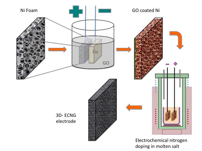
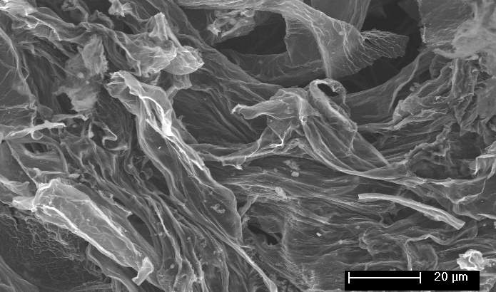
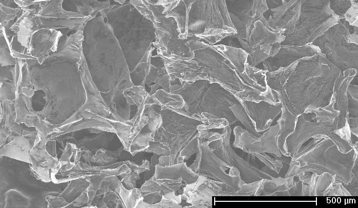
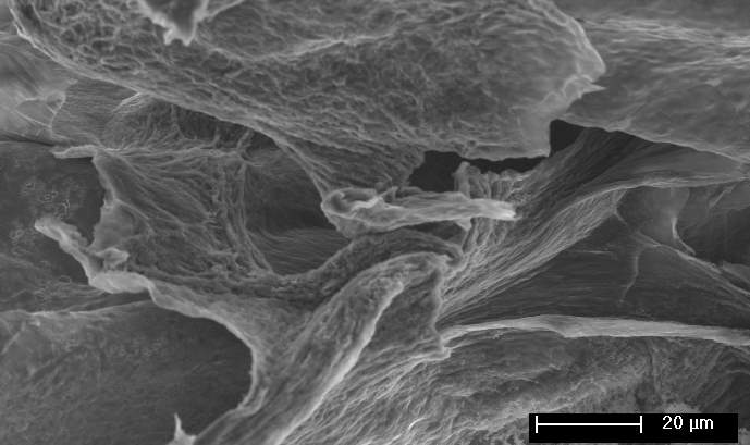
Figure 1: Schematic Illustration for the fabrication of ECNG electrodes, and SEM images of the prepared electrode
To confirm the above-mentioned mechanism for the doping process, the chemical composition and the surface character of the GO after applying electric potential for 3 hours were determined by Fourier transform infrared spectra (FT-IR), and X-ray photoelectron spectroscopy (XPS). FT-IR spectra of the original GO and the electrochemically nitrogen-doped graphene (ECNG) are shown in Figure 2a. The GO spectra shows the typical characteristic peaks of GO: (1) the alkoxy C–O stretching vibration at 1053 cm−1;(2)epoxy C–O stretching vibration at 1220 cm−1; (3) aromatic C=C stretching vibration at 1625 cm−1; (4) C=O stretching vibration at 1746 cm−1; and (5) the O–H stretching and deformation vibrations at 3420 cm−1 and 1395 cm−1 respectively.[26]
After reduction and functionalisation, the stretching vibration of the oxygen functional group weakened significantly confirming their efficient removal. Additional two new peaks appeared at ~1471 and ~1550 cm-1 corresponding to the N-H and is the sp2 C-N starching vibrations;[27] this indicates the introduction of N through the electrochemical nitriding reaction. The C-N peaks were not observed when the process was repeated in a melt free of Li3N. The presence of the peak at 1625 cm−1 corresponding to the aromatic C=C group after functionalisation suggesting that the frame of sp2-bonded carbon atoms was retained well despite the high temperature nature of the process.
The XPS wide scan spectrum also confirmed the doping with nitrogen (Figure 2b). The N1s peak was observed at ~400 eV together with the C1s and O1s peaks at 284.6 eV and 531.8 eV, respectively. Figure 2C shows that N 1s spectrum can be fitted by four distinctive peaks: pyridinic N at 398.4 (N-6), pyridonic or pyrrolic N (N-5) at 399.8, quaternary N (N-Q) at 400.7 and oxidised N (N-X) at 402.5 eV. The typical structures of these N functionalities are illustrated in the supporting information. The low energy peak is pyridinic N in which the N atom substitutes a carbon atom and bonds with only two sp2 carbon atoms at the zigzag boundaries of an atomic vacancy or graphene edge. N-5 represents pyrrolic N in a 5-member heterocyclic ring and supplies the π-system with two p-electrons. The pyridonic N functionalities have a tautomer with hydroxypyridine-like structures. N-Q is graphitic N, which is located inside the graphitic carbon plane and bonds with three sp2 carbon atoms.[28, 29]
It is clear from figure 2C that the N-5 and N-6 are predominant for the ECNG, suggesting that the N-functionalities are concentrated on the edge of the flakes and the highly defective aromatic rings. The nitrogen functionalities located in the middle of graphite (N-Q) are generally found to be less active than other nitrogen functionalities for the application of supercapacitors, which give an advantage to the current functionalisation method.[30] The oxygenated functionality (N-X) is considerably lower, which is a surprising result given the anodic nature of the nitrogen-doping process. However, we believe that the N-X groups have been converted into NOx gases or other N functional groups during the cathodic polarisation and also due to the high temperature nature and the low oxygen partial pressure in the molten salts cell.
In fact, the oxygen content of the sample after the electrochemical treatment is significantly lower than the original GO starting materials. The C1s peaks of the original GO can be deconvoluted into 4 peaks associated with different oxygen functionality: C–O groups (hydroxyl and epoxy, ∼286.5 eV), C=O (carbonyl, ∼288.3 eV) groups, and O–C=O (carboxyl, ∼290.3 eV) groups. The peaks of the oxygen functionality almost disappeared from the spectrum after the electrochemical treatments, with the exception of a hump at the high energy level. It should be mentioned here that the efficient removal of the oxygen functional group is not only limited to the electrochemical treatment, but it also takes place by the thermal reduction.
Also, post electrolysis chemical reactions are involved. The samples were allowed to cool in the molten salts after the electrolysis. We were able to detect a reverse current form the cell suggesting a glovaostatic process is taking place due to the dissolution of the Li. We have observed white deposited of LiOH on the ECNG, which can be attributed to reaction 1.
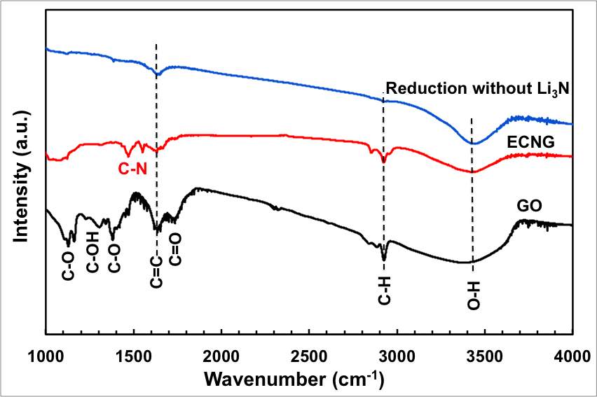
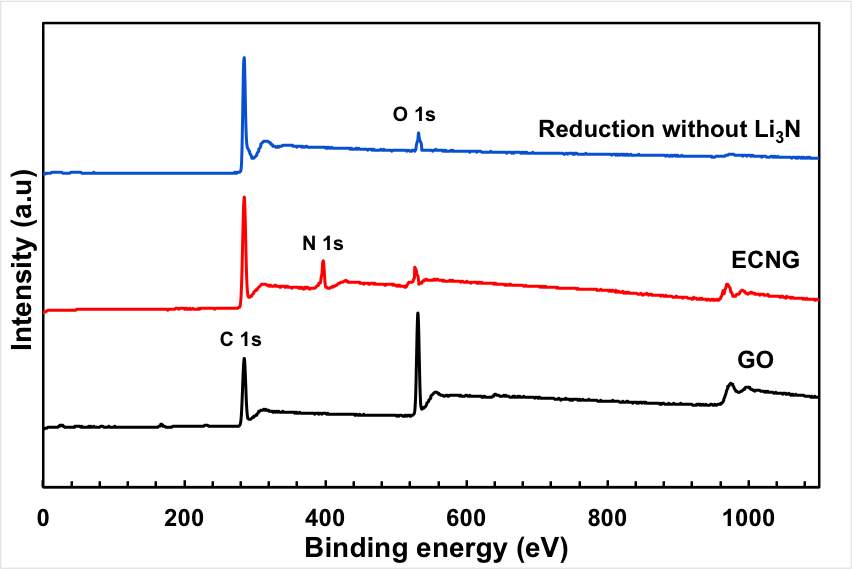
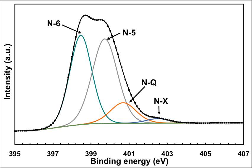
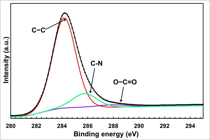
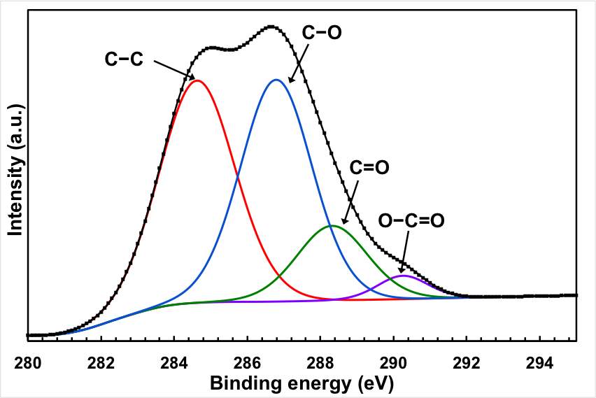
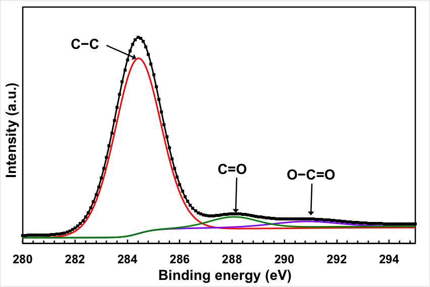
Figure 2: Chemical analysis of the electrochemical reduction and doping process (a) FTIR for the starting GO, doped and undoped graphene, (b) XPS wide scan for the doped and undoped graphene, (c) and (d) XPS N 1s and C 1s spectra of the doped graphene, (e) XPS C1s spectrum of GO, and (f) XPS C 1S spectrum of the undoped graphene.
Interestingly, the amount of nitrogen doping almost doubled every hour of electrolysis. Figure S2 (Supporting information) showed the XPS wide scan of the electrochemically-doped graphene after different electrolysis time. Increasing the applied voltage has a less pronouncing effect. The sample electrolysed at 3.5 V has less nitrogen and less oxygen than that treated at 2.5 V. At high applied voltage, decomposition of the electrolyte is taking place resulting in fast Li deposition on the cathode, and the anodic reaction is predominant by the chloride ions discharge. Indeed, the deoxidation of the GO surface functional groups is improved due to the enhanced Li deposition which drives equation 3 more to the right. On the other hand, the nitrogen adsorption is disturbed by both the chlorine formation and the dissolution of the Li from the cathodic step.
Beside its ability to change the chemical composition, high temperature molten salt processes can change the morphology of the materials due to the simultaneous heat-treatment. Graphene produced or treated using molten salts usually forms a heavily wrinkled morphology if quenched from the liquid state. This is because the non-equilibrium cooling causes the flakes to keep their morphology in the suspension. Also, some of the salts may trap and solidify between the flakes, thus leaving nano-channels when the salt is leached out. The SEM images in Figure 1 showed fluffy and heavily corrugated graphene sheets with numerous wrinkles and folded regions. The Ni foam as the backbone supports this crumpled and porous structure, which significantly improves the mechanical stability of the electrodes.
Testing the electrochemical supercapacitor
Before using the materials for capacitive deionisation, we first tested the ECNG as electrodes for ECDL supercapacitor. The symmetrical device was assembled by sandwiching a filter paper between 15 mm diameter electrodes in a coin cell. We first used cyclic voltammetry to evaluate the performance of the device at different scan rates. Figure 3a presents the CVs of the ECNG supercapacitor with 6 M KOH solution as the electrolyte at different scan rates. All of the CV curves display a nearly rectangular shape between −0.2 and 0.8 V, suggesting pure electric double layer capacitance for all samples. The CV data show that there is a decrease in the specific capacitance with increasing scan rate, which can be attributed to there being insufficient time available for ion diffusion and adsorption inside the voids within the electrode material. The lack of any faradic peaks in the scanned windows suggesting low concentration of the oxygen functional group on the ECNG, which have been reported to have irreversible reactions in this potential window. The graphene flakes seem to completely cover the Ni substrate and effectively prevent it from reacting with the electrolyte, judging by the lack of any sign of a faradic process.
The galvanostatic charge/discharge curves were recorded at different current densities and used to calculate the specific capacitance. Consistent with the CV results, all galvanostatic charge/discharge tests show symmetric features with a fairly linear slope, indicating a nearly ideal supercapacitor. The ECNG electrodes exhibit small IR drops upon discharge, indicating that they are quite electrically conductive. A specific capacitance as high as 320 F g−1 was obtained at a current density of 0.3 A g−1, about 55% more than the undoped electrode. Even without nitrogen doping, the electrochemically anodised sample showed high gravimetric capacitance compared with other reported graphene materials. Table S1 summarises the capacitance obtained from the current work with that in the literature. The anodic activation that led to high surface area and the wrinkled morphology of the flakes that prevented the re-stacking is responsible for the high specific capacitance. We believe that the wrinkled structure of the flakes is a result of the quenching in molten salts.
The ECNG showed higher capacitance than the controlled undoped sample. Although these results are expected and agree with previous work, the origin of this increase remains arguable. Theoretical and experimental studies have suggested that the capacitance enhancement by nitrogen doping is a result of one of the following factors: (1) pseudo-capacitance contribution from reversible or quasi-reversible redox reaction, (2) enhancement of the quantum capacitance due to a change in the Fermi level, and/or (3) boosting the ECDL capacitance by increasing the electrode/electrolyte interaction. The absence of any redox peaks in the basic electrolyte suggested that there is no significant pseudo-capacitance contribution. It is likely that the capacitance improvement for the ECNG electrode is a result of a synergistic effect of the quantum capacitance and ECDL. The strong presence of the N-6 and N-5 functionalities supports this mechanism. The N-6 doping causes carbon vacancies, and the system loses one electron for each carbon atom missing compared to pristine graphene. Therefore, the system is like a p-doping semiconductor, and the density of state close to the Fermi level increases significantly, which consequently increases the quantum capacitance.
It has also been reported that the bending energy between N-6 regions in the graphene basal plan and the K ions from the electrolyte is higher than that between K ions and any other nitrogen functionality.[18] The high binding energy means a large number of ions accommodated on the electrode surface, raising the ECDL capacitance even for the given surface area of an electrode.
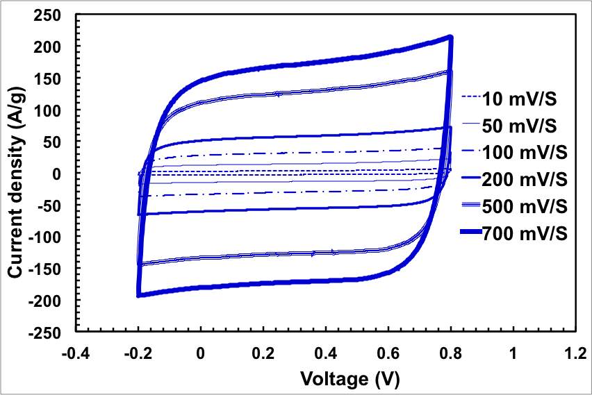
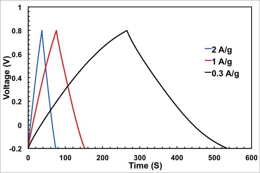
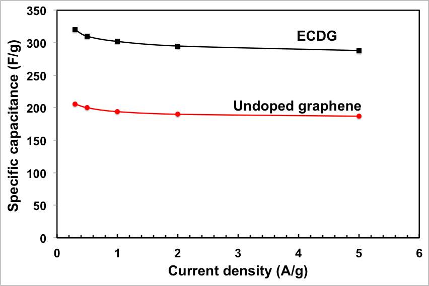
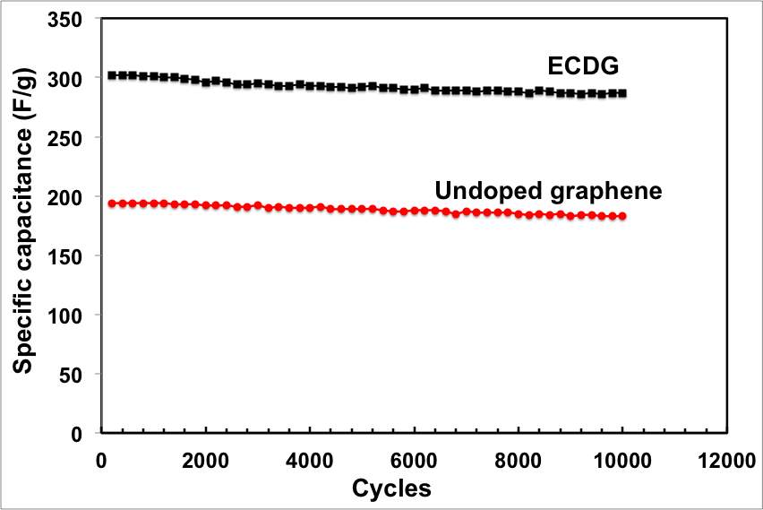
Figure 3: Electrochemical performance of the ECNG electrodes; (a) CV in 6 M KOH at different scan rate, (b) galvanostatic charge/discharge in 6 M KOH at different current density, (e) change of the specific capacitance with current density for both ECNG and undoped graphene, and (d) cyclic stability of the ECNG and the undoped graphene electrodes
Evaluate the performance of the CDI system
Figure 4 shows the changes in the solution conductivity of the sample which was electrochemically treated for 1 hour (ECNG-1) during the adsorption/desorption cycle in a 10 mM NaCl aqueous solution at 1.2V. The initial conductivity decreased rapidly in the first few minutes of applying the potential as a result of the fast electrosorption of the ions on the fresh electrodes with a large number of available surface adsorption sites. The conductivity of the solution then slowly decreased until reaching a plateau, suggesting electrosorption equilibrium because the electrostatic repulsion between the adsorbed ions prevents the constancy of electrosorption. The process was reversible, and the adsorbed ions are released upon reversing the applied potential, also in a fast rate at the initial stage. The recorded current of the CDI cell during the adsorption/desorption cycle shows a similar profile to that of the solution conductivity, indicating that the current is mainly related to the ions captured and released during operation.
It can be concluded from Figure 5a that the descending rate of the conductivity of ECNG is much faster than the undoped electrode, indicating that both Na+ and Cl– ions are prone to be easily adsorbed at ECNG electrode. With an increasing level of nitrogen doping, the conductivity of the solution dropped to lower values at a faster rate, which can be explained by increasing the binding energy between the salty ions and the nitrogen islands on the graphene flakes. Numerically, the specific electrosorptive capacity, expressed as the mass of deionised ionic charge per total mass of the graphene in the electrodes, is calculated at the end of the third electrosorption cycle to be 10.7 and 18.6 mg g-1 for the ECNG and the undoped electrode, respectively. The removal capacity of the nitrogen-doped graphene is higher than any graphene-based electrode reported in the literature and more than 6 times higher than the commercial activated carbon (2.9 mg g -1, ESI†).
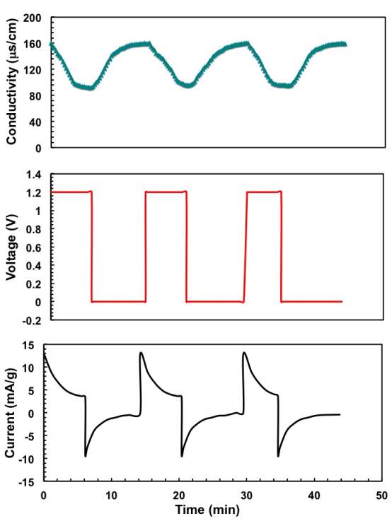
Figure 4: Multiple electrosorption and regeneration cycles at an applied voltage of for the ECNG-1: (a) conductivity, (b) working voltage, and (c) current measurements.
For commercial use of a CDI system, it is important to maximise the salt removal within a short period. Therefore, it is also important to study the CDI kinetic. One quick tool is to estimate the time required to reach equilibrium from the adsorption/desorption curve. By equilibrium, we mean that the ion transport rates become zero and the applied cell voltage is completely built off in the ECDLs in the electrode; also, there are no further changes in the concentration or voltage gradients between the electrodes and the bulk electrolyte.
Figure 4 shows that the conductivity of the NaCl solution reached equilibrium within about 6 minutes for the ECNG electrode. This is much shorter than AC and other reported graphene-based materials. Eventually, the ECNG is faster than the undoped graphene electrode (Figure 5a), because of the improved wettability that has been previously reported for the nitrogen doped graphene and also because of strong attractions between the N-6 nitrogen with Na+ ions.[31] However, it has recently become more common to use the average salt adsorption rate (ASAR) as a characteristic of the CDI cell kinetics. The ASAR expressed as the mass of the salt removed per total mass of the active materials in the electrode during the charging time, is calculated at the end of the third charging cycle to be 0.064 and 0.045 mg g-1 S−1 for the ECNG and undoped graphene electrodes, respectively (Figure 5b). These values show that ECNG outperforms the reported other carbon-based electrodes, including graphene, and is comparable with the hybrid CDI system where Faradic reactions are taking place on one of the electrodes.[32]
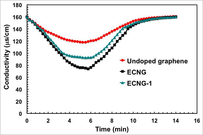
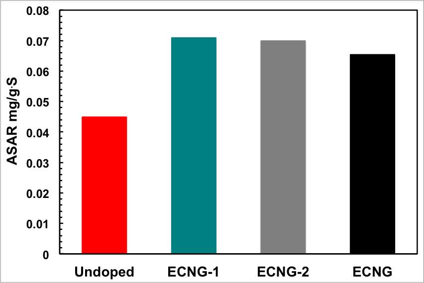
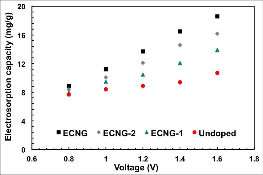
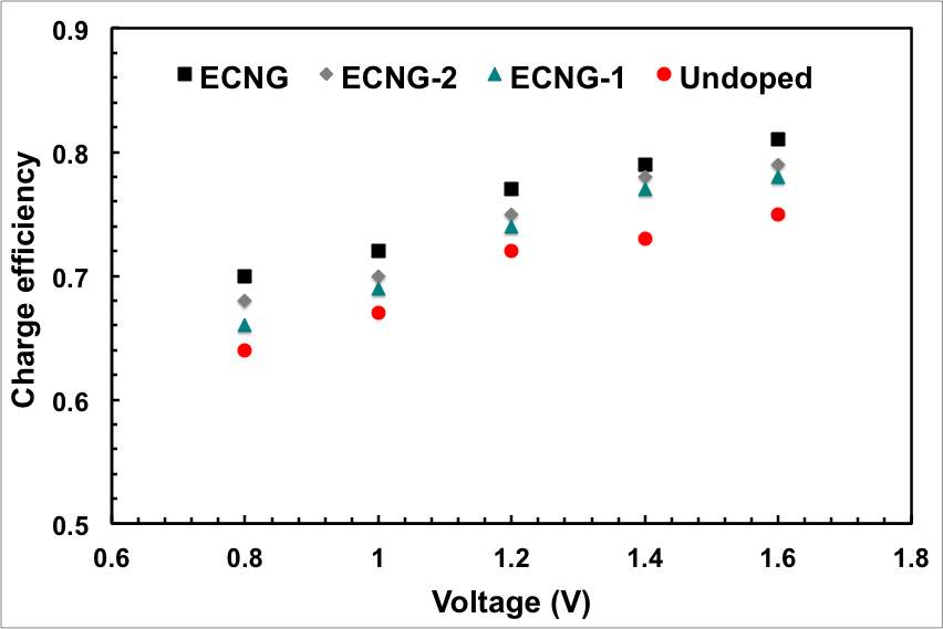
Figure 5: Impact of the level of doping and the CDI cell voltage on the electrosorption performance; (a) conductivity, (b) ASAR, (c) electrosorption capacity, and (d) charge efficiency
We then investigated different factors that control the CDI process. The relation between the solution conductivity and the applied cell potential in the range between 0.8 and 1.6 is represented graphically in Figure 5a. The decline of conductivity and consequently the ion removal efficiency are trivial at potentials below 1 V. At higher potentials, the coulombic interaction increased and the solution conductivity decreased significantly with time as a result of removing the electroactive spices. It should be mentioned here that there were no gas bubbles observed during the process, indicating that no water electrolysis was taking place. This is basically because of the IR drop of the cell, mainly from the electrode binder and electrolyte, consumes part of cell potential. The calculated specific electrosorptive capacity at 1.6 is obviously the highest in the experimental range.
Another important criterion in determining the performance of a CDI system is the charge efficiency, Λ, which is the ratio of adsorbed salt at equilibrium, Γsalt, and charge, ΣF, divided by Faraday’s constant, F. The charge efficiency is important because it defines the ratio between the actual amounts of ions adsorbed on an electrode to the theoretical value that should have been adsorbed from the invested charge. In an ideal situation, where there is no energy lost, the value of Λ is unity, i.e. for each electron transferred, one salt molecule is removed from the electrolyte. However, Λ is less than unity because the adsorption of a counter-ions (the ions that have an opposite charge to that of the electrode) on an electrode is simultaneously associated with desorption of the co-ions (the ions that are expelled from the charged surface) from the same electrode.
This co-ion expulsion from the electrodes is the origin for the reduction of Λ to values below unity. Figure 5d shows the calculated value of Λ at various applied voltage for the samples with different nitrogen content. The charge efficiency reaches a highest value of 0.81 for the sample with highest nitrogen content at 1.6 V. This value is comparable with other carbon-based electrodes (Table S2 in the supporting information). It should be noted that the sequence of materials with increasing charge efficiency exactly matches the sequence for salt adsorption capacity, i.e. with increasing nitrogen doping of the graphene. This is possibly because the nitrogen doping creates negatively charged islands on the surface of graphene that favours the adsorption of the cations on the nitrogen sites and minimises the counter ions/co-ions conjunction.
Experimental section
Materials and Electrodes Peroration
The GO solution was synthesised from natural graphite flake (Alfa Aesar, 325 mesh) by a modified Hummers method, as described elsewhere.[33, 34] For fabricating the porous electrodes, GO flakes were electrophoretically deposited from a 3mg ml-1 solution on a Ni foam that served as the anode. The Ni foam was carefully washed with water, ethanol, and acetone to remove any contamination using an ultrasonic bath.
The electrophoretic deposition was carried out at a constant current of 10 mA for 60 seconds between Ni foam anode and Cu cathode. The GO coated Ni foam was then dried under vacuum for 1 hour at 60oC. The coating, washing and drying steps were repeated for three times until the Ni foam was fully covered with graphene.
The electrochemical nitrogen doping and the electrochemical reduction of the undoped sample were conducted in a molten salt reactor consisting of a vertical tubular Inconel® vessel with 70 mm inside diameter, and 600 mm height placed inside a Vecstar® ceramic-lined 100 mm vertical tube furnace (Figure S5 in the supporting information). Further details about the molten salt electrochemical setup can be obtained elsewhere.[35, 36] All of the electrochemical doping and reduction was conducted under an Ar atmosphere. The electrolyte was a binary eutectic mixture of LiCl-KCl prepared from vacuum dried reagent grade chemicals.
Both doped and undoped electrodes were prepared using two identical pieces of GO-coated Ni foam that served as both the cathode and anode in a two-terminal cell. To prepare the nitrogen-doped electrode, Li3N was added to the electrolyte as a source of nitride ions. The GO-coated Ni foams were connected to a stainless rod, which served as the current collectors and attached to the outer cell via holes drilled in the reactor lid. In a typical synthesis experiment, about 250 g of the electrolyte was charged into a zirconium crucible and placed at the bottom of the Inconel® vessel. The furnace was then heated to 150oC at a rate of 1oC min-1 under a contentious flow of Ar and held at that temperature for 12 hours. The temperature was then ramped to 500oC and held at that temperature for 30 minutes before applying any potential. To remove residual water contamination further, pre-electrolysis was carried at potential difference of 1.5 V, using a platinum wire cathode and a glassy carbon rod anode. When the cathodic current density became less than 0.5 mA cm−2, the pre-electrolysis was terminated.
A potential difference of 2.5 and -2.5 V was swiped between the two electrodes every 60 seconds using Iviumstat Electrochemical Interface. Unless otherwise specified the ECNG was electrochemically treated for 3 hours. The electrodes were then removed from the salts and allowed to cool under argon. After being removed from the furnace, the electrodes were washed with distilled water and ethanol and dried under a vacuum overnight.
Supercapacitor electrochemical performance
The electrochemical performance of the supercapacitor devices was tested in conventional two electrode coin cells using 6 M KOH as the electrolyte. The electrochemical performance of the supercapacitor device was measured by cyclic voltammetry and galvanostatic spectroscopy using an Iviumstat Electrochemical Interface. The specific capacitance was calculated from the CV curve using the following equation, Cs (F g-1) = 4IΔt/ΔEm, where I is the current loaded (A), Δt is the discharge time (s), ΔE is the potential change during the discharge process, and m is the mass of active material (g).
Batch mode CDI experiments
Batch-mode electrosorption experiments were conducted in a continuously recycling system to investigate the electrosorptive performance of the undoped and ECNG electrodes. Pure analytical NaCl solution with an initial conductivity around 160 μS cm-1 (~87ppm NaCl) was employed as the target solution. In each experiment, a flow rate of 10 ml min-1 was applied, and a total solution volume of 15 ml was maintained. The solution pH values were found to be around 7 in each experiment measured by a pH meter, indicating that no chemical reaction happened during electrosortpion. The electrolyte temperature was maintained at 25oC. The concentration change of the solution was measured using an ion conductivity meter at the outlet of the cell, where the solution was released. The salt concentration was obtained according to a calibration table between the conductivity and the concentration made prior to the experiment. The charging potential was applied until saturation; i.e. until the conductivity of the outlet solution stopped decreasing. The discharging cycle was stopped when the conductivity of the outlet solution reached the initial conductivity.
Materials Characterisation
Fourier-transform infrared (FTIR) spectroscopy was performed at room temperature using a Varian 3100 FTIR spectrometer. The samples were ground with potassium bromide and then pressed into disks. X-ray photoelectron spectroscopy (XPS) was performed using a Kratos Axis Ultra X-ray photoelectron spectrometer equipped with an aluminium/magnesium dual anode and a monochromated aluminium X-ray source. Thermogravimetric analysis (TGA) was completed using a Jupiter Netzsch STA 449 C instrument heated at 10°C min-1 from room temperature to 700°C under a nitrogen gas flow. X-ray diffraction (XRD) analysis was conducted using a Philips X’PERT APD powder X-ray diffractometer (λ = 1.54 Å, CuKα radiation). Raman spectra were obtained using a Renishaw 1000 spectrometer coupled to a 633 nm He-Ne laser. The laser spot size was 1−2 m, and the power was approximately 1 mW when the laser was focused on the sample using an Olympus BH-1 microscope. Scanning electron microscopy (SEM) was performed using a Philips XL30 FEG SEM, operating at an accelerating voltage of 5 kV.
Conclusions
In this work, high temperature electrochemical method has been used to synthesise nitrogen-doped three-dimensional graphene electrodes. The synthesis process started by anchoring GO on porous nickel frameworks, which were then used as both a cathode and anode in an electrochemical cell with molten KCl-LiCl-Li3N as the electrolyte. The oxygen-containing groups on the surface of GO were first removed from the cathode via direct electro-deoxidation and lithium reduction.
By reversing the polarity of the electrode, nitrogen anions from the electrolytes reacts with the graphene to form different nitrogen-containing groups. The three-dimensional structure of the electrodes coupling with the chemical modification of the graphene was found to significantly enhance the capacitance and the electrosorption performance. When tested as electrodes for supercapacitors, the ECNG display a high specific capacitance up to 320 F g-1 in addition to maintaining excellent rate capability and cycling stability. The CDI system fabricated from the ECNG showed electrosorption capacity as high as 18.6 mg g-1, high adsorption rate, charge efficiency up to 0.81, and good cycling stability.
The results obtained from this work are encouraging and similar electrochemical functionalisation protocols can be applied to synthesise graphene-based structures for energy and water desalination applications.
References
1. Welgemoed, T.J. and C.F. Schutte, Capacitive Deionization Technology™: An alternative desalination solution. Desalination, 2005. 183(1-3): p. 327-340.
2. Suss, M.E., et al., Water desalination via capacitive deionization: what is it and what can we expect from it? Energy & Environmental Science, 2015. 8(8): p. 2296-2319.
3. Oren, Y., Capacitive deionization (CDI) for desalination and water treatment – past, present and future (a review). Desalination, 2008. 228(1-3): p. 10-29.
4. Xu, P., et al., Treatment of brackish produced water using carbon aerogel-based capacitive deionization technology. Water Research, 2008. 42(10-11): p. 2605-2617.
5. Porada, S., et al., Review on the science and technology of water desalination by capacitive deionization. Progress in Materials Science, 2013. 58(8): p. 1388-1442.
6. Hrubesh, L.W., Aerogel applications. Journal of Non-Crystalline Solids, 1998. 225(1-3): p. 335-342.
7. Humplik, T., et al., Nanostructured materials for water desalination. Nanotechnology, 2011. 22(29).
8. Yin, H., et al., Three-dimensional graphene/metal oxide nanoparticle hybrids for high-performance capacitive deionization of saline water. Advanced Materials, 2013. 25(43): p. 6270-6276.
9. Li, H., et al., Novel graphene-like electrodes for capacitive deionization. Environmental Science and Technology, 2010. 44(22): p. 8692-8697.
10. Zhu, Y., et al., Carbon-Based Supercapacitors Produced by Activation of Graphene. Science, 2011. 332(6037): p. 1537-1541.
11. Cao, X., Z. Yin, and H. Zhang, Three-dimensional graphene materials: Preparation, structures and application in supercapacitors. Energy and Environmental Science, 2014. 7(6): p. 1850-1865.
12. Sui, Z., et al., Green synthesis of carbon nanotube-graphene hybrid aerogels and their use as versatile agents for water purification. Journal of Materials Chemistry, 2012. 22(18): p. 8767-8771.
13. Zhang, D., et al., Enhanced capacitive deionization performance of graphene/carbon nanotube composites. Journal of Materials Chemistry, 2012. 22(29): p. 14696-14704.
14. Abdelkader, A.M., Electrochemical synthesis of highly corrugated graphene sheets for high performance supercapacitors. Journal of Materials Chemistry A, 2015. 3(16): p. 8519-8525.
15. Abdelkader, A.M., et al., Alkali reduction of graphene oxide in molten halide salts: Production of corrugated graphene derivatives for high-performance supercapacitors. ACS Nano, 2014. 8(11): p. 11225-11233.
16. Yu, G., et al., Hybrid nanostructured materials for high-performance electrochemical capacitors. Nano Energy, 2013. 2(2): p. 213-234.
17. Liu, P., et al., Grafting sulfonic and amine functional groups on 3D graphene for improved capacitive deionization. Journal of Materials Chemistry A, 2016. 4(14): p. 5303-5313.
18. Jeong, H.M., et al., Nitrogen-Doped Graphene for High-Performance Ultracapacitors and the Importance of Nitrogen-Doped Sites at Basal Planes. Nano Letters, 2011. 11(6): p. 2472-2477.
19. Qu, L., et al., Nitrogen-doped graphene as efficient metal-free electrocatalyst for oxygen reduction in fuel cells. ACS Nano, 2010. 4(3): p. 1321-1326.
20. Wang, X., et al., N-doping of graphene through electrothermal reactions with ammonia. Science, 2009. 324(5928): p. 768-771.
21. Panchakarla, L.S., et al., Synthesis, structure, and properties of boron- and nitrogen-doped graphene. Advanced Materials, 2009. 21(46): p. 4726-4730.
22. Geng, D., et al., High oxygen-reduction activity and durability of nitrogen-doped graphene. Energy and Environmental Science, 2011. 4(3): p. 760-764.
23. Goto, T., R. Obata, and Y. Ito, Electrochemical formation of iron nitride film in a molten LiClKClLi3N system. Electrochimica Acta, 2000. 45(20): p. 3367-3373.
24. Goto, T., M. Tada, and Y. Ito, Electrochemical surface nitriding of titanium in molten salt system. Electrochimica Acta, 1994. 39(8): p. 1107-1113.
25. Amezawa, K., et al., Morphologic and crystallographic studies on electrochemically formed chromium nitride films. Electrochimica Acta, 2007. 53(1): p. 122-126.
26. Chen, W., L. Yan, and P.R. Bangal, Preparation of graphene by the rapid and mild thermal reduction of graphene oxide induced by microwaves. Carbon, 2010. 48(4): p. 1146-1152.
27. Park, S., et al., Graphene Oxide Sheets Chemically Cross-Linked by Polyallylamine. The Journal of Physical Chemistry C, 2009. 113(36): p. 15801-15804.
28. Reddy, A.L.M., et al., Synthesis Of Nitrogen-Doped Graphene Films For Lithium Battery Application. ACS Nano, 2010. 4(11): p. 6337-6342.
29. Horikawa, T., et al., Preparation of nitrogen-doped porous carbon by ammonia gas treatment and the effects of N-doping on water adsorption. Carbon, 2012. 50(5): p. 1833-1842.
30. Li, Z., et al., Mesoporous nitrogen-rich carbons derived from protein for ultra-high capacity battery anodes and supercapacitors. Energy & Environmental Science, 2013. 6(3): p. 871-878.
31. Fujisawa, K., et al., Importance of open, heteroatom-decorated edges in chemically doped-graphene for supercapacitor applications. Journal of Materials Chemistry A, 2014. 2(25): p. 9532-9540.
32. Lee, J., et al., Hybrid capacitive deionization to enhance the desalination performance of capacitive techniques. Energy & Environmental Science, 2014. 7(11): p. 3683-3689.
33. Hummers Jr, W.S. and R.E. Offeman, Preparation of graphitic oxide. Journal of the American Chemical Society, 1958. 80(6): p. 1339-1339.
34. Park, S., et al., Aqueous suspension and characterization of chemically modified graphene sheets. Chemistry of Materials, 2008. 20(21): p. 6592-6594.
35. Abdelkader, A.M. and D.J. Fray, Direct electrochemical preparation of Nb-10Hf-1Ti alloy. Electrochimica Acta, 2010. 55(8): p. 2924-2931.
36. Abdelkader, A.M., et al., Electrochemical synthesis and characterization of a NdCo5 permanent magnet. Journal of Materials Chemistry, 2010. 20(29): p. 6039-6049.
Cite This Work
To export a reference to this article please select a referencing stye below:
Related Services
View all


Related Content
All TagsContent relating to: "Chemistry"
Chemistry is a science involving the study of the elements and matter at the atomic and molecular level including their composition, structure, properties, behaviour, and how they react or combine.
Related Articles

DMCA / Removal Request
If you are the original writer of this dissertation and no longer wish to have your work published on the UKDiss.com website then please: